Posts with «software review» label

Easily test and experiment with GSM modules using AT Command Tester

Introduction

Working with GSM modules and by extension Arduino GSM shields can either be a lot of fun or bring on a migraine. This is usually due to the quality of module, conditions placed on the end user by the network, reception, power supply and more.

Furthermore we have learned after several years that even after following our detailed and tested tutorials, people are having trouble understanding why their GSM shield isn’t behaving. With this in mind we’re very happy to have learned about a free online tool that can be used to test almost every parameter of a GSM module with ease – AT Command Tester. This software is a Java application that runs in a web browser, and communicates with a GSM module via an available serial port.

Initial Setup

It’s simple, just visit http://m2msupport.net/m2msupport/module-tester/ with any web browser that can run Java. You may need to alter the Java security settings down to medium. Windows users can find this in Control Panel> All Control Panel Items  > Java – for example:

Once the security settings have been changed, just visit the URL, click ‘accept’ and ‘run’ in the next dialogue box that will appear, for example:

And after a moment, the software will appear:

Once you’re able to run the AT Command Tester software, the next step is to physically connect the hardware. If you’re just using a bare GSM module, a USB-serial adaptor can be used for easy connection to the PC. For Arduino GSM shield users, you can use the Arduino as a bridge between the shield and PC, however if your GSM shield uses pins other than D0/D1 for serial data transmission (such as our SIM900 shield) then you’ll need to upload a small sketch to bridge the software and hardware serial ports, for example:

//Serial Relay – Arduino will patch a serial link between the computer and the GPRS Shield
//at 19200 bps 8-N-1 Computer is connected to Hardware UART
//GPRS Shield is connected to the Software UART

#include <SoftwareSerial.h>

SoftwareSerial mySerial(7,8); // change these paramters depending on your Arduino GSM Shield

void setup()
{
  Serial.begin(19200);
  //Serial.println(“Begin”);
  mySerial.begin(19200);

}

void loop()
{
  if (mySerial.available())
    Serial.write(mySerial.read());
  if (Serial.available())
    mySerial.write(Serial.read());
}

Using the software

Once you have the hardware connected and the Arduino running the required sketch, run the software – then click “Find ports” to select the requried COM: port, set the correct data speed and click “Connect”. After a moment the software will interrogate the GSM module and report its findings in the yellow log area:

 As you can see on the left of the image above, there is a plethora of options and functions you can run on the module. By selecting the manufacturer of your GSM module form the list, a more appropriate set of functions for your module is displayed.

When you click a function, the AT command sent to the module and its response is shown in the log window – and thus the magic of this software. You can simply throw any command at the module and await the response, much easier than looking up the commands and fighting with terminal software. You can also send AT commands in batches, experiment with GPRS data, FTP, and the GPS if your module has one.

To give you a quick overview of what is possible, we’ve made this video which captures us running a few commands on a SIM900-based Arduino shield. If possible, view it in 720p.

Conclusion

Kudos to the people from the M2Msupport website for bringing us this great (and free) tool. It works – so we’re happy to recommend it. And if you enjoyed this article, or want to introduce someone else to the interesting world of Arduino – check out my book (now in a third printing!) “Arduino Workshop”.

Have fun and keep checking into tronixstuff.com. Why not follow things on twitterGoogle+, subscribe  for email updates or RSS using the links on the right-hand column, or join our forum – dedicated to the projects and related items on this website. Sign up – it’s free, helpful to each other –  and we can all learn something.

Easily test and experiment with GSM modules using AT Command Tester

Introduction

Working with GSM modules and by extension Arduino GSM shields can either be a lot of fun or bring on a migraine. This is usually due to the quality of module, conditions placed on the end user by the network, reception, power supply and more.

Furthermore we have learned after several years that even after following our detailed and tested tutorials, people are having trouble understanding why their GSM shield isn’t behaving. With this in mind we’re very happy to have learned about a free online tool that can be used to test almost every parameter of a GSM module with ease – AT Command Tester. This software is a Java application that runs in a web browser, and communicates with a GSM module via an available serial port.

Initial Setup

It’s simple, just visit http://m2msupport.net/m2msupport/module-tester/ with any web browser that can run Java. You may need to alter the Java security settings down to medium. Windows users can find this in Control Panel> All Control Panel Items  > Java – for example:

Once the security settings have been changed, just visit the URL, click ‘accept’ and ‘run’ in the next dialogue box that will appear, for example:

And after a moment, the software will appear:

Once you’re able to run the AT Command Tester software, the next step is to physically connect the hardware. If you’re just using a bare GSM module, a USB-serial adaptor can be used for easy connection to the PC. For Arduino GSM shield users, you can use the Arduino as a bridge between the shield and PC, however if your GSM shield uses pins other than D0/D1 for serial data transmission (such as our SIM900 shield) then you’ll need to upload a small sketch to bridge the software and hardware serial ports, for example:

//Serial Relay – Arduino will patch a serial link between the computer and the GPRS Shield
//at 19200 bps 8-N-1 Computer is connected to Hardware UART
//GPRS Shield is connected to the Software UART

#include <SoftwareSerial.h>

SoftwareSerial mySerial(7,8); // change these paramters depending on your Arduino GSM Shield

void setup()
{
  Serial.begin(19200);
  //Serial.println(“Begin”);
  mySerial.begin(19200);

}

void loop()
{
  if (mySerial.available())
    Serial.write(mySerial.read());
  if (Serial.available())
    mySerial.write(Serial.read());
}

Using the software

Once you have the hardware connected and the Arduino running the required sketch, run the software – then click “Find ports” to select the requried COM: port, set the correct data speed and click “Connect”. After a moment the software will interrogate the GSM module and report its findings in the yellow log area:

 As you can see on the left of the image above, there is a plethora of options and functions you can run on the module. By selecting the manufacturer of your GSM module form the list, a more appropriate set of functions for your module is displayed.

When you click a function, the AT command sent to the module and its response is shown in the log window – and thus the magic of this software. You can simply throw any command at the module and await the response, much easier than looking up the commands and fighting with terminal software. You can also send AT commands in batches, experiment with GPRS data, FTP, and the GPS if your module has one.

To give you a quick overview of what is possible, we’ve made this video which captures us running a few commands on a SIM900-based Arduino shield. If possible, view it in 720p.

Conclusion

Kudos to the people from the M2Msupport website for bringing us this great (and free) tool. It works – so we’re happy to recommend it. And if you enjoyed this article, or want to introduce someone else to the interesting world of Arduino – check out my book (now in a third printing!) “Arduino Workshop”.

Have fun and keep checking into tronixstuff.com. Why not follow things on twitterGoogle+, subscribe  for email updates or RSS using the links on the right-hand column, or join our forum – dedicated to the projects and related items on this website. Sign up – it’s free, helpful to each other –  and we can all learn something.

The post Easily test and experiment with GSM modules using AT Command Tester appeared first on tronixstuff.

Review – “Ardublock” graphical programming for Arduino

Introduction

After helping many people get started with the world of Arduino and electronics,  we still find a small percentage of people who are turned off by the concept of programming or have trouble breaking larger tasks into smaller ones with regards to writing algorithms for their code/sketch.

So after being introduced to a new graphical programming tool called “Ardublock“, we were excited about the possibilities wanted to share it with our readers. Ardublock provides a truly graphical and non-coding solution to controlling an Arduino, that is an open-source product and thus free to download and try for yourself.

Installation

Ardublock is a Java application that runs from inside the Arduino IDE, which can be downloaded from here. It’s only one file, that needs to be placed in a new folder in the Arduino IDE. The folder names must be the same as shown below:

Once you’ve copied the file, simply open the Arduino IDE and select Ardublock from the Tools menu:

From which point a new window appears – the Ardublock “development environment”:

 Using Ardublock

It’s quite simple – you simply select the required function from the menu on the left and drag it into the large area on the right. For a quick example where we blink the onboard LED on and off – watch the following video:


The following image is the screen capture of the program from the video:

As you can see the “blocks” just fit together, and parameters can be changed with the right mouse button. After a few moments experimenting with the Ardublock software you will have the hang of it in no time at all.

And thus you can demonstrate it to other people and show them how easy it is. And there is much more than just digital output controls, all the functions you’re used to including I2C, variables, constants, servos, tone and more are available.

The only technical thing you need to demonstrate is that the Arduino IDE needs to stay open in the background – as once you have finished creating your program, Ardublock creates the required real Arduino sketch back in the IDE and uploads it to the board.

This is also a neat function – the user can then compare their Ardublock program against the actual sketch, and hopefully after a short duration the user will have the confidence to move on with normal coding.

Conclusion

Ardublock provides a very simple method of controlling an Arduino, and makes a great starting point for teaching the coding-averse, very young people or the cognitively-challenged. It’s open source, integrates well with the official IDE and works as described – so give it a go.

And if you enjoyed this review, or want to introduce someone else to the interesting world of Arduino – check out my book (now in a third printing!) “Arduino Workshop” from No Starch Press.

In the meanwhile have fun and keep checking into tronixstuff.com. Why not follow things on twitterGoogle+, subscribe  for email updates or RSS using the links on the right-hand column? And join our friendly Google Group – dedicated to the projects and related items on this website. Sign up – it’s free, helpful to each other –  and we can all learn something.

The post Review – “Ardublock” graphical programming for Arduino appeared first on tronixstuff.

Exploring the TI Stellaris platform with Energia Arduino-compatible IDE

Introduction

In the same manner as their MSP430 development board, Texas Instruments also have another LaunchPad board with their powerful Stellaris LM4F120H5QR microcontroller. It’s an incredibly powerful and well-featured MCU – which offers an 80 MHz, 32-bit ARM Cortex-M4 CPU with floating point, 256 Kbytes of 100,000 write-erase cycle FLASH and many peripherals such as 1MSPS ADCs, eight UARTs, four SPIs, four I2Cs, USB & up to 27 timers, some configurable up to 64-bits.

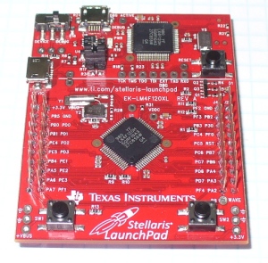
That’s a bucket of power, memory and I/O for not much money – you can get the LaunchPad board for around $15. This LaunchPad has the in-circuit debugger, two user buttons, an RGB LED and connectors for I/O and shield-like booster packs:

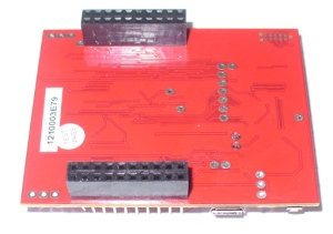
and the other side:

However the good news as far as we’re concerned is that you can now use it with the Energia Arduino-compatible IDE that we examined previously. Before rushing out to order your own Stellaris board, install Energia and examine the available functions and libraries to make sure you can run what you need. And if so, you’re set for some cheap Arduino power.

Installation

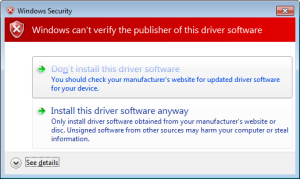
Installation is simple, just get your download from here. If you’re running Windows 7 – get the USB drivers from here. When you plug your LaunchPad into the USB for the first time, wait until after Windows attempts to install the drivers, then install drivers manually after download via Device manager … three times (JTAG, virtual serial port and DFU device). Use the debug USB socket (and set the switch to debug) when installing and uploading code. If you get the following warning from Windows, just click “Install this driver software anyway”:

Once the drivers are installed, plug in your LaunchPad, wait a moment – then run Energia. You can then select your board type and serial port just like the Arduino IDE. Then go ahead and upload the “blink” example…

Awesome – check out all that free memory space. In the same manner as the MSP430, there are some hardware<>sketch differences you need to be aware of. For example, how to refer to the I/O pins in Energia? A map has been provided for front:

… and back:

As you can imagine, the Stellaris MCUs are different to an AVR, so a lot of hardware-specific code doesn’t port over from the world of Arduino. One of the first things to remember is that the Stellaris is a 3.3V device. Code may or may not be interchangeable, so a little research will be needed to match up the I/O pins and rewrite the sketch accordingly. For example, instead of digital pins numbers, you use PX_Y – see the map above. So let’s say you want to run through the RGB LED… consider the following sketch:

int wait = 500;
void setup() 
{ 
 // initialize the digital pin as an output.
 pinMode(PF_1, OUTPUT); // red 
 pinMode(PF_3, OUTPUT); // green
 pinMode(PF_2, OUTPUT); // blue
}
void loop() 
{
 digitalWrite(PF_1, HIGH); 
 delay(wait); 
 digitalWrite(PF_1, LOW); 
 digitalWrite(PF_3, HIGH); 
 delay(wait); 
 digitalWrite(PF_3, LOW); 
 digitalWrite(PF_2, HIGH); 
 delay(wait); 
 digitalWrite(PF_2, LOW); 
}

Which simply blinks the red, green and blue LED elements in series. Using digital inputs is in the same vein, and again the buttons are wired so when pressed they go LOW. An example of this in the following sketch:

void setup() 
{ 
 // initialize the digital pins
 pinMode(PF_1, OUTPUT); // red 
 pinMode(PF_3, OUTPUT); // green
 pinMode(PF_2, OUTPUT); // blue

 pinMode(PF_4, INPUT_PULLUP); // left - note _PULLUP
 pinMode(PF_0, INPUT_PULLUP); // right - note _PULLUP 
}
void blinkfast() 
{
 for (int i=0; i<10; i++)
 {
 digitalWrite(PF_1, HIGH); 
 delay(250); 
 digitalWrite(PF_1, LOW); 
 digitalWrite(PF_3, HIGH); 
 delay(250); 
 digitalWrite(PF_3, LOW); 
 digitalWrite(PF_2, HIGH); 
 delay(250); 
 digitalWrite(PF_2, LOW); 
 }
}
void blinkslow() 
{
 for (int i=0; i<5; i++)
 {
 digitalWrite(PF_1, HIGH); 
 delay(1000); 
 digitalWrite(PF_1, LOW); 
 digitalWrite(PF_3, HIGH); 
 delay(1000); 
 digitalWrite(PF_3, LOW); 
 digitalWrite(PF_2, HIGH); 
 delay(1000); 
 digitalWrite(PF_2, LOW); 
 }
}
void loop()
{
 if (digitalRead(PF_4)==LOW) { blinkslow(); }
 if (digitalRead(PF_0)==LOW) { blinkfast(); }
}

And for the non-believers:

Where to from here? 

Sometimes you can be platform agnostic, and just pick something that does what you want with the minimum of time and budget. Or to put it another way, if you need a fast CPU and plenty of space but couldn’t be bothered don’t have time to work with Keil, Code Composer Studio, IAR etc – the Energia/Stellaris combination could solve your problem. There’s a growing Energia/Stellaris forum, and libraries can be found here. At the time of writing we found an I2C library as well.

However to take full advantage of the board, consider going back to the TI tools and move forward with them. You can go further with the tutorials and CCS etc from Texas Instruments own pages.

In the meanwhile have fun and keep checking into tronixstuff.com. Why not follow things on twitterGoogle+, subscribe  for email updates or RSS using the links on the right-hand column? And join our friendly Google Group – dedicated to the projects and related items on this website. Sign up – it’s free, helpful to each other –  and we can all learn something.

The post Exploring the TI Stellaris platform with Energia Arduino-compatible IDE appeared first on tronixstuff.