Posts with «data» label

Remote Water Quality Monitoring

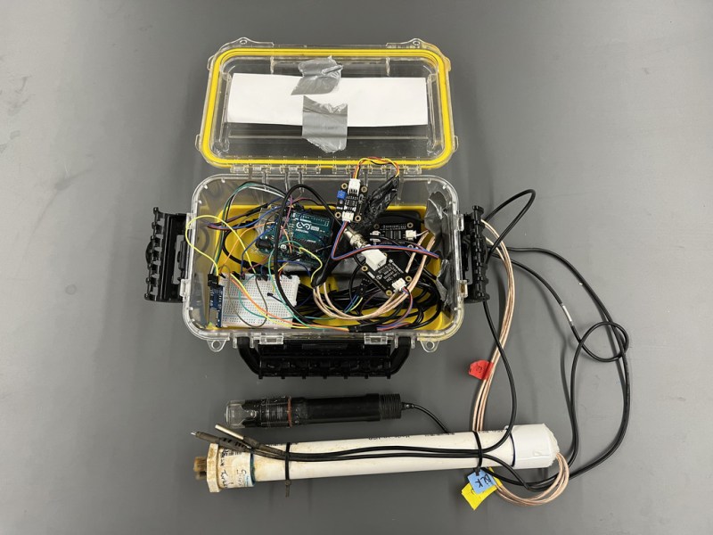
While it can be straightforward to distill water to high purity, this is rarely the best method for producing water for useful purposes. Even drinking water typically needs certain minerals in it, plants may need a certain pH, and wastewater systems have a whole host of other qualities that need to be measured. Measuring water quality is a surprisingly complex endeavor as a result and often involves a wide array of sensors, much like this water quality meter from [RowlesGroupResearch].

The water quality meters that they are putting to use are typically set up in remote locations, without power, and are targeting natural bodies of water and also wastewater treatment plants. Temperature and pH are simple enough to measure and grasp, but this device also includes sensors for total dissolved solids (TDS) and turbidity which are both methods for measuring various amounts and types of particles suspended in the water. The build is based around an Arduino so that it is easy for others to replicate, and is housed in a waterproof box with a large battery, and includes data logging to an SD card in order to make it easy to deploy in remote, outdoor settings and to gather the data at a later time.

The build log for this device also goes into detail about all of the steps needed to set this up from scratch, as well as a comprehensive bill of materials. This could be useful in plenty of professional settings such as community wastewater treatment facilities but also in situations where it’s believed that industrial activity may be impacting a natural body of water. For a water quality meter more focused on drinking water, though, we’d recommend this build that is trained on its own neural network.

Wearable Sensor Trained to Count Coughs

There are plenty of problems that are easy for humans to solve, but are almost impossibly difficult for computers. Even though it seems that with modern computing power being what it is we should be able to solve a lot of these problems, things like identifying objects in images remains fairly difficult. Similarly, identifying specific sounds within audio samples remains problematic, and as [Eivind] found, is holding up a lot of medical research to boot. To solve one specific problem he created a system for counting coughs of medical patients.

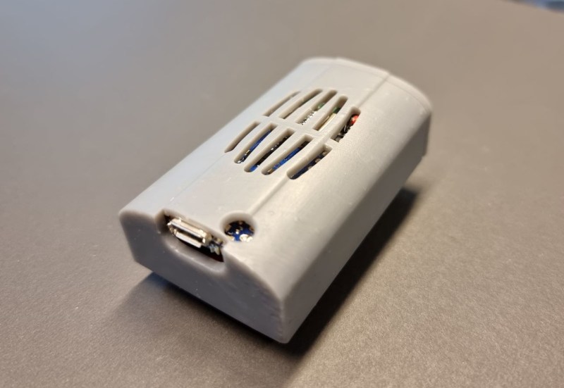
This was built with the idea of helping people with chronic obstructive pulmonary disease (COPD). Most of the existing methods for studying the disease and treating patients with it involves manually counting the number of coughs on an audio recording. While there are some software solutions to this problem to save some time, this device seeks to identify coughs in real time as they happen. It does this by training a model using tinyML to identify coughs and reject cough-like sounds. Everything runs on an Arduino Nano with BLE for communication.

While the only data the model has been trained on are sounds from [Eivind], the existing prototypes do seem to show promise. With more sound data this could be a powerful tool for patients with this disease. And, even though this uses machine learning on a small platform, we have seen before that Arudinos are plenty capable of being effective machine learning solutions with the right tools on board.

Hack a Day 16 Nov 00:00

GGWave Sings the Songs of Your Data

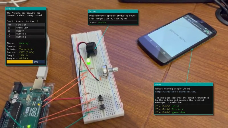
We’re suckers for alternative data transmission methods, and [Georgi Gerganov]’s ggwave made us smile. At its core, it’s doing what the phone modems of old used to do – sending data encoded as different audio tones. But GGwave does this with sophistication!

It splits the data into four-bit chunks, and uses 16 different frequency offsets to represent each possible value. But for each chunk, these offsets are added to one of six different base frequencies, which allows the receiving computer to tell which chunk it’s in. It’s like a simple framing concept, and it makes the resulting data sound charmingly like R2-D2. (It also uses begin and end markers to be double-sure of the framing.) The data is also sent with error correction, so small hiccups can get repaired automatically.

What really makes ggwave shine is that it’s ported to every platform you care about: ESP32, Arduino, Linux, Mac, Windows, Android, iOS, and anything that’ll run Python or JavaScript. So it’ll run in a browser. There’s even a GUI for playing around with alternative modulation schemes. Pshwew! This makes it easy for a minimalist microcontroller-based beeper button to control your desktop, or vice-versa. An ESP32 makes for an IoT-style WiFi-to-audio bridge. Write code on your cell phone, and you can broadcast it to any listening microcontroller. Whatever your use case, it’s probably covered.

Now the downside. The data rate is slow, around 64-160 bits per second, and the transmission is necessarily beepy-booopy, unless you pitch it up in to the ultrasound or use the radio-frequency HackRF demo. But maybe you want to hear when your devices are talking to each other? Or maybe you just think it’s cute? We do, but we wouldn’t want to have to transmit megabytes this way. But for a simple notification, a few bytes of data, a URL, or some configuration parameters, we can see this being a great software addition to any device that has a speaker and/or microphone.

Oh my god, check out this link from pre-history: a bootloader for the Arduino that runs on the line-in.

Hack a Day 06 Jul 19:30

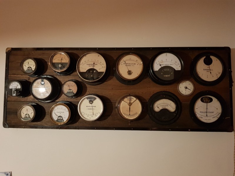
Supersized Weather Station Uses Antique Analog Meters

For most of us, getting weather information is as trivial as unlocking a smartphone or turning on a computer and pointing an app or browser at one’s weather site of choice. This is all well and good, but it lacks a certain panache that old weather stations had with their analog dials and stained wood cases. The weather station that [BuildComics] created marries both this antique aesthetic with modern weather data availability, and then dials it up a notch for this enormous analog weather station build.

The weather station uses 16 discrete dials, each modified with a different label for the specific type of data displayed. Some of them needed new glass, and others also needed coils to be modified to be driven with a lower current than they were designed as well, since each would be driven by one of two Arduinos in this project. Each are tied to a microcontroller output via a potentiometer which controls the needle’s position for the wildly different designs of meter. The microcontrollers themselves get weather information via the internet, which allows for about as up-to-date information about the weather as one could gather first-hand.

The amount of customization of these old meters is impressive, and what’s even more impressive is the project’s final weight. [BuildComics] reports that it took two people just to lift it onto the wall mount, which is not surprising given the amount of iron in some of these old analog meters. And, although not as common in the real world anymore, these old antique meters have plenty of repurposed uses beyond weather stations as well.

These Blobs Are Actually Clever Data Visualizations

I met John Kuiphoff a couple years ago and was blown away by some very clever data visualizations he shared based on people’s youtube channels. John’s back, and this time with another very creative approach to data visualization. In this project, John is wanting to display how much sunlight hits […]

Read more on MAKE

The post These Blobs Are Actually Clever Data Visualizations appeared first on Make: DIY Projects and Ideas for Makers.

Raiders of the Lost OS: Reclaiming A Piece of Polish IT History

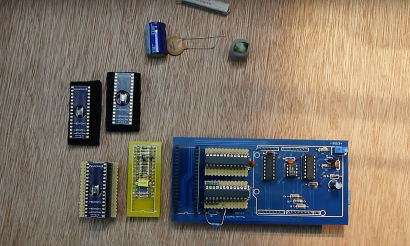
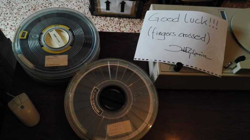
In today’s digital era, we almost take for granted that all our information is saved and backed up, be it on our local drives or in the cloud — whether automatically, manually, or via some other service.  For information from decades past, that isn’t always the case, and recovery can be a dicey process.  Despite the tricky challenges, the team at [Museo dell’Informatica Funzionante] and [mera400.pl], as well as researchers and scientists from various museums, institutions, and more all came together in the attempt to recover the Polish CROOK operating system believed to be stored on five magnetic tapes.

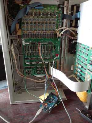
Originally stored at the Warsaw Museum of Technology, the tapes were ideally preserved, but — despite some preliminary test prep — the museum’s tape reader kept hanging at the 800 BPI NRZI encoded header, even though the rest of the tape was 1600 BPI phase encoding. Some head scratching later, the team decided to crack open their Qualstar 1052 tape reader and attempt to read the data directly off the circuits themselves!!

Using an Arduino Mega as a sampling device and the tape in test mode, the team were able to read the tapes, but the header remained inscrutable and accompanied by errors in the rest of the data. Promising nonetheless!

Switching gears, the decision was made to use a logic analyzer to read the tapes and use software to decode the data. While they waited for their new analyzer to ship, one of the team members, [Jacob Filipowicz] harnessed the power of Python to write a program called Nine Track Labs (pictured below) which would allow them to read any kind of magnetic tape, at any speed, BPI, and writing standard. Armed with the software and analyzer, the team was able to successfully recover the data from the tapes in its entirety without errors!

Among the data recovered, there were numerous versions of the CROOK operating system — allowing them to reproduce the OS’s development process, as well as hundreds of other files containing programs and tools hitherto believed to be lost. There was also a backup of a ‘live’ MERA-400 system with a binary CROOK-3 OS, ready to run in emulation. All things considered, the techno-archeological tour-de-force was a smashing success.

If — in your more modern travels — you need to recover an audio recording gone awry, know that you can retrieve that data with a hex editor.


Filed under: classic hacks, computer hacks

3 simple filtering techniques to eliminate noise

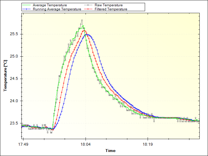
Increasing accuracy in the collection of data coming from sensors is a need that, sooner or later, Makers need to face. Paul Martinsen from MegunoLink created a tutorial to eliminate noise from sensor readings on Arduino with three simple filtering techniques.

The Averaging and Running Average techniques are easy to implement as they work by adding a number of measurements together, then dividing the total by the number of measurements. In both cases, the downside is that it can use a lot of memory.

The Exponential filter is a better solution for several reasons: it doesn’t require much memory, you can control how much filtering is applied with a single parameter, and it saves battery power because you don’t need to make many measurements at once. For this solution, they developed an Arduino filter library so you don’t need to go mad with math!

Interested? You can find the tutorial and explore the code on MegunoLing’s blog post here.

Arduino Blog 05 Sep 13:39

Get Arduino Data over the internet using jQuery and AJAX


Description


Have you ever wanted to transmit Arduino data over the internet?

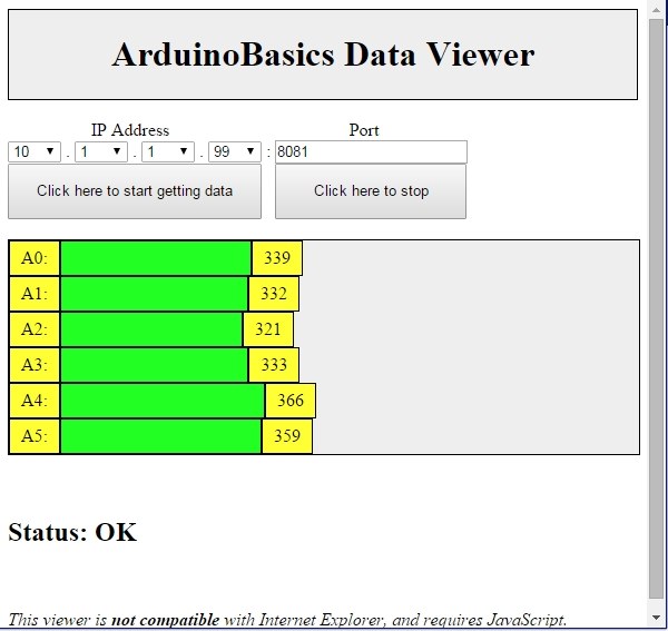
In this tutorial, we will design a web page that will retrieve Analog readings from the Arduino's Analog Pins and display them on a bar chart within the web page.

The web page will use jQuery and AJAX to request the data from the Arduino Web Server, allowing us to update the bar chart dynamically, without having to refresh the entire web page. The Arduino Web Server will send the Analog readings to the web page in JSON format where it will be processed and displayed accordingly.

In this tutorial, I will not have anything connected to the Arduino's Analog pins, which means the data retrieved will be that of randomly floating analog pins. Feel free to connect a potentiometer, temperature sensor or any other analog sensor to these pins if you want to create a more "useful" project.

The main aim here was to show you how to transmit the data in JSON format, and to update only a portion of the web page using asynchronous communication (using AJAX), to improve the performance of data retrieval and visualisation.


Parts Required:


Please note: The WIZnet ioShield-A ver1.1 actually comes with the WIZ550io board. So if you buy the ioShield-A, you will receive both boards. I have provided the link to the WIZ550io shield because you can buy that shield on its own. Regardless, you will need to use both boards for this tutorial.


Arduino Libraries and IDE


To program the Arduino you will need to download the Arduino IDE, and install the WIZnet Ethernet Library. The Arduino IDE version used in this tutorial was version 1.6.4.
You may want to read the WIZnet wiki information for each WIZnet shield before use.


ARDUINO CODE:


Full description of the Arduino code is included in the YouTube video above. Once you have set up your Arduino Web Server, you should be able to ping it. Look at this website, if you don't know how to use the windows ping feature.


Getting the Arduino Board onto the internet:


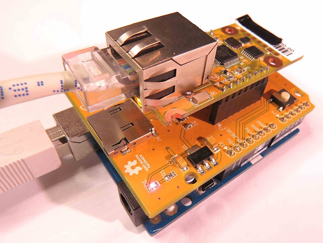
There isn't anything really to hook up for this project. You just have to align the pins for each board and stack them. You can power the Arduino via the USB cable. This will also be useful for debugging and printing to the Serial monitor. An ethernet cable needs to connect the WIZ550io board's ethernet port to your internet/network router

  • The WIZ550io board goes on the top

  • The ioShield-A is in the middle

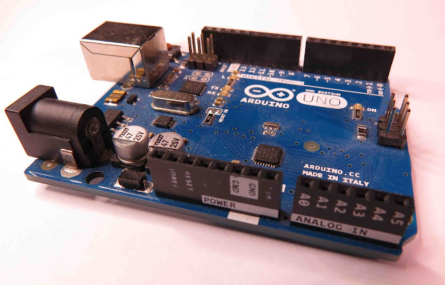
  • The Arduino UNO is on the bottom

  • This is what it looks like when they are stacked together

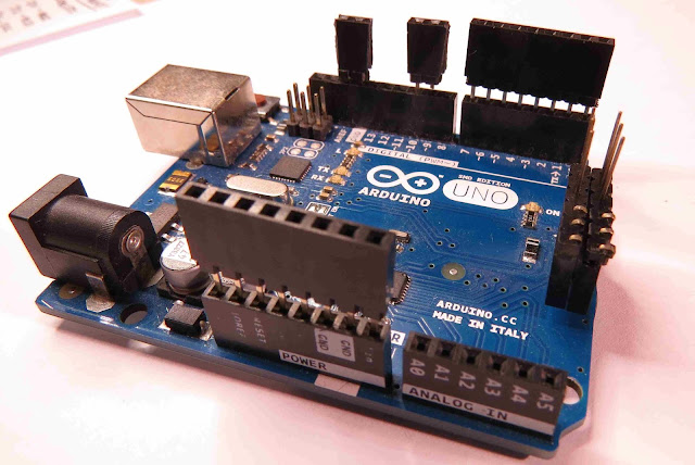
  • If you want to gain easy access to the Analog or digital pins without de-soldering the ioShield-A, you can introduce some female headers like this:

  • Please note that the ioShield-A utilises a number of pins on the Arduino UNO - including: D2, D4, D7, D10, GND, and IOREF, RESET, 5V, GND, GND and ICSP pins
  • All Analog pins are available for use


Set the Arduino Web Server on your local network


You can test this project on your local network. You just have to choose an available IP address and PORT within your router's IP range. If you don't know your local IP address range - you can have a look at this site to give you a helping hand.


Set the Arduino Web Server to be accessed from anywhere in the world


If you want to access your Arduino from anywhere in the world, you need to set up Port Forwarding on your internet network router. The following useful guides will hopefully get you on the right track, if you have never set up Port forwarding.


In my case, I programmed the Arduino UNO Web Server to take the following ip address on my internal network: 10.1.1.99

I programmed the Arduino Web Server to listen for Web Browsers on port 8081.
So if I wanted to connect to the Arduino Web Server through my home network, I just had to type in this web address into my web browser: http://10.1.1.99:8081

If you plan to connect to the Arduino using port 80 (which is the default port for web browsers), you can just type the IP address without specifying the port (eg. http://10.1.1.99/ )

The web browser should display the Arduino data in JSON format (the YouTube video above will show you what that looks like).

Once I knew I could connect to the Arduino in my internal network, I then set up port forwarding on my router so that I could type in my external IP address and special port to tunnel my way into my Arduino Web Server on my internal network. This is what I had to do on my router, but you may need to do something different.

  1. My first step was to find out my public/external IP address by typing "what is my IP address" into google. If you want to know your external IP address click here.
  2. I then typed my router's ip address into a web browser, and logged into my router.
  3. I went to the advanced settings tab
  4. Selected "Port Forwarding" from the side menu
  5. Filled out all of the details on the first line of the Ports list
    • Enable box = ticked
    • Description = Arduino
    • WAN interface = pppoe_atm0/ppp0
    • Inbound port = 8082
    • Type = TCP
    • Private IP address = 10.1.1.99
    • Private port = 8081
  6. Saved the settings

Now that I had port forwarding enabled, I could type the ip address (that I obtained in step 1) into my browser and specified port 8082 (instead of 8081) - eg. http://190.11.70.253:8082/

And now I can access my Arduino Web server from anywhere in the world. I can even access it from my smart phone. Once again, this will only return the Analog data in JSON format.


The Web Page GUI


The Arduino is now on the internet, so there are two options. You can either


Instructions on how to use these web pages, are listed below the HTML code.


To retrieve data from your Arduino Web Server, please make sure that it is connected and visible from outside of you local network. You will need to have port forwarding enabled. Information on port forwarding is described above.
  1. Find what your external IP address is.
  2. Enter this address using the IP address drop-down boxes within the "ArduinoBasics Webserver Data viewer" web page
  3. Enter the port forwarding port number (eg. 8082) into the box labelled "Port"
  4. Then click on the "Click here to start getting data" button - you should start to see the bar charts moving and status should be OK
  5. If the bar charts do not move, and the status message says "Failed to get DATA!!" - then the web page was unable to connect to the Arduino for some reason.


Troubleshooting

  • You may want to type in the web address into your web browser, to make sure that data is being retrieved.
  • You can also open the Serial monitor in the Arduino IDE to make sure that an IP address is being displayed
  • Ensure that you have enabled the port forwarding option on your router
  • Have a look at Developer Tools within Google Chrome to help diagnose web page related issues.
  • The web page will not work properly if you use Internet Explorer or if you have javascript disabled within your browser.


Concluding comments


This tutorial showed you how to connect to your Arduino UNO over the internet, and retrieve data in JSON format using jQuery and AJAX. The web page can be modified to suit your own needs, plus it would be more useful if the Arduino was actually monitoring something, rather than logging data from floating pins. It would also be useful if the Arduino could be controlled to blink an LED, or to turn a motor... but I will leave that project for another day. Thank you.

If you like this page, please do me a favour and show your appreciation :

 
Visit my ArduinoBasics Google + page.
Follow me on Twitter by looking for ScottC @ArduinoBasics.
I can also be found on Pinterest and Instagram.
Have a look at my videos on my YouTube channel.
             
This project would not have been possible without WIZnet's collaborative effort.
Please visit their site for more cool Ethernet products.


However, if you do not have a google profile...
Feel free to share this page with your friends in any way you see fit.

Get Arduino Data over the internet using jQuery and AJAX

Description

Have you ever wanted to transmit Arduino data over the internet?

In this tutorial, we will design a web page that will retrieve Analog readings from the Arduino's Analog Pins and display them on a bar chart within the web page.

The web page will use jQuery and AJAX to request the data from the Arduino Web Server, allowing us to update the bar chart dynamically, without having to refresh the entire web page. The Arduino Web Server will send the Analog readings to the web page in JSON format where it will be processed and displayed accordingly.

In this tutorial, I will not have anything connected to the Arduino's Analog pins, which means the data retrieved will be that of randomly floating analog pins. Feel free to connect a potentiometer, temperature sensor or any other analog sensor to these pins if you want to create a more "useful" project.

The main aim here was to show you how to transmit the data in JSON format, and to update only a portion of the web page using asynchronous communication (using AJAX), to improve the performance of data retrieval and visualisation.


Arduino Libraries and IDE

To program the Arduino you will need to download the Arduino IDE, and install the WIZnet Ethernet Library. The Arduino IDE version used in this tutorial was version 1.6.4.
You may want to read the WIZnet wiki information for each WIZnet shield before use.


ARDUINO CODE:

Full description of the Arduino code is included in the YouTube video above. Once you have set up your Arduino Web Server, you should be able to ping it. Look at this website, if you don't know how to use the windows ping feature.


Getting the Arduino Board onto the internet:

There isn't anything really to hook up for this project. You just have to align the pins for each board and stack them. You can power the Arduino via the USB cable. This will also be useful for debugging and printing to the Serial monitor. An ethernet cable needs to connect the WIZ550io board's ethernet port to your internet/network router

  • The WIZ550io board goes on the top

  • The ioShield-A is in the middle

  • The Arduino UNO is on the bottom

  • This is what it looks like when they are stacked together

  • If you want to gain easy access to the Analog or digital pins without de-soldering the ioShield-A, you can introduce some female headers like this:

  • Please note that the ioShield-A utilises a number of pins on the Arduino UNO - including: D2, D4, D7, D10, GND, and IOREF, RESET, 5V, GND, GND and ICSP pins
  • All Analog pins are available for use


Set the Arduino Web Server on your local network

You can test this project on your local network. You just have to choose an available IP address and PORT within your router's IP range. If you don't know your local IP address range - you can have a look at this site to give you a helping hand.


Set the Arduino Web Server to be accessed from anywhere in the world

If you want to access your Arduino from anywhere in the world, you need to set up Port Forwarding on your internet network router. The following useful guides will hopefully get you on the right track, if you have never set up Port forwarding.


In my case, I programmed the Arduino UNO Web Server to take the following ip address on my internal network: 10.1.1.99

I programmed the Arduino Web Server to listen for Web Browsers on port 8081.
So if I wanted to connect to the Arduino Web Server through my home network, I just had to type in this web address into my web browser: http://10.1.1.99:8081

If you plan to connect to the Arduino using port 80 (which is the default port for web browsers), you can just type the IP address without specifying the port (eg. http://10.1.1.99/ )

The web browser should display the Arduino data in JSON format (the YouTube video above will show you what that looks like).

Once I knew I could connect to the Arduino in my internal network, I then set up port forwarding on my router so that I could type in my external IP address and special port to tunnel my way into my Arduino Web Server on my internal network. This is what I had to do on my router, but you may need to do something different.

  1. My first step was to find out my public/external IP address by typing "what is my IP address" into google. If you want to know your external IP address click here.
  2. I then typed my router's ip address into a web browser, and logged into my router.
  3. I went to the advanced settings tab
  4. Selected "Port Forwarding" from the side menu
  5. Filled out all of the details on the first line of the Ports list
    • Enable box = ticked
    • Description = Arduino
    • WAN interface = pppoe_atm0/ppp0
    • Inbound port = 8082
    • Type = TCP
    • Private IP address = 10.1.1.99
    • Private port = 8081
  6. Saved the settings

Now that I had port forwarding enabled, I could type the ip address (that I obtained in step 1) into my browser and specified port 8082 (instead of 8081) - eg. http://190.11.70.253:8082/

And now I can access my Arduino Web server from anywhere in the world. I can even access it from my smart phone. Once again, this will only return the Analog data in JSON format.


The Web Page GUI

The Arduino is now on the internet, so there are two options. You can either

Instructions on how to use these web pages, are listed below the HTML code.


To retrieve data from your Arduino Web Server, please make sure that it is connected and visible from outside of you local network. You will need to have port forwarding enabled. Information on port forwarding is described above.

  1. Find what your external IP address is.
  2. Enter this address using the IP address drop-down boxes within the "ArduinoBasics Webserver Data viewer" web page
  3. Enter the port forwarding port number (eg. 8082) into the box labelled "Port"
  4. Then click on the "Click here to start getting data" button - you should start to see the bar charts moving and status should be OK
  5. If the bar charts do not move, and the status message says "Failed to get DATA!!" - then the web page was unable to connect to the Arduino for some reason.


Troubleshooting

  • You may want to type in the web address into your web browser, to make sure that data is being retrieved.
  • You can also open the Serial monitor in the Arduino IDE to make sure that an IP address is being displayed
  • Ensure that you have enabled the port forwarding option on your router
  • Have a look at Developer Tools within Google Chrome to help diagnose web page related issues.
  • The web page will not work properly if you use Internet Explorer or if you have javascript disabled within your browser.

Concluding comments

This tutorial showed you how to connect to your Arduino UNO over the internet, and retrieve data in JSON format using jQuery and AJAX. The web page can be modified to suit your own needs, plus it would be more useful if the Arduino was actually monitoring something, rather than logging data from floating pins. It would also be useful if the Arduino could be controlled to blink an LED, or to turn a motor... but I will leave that project for another day. I hope you enjoyed this tutorial - if it helped you in any way, please consider donating a small "tip" into my money jar. Thank you.


If you like this page, please do me a favour and show your appreciation :

 
Visit my ArduinoBasics Google + page.
Follow me on Twitter by looking for ScottC @ArduinoBasics.
I can also be found on Pinterest and Instagram.
Have a look at my videos on my YouTube channel.


This project would not have been possible without WIZnet's collaborative effort.
Please visit their site for more cool Ethernet products.


However, if you do not have a google profile...
Feel free to share this page with your friends in any way you see fit.

CH376S USB Read/Write module

Have you ever wondered if there was a way to store and retrieve data from a USB stick with an Arduino UNO? Most people choose SD cards to store their project data, but you may be surprised there IS a way!
IC Station have a nice little module which allows you store and retrieve your Arduino (or other MCU) project data to a USB stick.
 
I am not too sure why USB storage is not widely used in Arduino projects? These modules are not expensive, they have been around for quite a while, and are relatively simple to use. You do not need any libraries to get them to work, however, I must say that documentation for this module is not that easy to find. This site and this document proved to be very useful in my endevour to get this module working, and I hope my tutorial below will help you get started and bridge some of the information gaps.
 
The "CH376S USB read/write module" has a CH376S chip onboard which does most of the hard work for you. All you have to do is send the module some commands from the Arduino and the CH376S chip will do the rest. You can communicate with the module in three different ways:

  • Parallel communication
  • SPI communication
  • and Serial (UART) communication.

This project will show you the connections and code for the Serial (UART) communication method only.


Parts Required:

Remove the Jumper

When the CH376S USB module arrives in it's package, it will have a jumper between the TXD pin and GND. You will need to remove this jumper to make the necessary connections between the Arduino UNO and the CH376S USB module.


Fritzing Sketch

Please note, that the Arduino Sketch makes use of the Arduino UNO's onboard LED on digital pin 13. The Fritzing sketch below shows an LED + 300 ohm resistor on a breadboard. This is optional. The LED is not a necessary component of CH376S module communication.

Also be aware that the CH376S USB module has an onboard LED just above the TXD and GND pins near the USB port. This LED will only turn on providing the CH376S module is in USB mode AND a USB device has been inserted into the USB port. Both conditions must be met before the module's onboard LED will illuminate. You will not see the LED turn on just by powering the board.
 
The wire diagram below is the correct setup for Serial communication between an Arduino UNO and the CH376S module. If you wish to use SPI or Parallel communication, you will need to refer to the datasheet.


Arduino Sketch


  1
2
3
4
5
6
7
8
9
10
11
12
13
14
15
16
17
18
19
20
21
22
23
24
25
26
27
28
29
30
31
32
33
34
35
36
37
38
39
40
41
42
43
44
45
46
47
48
49
50
51
52
53
54
55
56
57
58
59
60
61
62
63
64
65
66
67
68
69
70
71
72
73
74
75
76
77
78
79
80
81
82
83
84
85
86
87
88
89
90
91
92
93
94
95
96
97
98
99
100
101
102
103
104
105
106
107
108
109
110
111
112
113
114
115
116
117
118
119
120
121
122
123
124
125
126
127
128
129
130
131
132
133
134
135
136
137
138
139
140
141
142
143
144
145
146
147
148
149
150
151
152
153
154
155
156
157
158
159
160
161
162
163
164
165
166
167
168
169
170
171
172
173
174
175
176
177
178
179
180
181
182
183
184
185
186
187
188
189
190
191
192
193
194
195
196
197
198
199
200
201
202
203
204
205
206
207
208
209
210
211
212
213
214
215
216
217
218
219
220
221
222
223
224
225
226
227
228
229
230
231
232
233
234
235
236
237
238
239
240
241
242
243
244
245
246
247
248
249
250
251
252
253
254
255
256
257
258
259
260
261
262
263
264
265
266
267
268
269
270
271
272
273
274
275
276
277
278
279
280
281
282
283
284
285
286
287
288
289
290
291
292
293
294
295
296
297
298
299
300
301
302
303
304
305
306
307
308
309
310
311
312
313
314
315
316
317
318
319
320
321
322
323
324
325
326
327
328
329
330
331
332
333
334
335
336
337
338
339
340
341
342
343
344
345
346
347
348
349
350
351
352
353
354
355
356
357
358
359
360
361
362
363
364
365
366
367
368
369
370
371
372
373
374
375
376
377
378
379
380
381
382
383
384
385
386
387
388
389
390
391
392
393
394
395
396
397
398
399
400
401
402
403
404
405
406
407
408
409
410
411
412
413
414
415
416
417
418
419
420
421
422
423
424
425
426
427
428
429
430
431
432
433
434
435
436
437
438
439
440
441
442
443
444
445
446
447
448
449
450
451
452
453
454
455
456
457
458
459
460
461
462
463
464
465
466
467
468
469
470
471
472
473
474
475
476
477
478
479
480
481
482
483
484
485
486
487
488
489
490
491
492
493
494
495
496
497
498
499
500
501
502
503
504
505

/* ===============================================================
      Project: CH376S USB Read/Write Module testing ground
       Author: Scott C
      Created: 1st May 2015
  Arduino IDE: 1.6.2
      Website: http://arduinobasics.blogspot.com/p/arduino-basics-projects-page.html
  Description: This project will allow you to perform many of the functions available on the CH376S module.
               Checking connection to the module, putting the module into USB mode, resetting the module, 
               reading, writing, appending text to files on the USB stick. This is very useful alternative to
               SD card modules, plus it doesn't need any libraries.
================================================================== */

#include <SoftwareSerial.h>

byte computerByte; //used to store data coming from the computer
byte USB_Byte; //used to store data coming from the USB stick
int LED = 13; //the LED is connected to digital pin 13
int timeOut = 2000; //TimeOut is 2 seconds. This is the amount of time you wish to wait for a response from the CH376S module.
String wrData = "What is the meaning of life ?"; //We will write this data to a newly created file.
String wrData2 = "42"; //We will append this data to an already existing file.

SoftwareSerial USB(10, 11); // Digital pin 10 on Arduino (RX) connects to TXD on the CH376S module
                                                      // Digital pin 11 on Arduino (TX) connects to RXD on the CH376S module
                                                      // GND on Arduino to GND on CH376S module
                                                      // 5V on Arduino to 5V on CH376S module
//==============================================================================================================================================
void setup() {
  Serial.begin(9600); // Setup serial communication with the computer (using a baud rate of 9600 on serial monitor)
  USB.begin(9600); // Setup serial communication with the CH376S module (using the default baud rate of 9600)
  pinMode(LED,OUTPUT); // Define digital pin 13 as an OUTPUT pin - so that we can use it with an LED
  digitalWrite(LED,LOW); // Turn off the LED
}

//================================================================================================================================================
void loop() {
  if(Serial.available()){
    computerByte = Serial.read(); //read any incoming bytes from the Serial monitor, and store this byte in the variable called computerByte
    if(computerByte==49){ //1 //If you send the number 1 from the serial monitor, the arduino will read it as digital number 49. Google "ascii table" for more info.
      printCommandHeader("COMMAND1: CHECK CONNECTION");
      checkConnection(0x01);                           // Check for successful connection and communication with the CH376S module.
    } 
    if(computerByte==50){ //2
     printCommandHeader("COMMAND2: set_USB_Mode");
      set_USB_Mode(0x06);                              // Code used to enable read/write communication and monitoring of the USB stick
    }
    if(computerByte==51){ //3
      printCommandHeader("COMMAND3: resetALL");
      resetALL();                                      // Reset the USB device
    }
    if(computerByte==52){ //4
      printCommandHeader("COMMAND4: Create and Write to File : TEST4.TXT");
      writeFile("TEST4.TXT", wrData); // Create a file called TEST4.TXT and then Write the contents of wrData to this file
    }
    if(computerByte==53){ //5
      printCommandHeader("COMMAND5: Read File: TEST4.TXT");
      readFile("TEST4.TXT"); // Read the contents of this file on the USB disk, and display contents in the Serial Monitor
    }
    if(computerByte==54){ //6
      printCommandHeader("COMMAND6: Append data to file: TEST4.TXT");
      appendFile("TEST4.TXT", wrData2); // Append data to the end of the file.
    }
    if(computerByte==55){ //7
      printCommandHeader("COMMAND7: Delete File: TEST4.TXT");
      fileDelete("TEST4.TXT"); // Delete the file named TEST4.TXT
    }
    if(computerByte==56){ //8
      printCommandHeader("COMMAND8: Read File: TEST2.TXT");
      readFile("TEST2.TXT"); // Read the contents of the TEST2.TXT file on the USB disk, and display contents in the Serial Monitor
    }
    if(computerByte==57){ //9
      printCommandHeader("COMMAND9: Read File: TEST3.TXT");
      readFile("TEST3.TXT"); // Read the contents of the TEST3.TXT file on the USB disk, and display contents in the Serial Monitor
    }
  }
  
  if(USB.available()){ // This is here to capture any unexpected data transmitted by the CH376S module
    Serial.print("CH376S has just sent this code:");
    Serial.println(USB.read(), HEX);
  }
}

//END OF LOOP FUNCTION ========================================================================================================================================

//print Command header
void printCommandHeader(String header){
   Serial.println("======================");
   Serial.println("");
   Serial.println(header);
   Serial.println("----------------------");
}

//checkConnection==================================================================================
//This function is used to check for successful communication with the CH376S module. This is not dependant of the presence of a USB stick.
//Send any value between 0 to 255, and the CH376S module will return a number = 255 - value. 
void checkConnection(byte value){
  USB.write(0x57);
  USB.write(0xAB);
  USB.write(0x06);
  USB.write(value);
  
  if(waitForResponse("checking connection")){ //wait for a response from the CH376S. If CH376S responds, it will be true. If it times out, it will be false.
    if(getResponseFromUSB()==(255-value)){
       Serial.println(">Connection to CH376S was successful.");
       blinkLED();                               //blink the LED for 1 second if the connection was successful
    } else {
      Serial.print(">Connection to CH376S - FAILED.");
    }
  }
}

//set_USB_Mode=====================================================================================
//Make sure that the USB is inserted when using 0x06 as the value in this specific code sequence
void set_USB_Mode (byte value){
  USB.write(0x57);
  USB.write(0xAB);
  USB.write(0x15);
  USB.write(value);
  
  delay(20);
  
  if(USB.available()){
    USB_Byte=USB.read();
    //Check to see if the command has been successfully transmitted and acknowledged.
    if(USB_Byte==0x51){ // If true - the CH376S has acknowledged the command.
        Serial.println("set_USB_Mode command acknowledged"); //The CH376S will now check and monitor the USB port
        USB_Byte = USB.read();
        
        //Check to see if the USB stick is connected or not.
        if(USB_Byte==0x15){ // If true - there is a USB stick connected
          Serial.println("USB is present");
          blinkLED();                                     // If the process was successful, then turn the LED on for 1 second
        } else {
          Serial.print("USB Not present. Error code:"); // If the USB is not connected - it should return an Error code = FFH
          Serial.print(USB_Byte, HEX);
          Serial.println("H");
        }
        
    } else {
        Serial.print("CH3765 error! Error code:");
        Serial.print(USB_Byte, HEX);
        Serial.println("H");
    }   
  }
  delay(20);
}

//resetALL=========================================================================================
//This will perform a hardware reset of the CH376S module - which usually takes about 35 msecs =====
void resetALL(){
    USB.write(0x57);
    USB.write(0xAB);
    USB.write(0x05);
    Serial.println("The CH376S module has been reset !");
    delay(200);
}

//readFile=====================================================================================
//This will send a series of commands to read data from a specific file (defined by fileName)
void readFile(String fileName){
  resetALL();                     //Reset the module
  set_USB_Mode(0x06);             //Set to USB Mode
  diskConnectionStatus();         //Check that communication with the USB device is possible
  USBdiskMount();                 //Prepare the USB for reading/writing - you need to mount the USB disk for proper read/write operations.
  setFileName(fileName);          //Set File name
  fileOpen();                     //Open the file for reading
  int fs = getFileSize(); //Get the size of the file
  fileRead();                     //***** Send the command to read the file ***
  fileClose(0x00);                //Close the file
}

//writeFile========================================================================================
//is used to create a new file and then write data to that file. "fileName" is a variable used to hold the name of the file (e.g TEST.TXT). "data" should not be greater than 255 bytes long. 
void writeFile(String fileName, String data){
  resetALL();                     //Reset the module
  set_USB_Mode(0x06);             //Set to USB Mode
  diskConnectionStatus();         //Check that communication with the USB device is possible
  USBdiskMount();                 //Prepare the USB for reading/writing - you need to mount the USB disk for proper read/write operations.
  setFileName(fileName);          //Set File name
  if(fileCreate()){ //Try to create a new file. If file creation is successful
    fileWrite(data);              //write data to the file.
  } else {
    Serial.println("File could not be created, or it already exists");
  }
  fileClose(0x01);
}

//appendFile()====================================================================================
//is used to write data to the end of the file, without erasing the contents of the file.
void appendFile(String fileName, String data){
    resetALL();                     //Reset the module
    set_USB_Mode(0x06);             //Set to USB Mode
    diskConnectionStatus();         //Check that communication with the USB device is possible
    USBdiskMount();                 //Prepare the USB for reading/writing - you need to mount the USB disk for proper read/write operations.
    setFileName(fileName);          //Set File name
    fileOpen();                     //Open the file
    filePointer(false); //filePointer(false) is to set the pointer at the end of the file. filePointer(true) will set the pointer to the beginning.
    fileWrite(data);                //Write data to the end of the file
    fileClose(0x01);                //Close the file using 0x01 - which means to update the size of the file on close.
}
  
//setFileName======================================================================================
//This sets the name of the file to work with
void setFileName(String fileName){
  Serial.print("Setting filename to:");
  Serial.println(fileName);
  USB.write(0x57);
  USB.write(0xAB);
  USB.write(0x2F);
  USB.write(0x2F); // Every filename must have this byte to indicate the start of the file name.
  USB.print(fileName); // "fileName" is a variable that holds the name of the file. eg. TEST.TXT
  USB.write((byte)0x00); // you need to cast as a byte - otherwise it will not compile. The null byte indicates the end of the file name.
  delay(20);
}

//diskConnectionStatus================================================================================
//Check the disk connection status
void diskConnectionStatus(){
  Serial.println("Checking USB disk connection status");
  USB.write(0x57);
  USB.write(0xAB);
  USB.write(0x30);

  if(waitForResponse("Connecting to USB disk")){ //wait for a response from the CH376S. If CH376S responds, it will be true. If it times out, it will be false.
    if(getResponseFromUSB()==0x14){ //CH376S will send 0x14 if this command was successful
       Serial.println(">Connection to USB OK");
    } else {
      Serial.print(">Connection to USB - FAILED.");
    }
  }
}

//USBdiskMount========================================================================================
//initialise the USB disk and check that it is ready - this process is required if you want to find the manufacturing information of the USB disk
void USBdiskMount(){
  Serial.println("Mounting USB disk");
  USB.write(0x57);
  USB.write(0xAB);
  USB.write(0x31);

  if(waitForResponse("mounting USB disk")){ //wait for a response from the CH376S. If CH376S responds, it will be true. If it times out, it will be false.
    if(getResponseFromUSB()==0x14){ //CH376S will send 0x14 if this command was successful
       Serial.println(">USB Mounted - OK");
    } else {
      Serial.print(">Failed to Mount USB disk.");
    }
  }
}

//fileOpen========================================================================================
//opens the file for reading or writing
void fileOpen(){
  Serial.println("Opening file.");
  USB.write(0x57);
  USB.write(0xAB);
  USB.write(0x32);
  if(waitForResponse("file Open")){ //wait for a response from the CH376S. If CH376S responds, it will be true. If it times out, it will be false.
    if(getResponseFromUSB()==0x14){ //CH376S will send 0x14 if this command was successful
       Serial.println(">File opened successfully.");
    } else {
      Serial.print(">Failed to open file.");
    }
  }
}

//setByteRead=====================================================================================
//This function is required if you want to read data from the file. 
boolean setByteRead(byte numBytes){
  boolean bytesToRead=false;
  int timeCounter = 0;
  USB.write(0x57);
  USB.write(0xAB);
  USB.write(0x3A);
  USB.write((byte)numBytes); //tells the CH376S how many bytes to read at a time
  USB.write((byte)0x00);
  if(waitForResponse("setByteRead")){ //wait for a response from the CH376S. If CH376S responds, it will be true. If it times out, it will be false.
    if(getResponseFromUSB()==0x1D){ //read the CH376S message. If equal to 0x1D, data is present, so return true. Will return 0x14 if no data is present.
      bytesToRead=true;
    }
  }
  return(bytesToRead);


//getFileSize()===================================================================================
//writes the file size to the serial Monitor.
int getFileSize(){
  int fileSize=0;
  Serial.println("Getting File Size");
  USB.write(0x57);
  USB.write(0xAB);
  USB.write(0x0C);
  USB.write(0x68);
  delay(100);
  Serial.print("FileSize =");
  if(USB.available()){
    fileSize = fileSize + USB.read();
  } 
  if(USB.available()){
    fileSize = fileSize + (USB.read()*255);
  } 
  if(USB.available()){
    fileSize = fileSize + (USB.read()*255*255);
  } 
  if(USB.available()){
    fileSize = fileSize + (USB.read()*255*255*255);
  }     
  Serial.println(fileSize);
  delay(10);
  return(fileSize);
}


//fileRead========================================================================================
//read the contents of the file
void fileRead(){
  Serial.println("Reading file:");
  byte firstByte = 0x00; //Variable to hold the firstByte from every transmission. Can be used as a checkSum if required.
  byte numBytes = 0x40; //The maximum value is 0x40 = 64 bytes
 
  while(setByteRead(numBytes)){ //This tells the CH376S module how many bytes to read on the next reading step. In this example, we will read 0x10 bytes at a time. Returns true if there are bytes to read, false if there are no more bytes to read.
    USB.write(0x57);
    USB.write(0xAB);
    USB.write(0x27); //Command to read ALL of the bytes (allocated by setByteRead(x))
    if(waitForResponse("reading data")){ //Wait for the CH376S module to return data. TimeOut will return false. If data is being transmitted, it will return true.
        firstByte=USB.read(); //Read the first byte
        while(USB.available()){
          Serial.write(USB.read()); //Send the data from the USB disk to the Serial monitor
          delay(1); //This delay is necessary for successful Serial transmission
        }
    }
    if<!continueRead()){><span>//prepares the module for further reading. If false, stop reading.</span><br />      <span>break</span>; <span>//You need the continueRead() method if the data to be read from the USB device is greater than numBytes.</span><br />    }<br />  }<br />  <span><b>Serial</b></span>.<span>println</span>();<br />  <span><b>Serial</b></span>.<span>println</span>(<span>"NO MORE DATA"</span>);<br />}<br /><br /><span>//fileWrite=======================================================================================</span><br /><span>//are the commands used to write to the file</span><br /><span>void</span> fileWrite(<span>String</span> data){<br />  <span><b>Serial</b></span>.<span>println</span>(<span>"Writing to file:"</span>);<br />  <span>byte</span> dataLength = (<span>byte</span>) data.<span>length</span>(); <span>// This variable holds the length of the data to be written (in bytes)</span><br />  <span><b>Serial</b></span>.<span>println</span>(data);<br />  <span><b>Serial</b></span>.<span>print</span>(<span>"Data Length:"</span>);<br />  <span><b>Serial</b></span>.<span>println</span>(dataLength);<br />  <span>delay</span>(100);<br />  <span>// This set of commands tells the CH376S module how many bytes to expect from the Arduino. (defined by the "dataLength" variable)</span><br />  USB.<span>write</span>(0x57);<br />  USB.<span>write</span>(0xAB);<br />  USB.<span>write</span>(0x3C);<br />  USB.<span>write</span>((<span>byte</span>) dataLength);<br />  USB.<span>write</span>((<span>byte</span>) 0x00);<br />  <span>if</span>(waitForResponse(<span>"setting data Length"</span>)){ <span>// Wait for an acknowledgement from the CH376S module before trying to send data to it</span><br />    <span>if</span>(getResponseFromUSB()==0x1E){ <span>// 0x1E indicates that the USB device is in write mode.</span><br />      USB.<span>write</span>(0x57);<br />      USB.<span>write</span>(0xAB);<br />      USB.<span>write</span>(0x2D);<br />      USB.<span>print</span>(data); <span>// write the data to the file</span><br />  <br />      <span>if</span>(waitForResponse(<span>"writing data to file"</span>)){ <span>// wait for an acknowledgement from the CH376S module</span><br />      }<br />      <span><b>Serial</b></span>.<span>print</span>(<span>"Write code (normally FF and 14): "</span>);<br />      <span><b>Serial</b></span>.<span>print</span>(USB.<span>read</span>(),<span>HEX</span>); <span>// code is normally 0xFF</span><br />      <span><b>Serial</b></span>.<span>print</span>(<span>","</span>);<br />      USB.<span>write</span>(0x57);<br />      USB.<span>write</span>(0xAB);<br />      USB.<span>write</span>(0x3D); <span>// This is used to update the file size. Not sure if this is necessary for successful writing.</span><br />      <span>if</span>(waitForResponse(<span>"updating file size"</span>)){ <span>// wait for an acknowledgement from the CH376S module</span><br />      }<br />      <span><b>Serial</b></span>.<span>println</span>(USB.<span>read</span>(),<span>HEX</span>); <span>//code is normally 0x14</span><br />    }<br />  }<br />}<br /><br /><span>//continueRead()==================================================================================</span><br /><span>//continue to read the file : I could not get this function to work as intended.</span><br /><span>boolean</span> continueRead(){<br />  <span>boolean</span> readAgain = <span>false</span>;<br />  USB.<span>write</span>(0x57);<br />  USB.<span>write</span>(0xAB);<br />  USB.<span>write</span>(0x3B);<br />  <span>if</span>(waitForResponse(<span>"continueRead"</span>)){ <span>//wait for a response from the CH376S. If CH376S responds, it will be true. If it times out, it will be false.</span><br />     <span>if</span>(getResponseFromUSB()==0x14){ <span>//CH376S will send 0x14 if this command was successful</span><br />       readAgain=<span>true</span>;<br />     }<br />  }<br />  <span>return</span>(readAgain);<br />} <br /><br /><span>//fileCreate()========================================================================================</span><br /><span>//the command sequence to create a file</span><br /><span>boolean</span> fileCreate(){<br />  <span>boolean</span> createdFile = <span>false</span>;<br />  USB.<span>write</span>(0x57);<br />  USB.<span>write</span>(0xAB);<br />  USB.<span>write</span>(0x34);<br />  <span>if</span>(waitForResponse(<span>"creating file"</span>)){ <span>//wait for a response from the CH376S. If file has been created successfully, it will return true.</span><br />     <span>if</span>(getResponseFromUSB()==0x14){ <span>//CH376S will send 0x14 if this command was successful</span><br />       createdFile=<span>true</span>;<br />     }<br />  }<br />  <span>return</span>(createdFile);<br />}<br /><br /><br /><span>//fileDelete()========================================================================================</span><br /><span>//the command sequence to delete a file</span><br /><span>void</span> fileDelete(<span>String</span> fileName){<br />  setFileName(fileName);<br />  <span>delay</span>(20);<br />  USB.<span>write</span>(0x57);<br />  USB.<span>write</span>(0xAB);<br />  USB.<span>write</span>(0x35);<br />  <span>if</span>(waitForResponse(<span>"deleting file"</span>)){ <span>//wait for a response from the CH376S. If file has been created successfully, it will return true.</span><br />     <span>if</span>(getResponseFromUSB()==0x14){ <span>//CH376S will send 0x14 if this command was successful</span><br />       <span><b>Serial</b></span>.<span>println</span>(<span>"Successfully deleted file"</span>);<br />     }<br />  }<br />}<br />  <br /><br /><span>//filePointer========================================================================================</span><br /><span>//is used to set the file pointer position. true for beginning of file, false for the end of the file.</span><br /><span>void</span> filePointer(<span>boolean</span> fileBeginning){<br />  USB.<span>write</span>(0x57);<br />  USB.<span>write</span>(0xAB);<br />  USB.<span>write</span>(0x39);<br />  <span>if</span>(fileBeginning){<br />    USB.<span>write</span>((<span>byte</span>)0x00); <span>//beginning of file</span><br />    USB.<span>write</span>((<span>byte</span>)0x00);<br />    USB.<span>write</span>((<span>byte</span>)0x00);<br />    USB.<span>write</span>((<span>byte</span>)0x00);<br />  } <span>else</span> {<br />    USB.<span>write</span>((<span>byte</span>)0xFF); <span>//end of file</span><br />    USB.<span>write</span>((<span>byte</span>)0xFF);<br />    USB.<span>write</span>((<span>byte</span>)0xFF);<br />    USB.<span>write</span>((<span>byte</span>)0xFF);<br />  }<br />  <span>if</span>(waitForResponse(<span>"setting file pointer"</span>)){ <span>//wait for a response from the CH376S. </span><br />     <span>if</span>(getResponseFromUSB()==0x14){ <span>//CH376S will send 0x14 if this command was successful</span><br />       <span><b>Serial</b></span>.<span>println</span>(<span>"Pointer successfully applied"</span>);<br />     }<br />  }<br />}<br /><br /><br /><span>//fileClose=======================================================================================</span><br /><span>//closes the file</span><br /><span>void</span> fileClose(<span>byte</span> closeCmd){<br />  <span><b>Serial</b></span>.<span>println</span>(<span>"Closing file:"</span>);<br />  USB.<span>write</span>(0x57);<br />  USB.<span>write</span>(0xAB);<br />  USB.<span>write</span>(0x36);<br />  USB.<span>write</span>((<span>byte</span>)closeCmd); <span>// closeCmd = 0x00 = close without updating file Size, 0x01 = close and update file Size</span><br /><br />  <span>if</span>(waitForResponse(<span>"closing file"</span>)){ <span>// wait for a response from the CH376S. </span><br />     <span>byte</span> resp = getResponseFromUSB();<br />     <span>if</span>(resp==0x14){ <span>// CH376S will send 0x14 if this command was successful</span><br />       <span><b>Serial</b></span>.<span>println</span>(<span>">File closed successfully."</span>);<br />     } <span>else</span> {<br />       <span><b>Serial</b></span>.<span>print</span>(<span>">Failed to close file. Error code:"</span>);<br />       <span><b>Serial</b></span>.<span>println</span>(resp, <span>HEX</span>);<br />     }  <br />  }<br />}<br /><br /><span>//waitForResponse===================================================================================</span><br /><span>//is used to wait for a response from USB. Returns true when bytes become available, false if it times out.</span><br /><span>boolean</span> waitForResponse(<span>String</span> errorMsg){<br />  <span>boolean</span> bytesAvailable = <span>true</span>;<br />  <span>int</span> counter=0;<br />  <span>while</span><!USB><span>available</span>()){ <span>//wait for CH376S to verify command</span><br />    <span>delay</span>(1);<br />    counter++;<br />    <span>if</span>(counter>timeOut){<br />      <span><b>Serial</b></span>.<span>print</span>(<span>"TimeOut waiting for response: Error while: "</span>);<br />      <span><b>Serial</b></span>.<span>println</span>(errorMsg);<br />      bytesAvailable = <span>false</span>;<br />      <span>break</span>;<br />    }<br />  }<br />  <span>delay</span>(1);<br />  <span>return</span>(bytesAvailable);<br />}<br /><br /><span>//getResponseFromUSB================================================================================</span><br /><span>//is used to get any error codes or messages from the CH376S module (in response to certain commands)</span><br /><span>byte</span> getResponseFromUSB(){<br />  <span>byte</span> response = <span>byte</span>(0x00);<br />  <span>if</span> (USB.<span>available</span>()){<br />    response = USB.<span>read</span>();<br />  }<br />  <span>return</span>(response);<br />}<br /><br /><br /><br /><span>//blinkLED==========================================================================================</span><br /><span>//Turn an LED on for 1 second</span><br /><span>void</span> blinkLED(){<br />  <span>digitalWrite</span>(LED, <span>HIGH</span>);<br />  <span>delay</span>(1000);<br />  <span>digitalWrite</span>(LED,<span>LOW</span>);<br />}<br /><br /></pre> </td> </tr> </table></div></p> <br /> <p> If you copy and paste this code directly into the Arduino IDE; you may get a warning like this when you compile the code:<br />   <br />    "Low memory available, stability problems may occur". <br />  <br /> I managed to run the sketch without any issues, however, I did experience problems with some of the methods when I had made further memory hungry modifications. If you do encounter problems, I would recommend that you eliminate any methods which you do not plan to use, and perhaps reduce the number of Serial.print statements throughout the code. However, please note that some of the methods will not work unless the module is in the correct state, so be careful which methods you delete. For example, I found that I could get some simple functionality without the "USBdiskMount()" method. However, I could not read/write data beyond a certain length without this method.<br />   <br /> Also please note, that some of the methods called within the reading and writing sequence do not need to be called every time. They can be called once in setup, while other methods within the sequence will need to be called every time. I grouped them all together for simplicity. </p> <!--separator --><img src="https://images-blogger-opensocial.googleusercontent.com/gadgets/proxy?url=http%3A%2F%2F1.bp.blogspot.com%2F-XQiwNpdqOxk%2FT_rKCzDh4nI%2FAAAAAAAAAQY%2FOfYBljhU6Lk%2Fs1600%2FSeparator.jpg&container=blogger&gadget=a&rewriteMime=image%2F*" /><br /> <p><h4>Serial Commands</h4> Have a look at the following presentation for a summary of the Serial commands used in this tutorial: <br />   <br /> <div> </div> </p> </div><p> <div> <!-- Concluding Comments --> </div> <br />  <br />  <div> <p> <!--separator --> <img src="https://images-blogger-opensocial.googleusercontent.com/gadgets/proxy?url=http%3A%2F%2F1.bp.blogspot.com%2F-XQiwNpdqOxk%2FT_rKCzDh4nI%2FAAAAAAAAAQY%2FOfYBljhU6Lk%2Fs1600%2FSeparator.jpg&container=blogger&gadget=a&rewriteMime=image%2F*" /><br /> <br /> </p> </div> </p><p> <div> If you like this page, please do me a favour and show your appreciation : <br /> <br />  <br /> Visit my <a href="https://plus.google.com/u/0/b/107402020974762902161/107402020974762902161/posts">ArduinoBasics Google + page</a>.<br /> Follow me on Twitter by looking for <a href="https://twitter.com/ArduinoBasics">ScottC @ArduinoBasics</a>.<br /> I can also be found on <a href="https://www.pinterest.com/ArduinoBasics/">Pinterest</a> and <a href="https://instagram.com/arduinobasics">Instagram</a>. <br /> Have a look at my videos on my <a href="https://www.youtube.com/user/ScottCMe/videos">YouTube channel</a>.<br /> </div> </p> <br /> <div> <p> <!--separator --> <img src="https://images-blogger-opensocial.googleusercontent.com/gadgets/proxy?url=http%3A%2F%2F1.bp.blogspot.com%2F-XQiwNpdqOxk%2FT_rKCzDh4nI%2FAAAAAAAAAQY%2FOfYBljhU6Lk%2Fs1600%2FSeparator.jpg&container=blogger&gadget=a&rewriteMime=image%2F*" /><br /> <br /> </p> </div> <p> However, if you do not have a google profile... <br />Feel free to share this page with your friends in any way you see fit. </p>