Posts with «data» label

Get Arduino Data over the internet using jQuery and AJAX

Description

Have you ever wanted to transmit Arduino data over the internet?

In this tutorial, we will design a web page that will retrieve Analog readings from the Arduino's Analog Pins and display them on a bar chart within the web page.

The web page will use jQuery and AJAX to request the data from the Arduino Web Server, allowing us to update the bar chart dynamically, without having to refresh the entire web page. The Arduino Web Server will send the Analog readings to the web page in JSON format where it will be processed and displayed accordingly.

In this tutorial, I will not have anything connected to the Arduino's Analog pins, which means the data retrieved will be that of randomly floating analog pins. Feel free to connect a potentiometer, temperature sensor or any other analog sensor to these pins if you want to create a more "useful" project.

The main aim here was to show you how to transmit the data in JSON format, and to update only a portion of the web page using asynchronous communication (using AJAX), to improve the performance of data retrieval and visualisation.


Arduino Libraries and IDE

To program the Arduino you will need to download the Arduino IDE, and install the WIZnet Ethernet Library. The Arduino IDE version used in this tutorial was version 1.6.4.
You may want to read the WIZnet wiki information for each WIZnet shield before use.


ARDUINO CODE:

Full description of the Arduino code is included in the YouTube video above. Once you have set up your Arduino Web Server, you should be able to ping it. Look at this website, if you don't know how to use the windows ping feature.


Getting the Arduino Board onto the internet:

There isn't anything really to hook up for this project. You just have to align the pins for each board and stack them. You can power the Arduino via the USB cable. This will also be useful for debugging and printing to the Serial monitor. An ethernet cable needs to connect the WIZ550io board's ethernet port to your internet/network router

  • The WIZ550io board goes on the top

  • The ioShield-A is in the middle

  • The Arduino UNO is on the bottom

  • This is what it looks like when they are stacked together

  • If you want to gain easy access to the Analog or digital pins without de-soldering the ioShield-A, you can introduce some female headers like this:

  • Please note that the ioShield-A utilises a number of pins on the Arduino UNO - including: D2, D4, D7, D10, GND, and IOREF, RESET, 5V, GND, GND and ICSP pins
  • All Analog pins are available for use


Set the Arduino Web Server on your local network

You can test this project on your local network. You just have to choose an available IP address and PORT within your router's IP range. If you don't know your local IP address range - you can have a look at this site to give you a helping hand.


Set the Arduino Web Server to be accessed from anywhere in the world

If you want to access your Arduino from anywhere in the world, you need to set up Port Forwarding on your internet network router. The following useful guides will hopefully get you on the right track, if you have never set up Port forwarding.


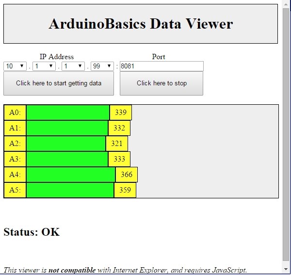
In my case, I programmed the Arduino UNO Web Server to take the following ip address on my internal network: 10.1.1.99

I programmed the Arduino Web Server to listen for Web Browsers on port 8081.
So if I wanted to connect to the Arduino Web Server through my home network, I just had to type in this web address into my web browser: http://10.1.1.99:8081

If you plan to connect to the Arduino using port 80 (which is the default port for web browsers), you can just type the IP address without specifying the port (eg. http://10.1.1.99/ )

The web browser should display the Arduino data in JSON format (the YouTube video above will show you what that looks like).

Once I knew I could connect to the Arduino in my internal network, I then set up port forwarding on my router so that I could type in my external IP address and special port to tunnel my way into my Arduino Web Server on my internal network. This is what I had to do on my router, but you may need to do something different.

  1. My first step was to find out my public/external IP address by typing "what is my IP address" into google. If you want to know your external IP address click here.
  2. I then typed my router's ip address into a web browser, and logged into my router.
  3. I went to the advanced settings tab
  4. Selected "Port Forwarding" from the side menu
  5. Filled out all of the details on the first line of the Ports list
    • Enable box = ticked
    • Description = Arduino
    • WAN interface = pppoe_atm0/ppp0
    • Inbound port = 8082
    • Type = TCP
    • Private IP address = 10.1.1.99
    • Private port = 8081
  6. Saved the settings

Now that I had port forwarding enabled, I could type the ip address (that I obtained in step 1) into my browser and specified port 8082 (instead of 8081) - eg. http://190.11.70.253:8082/

And now I can access my Arduino Web server from anywhere in the world. I can even access it from my smart phone. Once again, this will only return the Analog data in JSON format.


The Web Page GUI

The Arduino is now on the internet, so there are two options. You can either

Instructions on how to use these web pages, are listed below the HTML code.


To retrieve data from your Arduino Web Server, please make sure that it is connected and visible from outside of you local network. You will need to have port forwarding enabled. Information on port forwarding is described above.

  1. Find what your external IP address is.
  2. Enter this address using the IP address drop-down boxes within the "ArduinoBasics Webserver Data viewer" web page
  3. Enter the port forwarding port number (eg. 8082) into the box labelled "Port"
  4. Then click on the "Click here to start getting data" button - you should start to see the bar charts moving and status should be OK
  5. If the bar charts do not move, and the status message says "Failed to get DATA!!" - then the web page was unable to connect to the Arduino for some reason.


Troubleshooting

  • You may want to type in the web address into your web browser, to make sure that data is being retrieved.
  • You can also open the Serial monitor in the Arduino IDE to make sure that an IP address is being displayed
  • Ensure that you have enabled the port forwarding option on your router
  • Have a look at Developer Tools within Google Chrome to help diagnose web page related issues.
  • The web page will not work properly if you use Internet Explorer or if you have javascript disabled within your browser.

Concluding comments

This tutorial showed you how to connect to your Arduino UNO over the internet, and retrieve data in JSON format using jQuery and AJAX. The web page can be modified to suit your own needs, plus it would be more useful if the Arduino was actually monitoring something, rather than logging data from floating pins. It would also be useful if the Arduino could be controlled to blink an LED, or to turn a motor... but I will leave that project for another day. I hope you enjoyed this tutorial - if it helped you in any way, please consider donating a small "tip" into my money jar. Thank you.


If you like this page, please do me a favour and show your appreciation :

 
Visit my ArduinoBasics Google + page.
Follow me on Twitter by looking for ScottC @ArduinoBasics.
I can also be found on Pinterest and Instagram.
Have a look at my videos on my YouTube channel.


This project would not have been possible without WIZnet's collaborative effort.
Please visit their site for more cool Ethernet products.


However, if you do not have a google profile...
Feel free to share this page with your friends in any way you see fit.

CH376S USB Read/Write module

Have you ever wondered if there was a way to store and retrieve data from a USB stick with an Arduino UNO? Most people choose SD cards to store their project data, but you may be surprised there IS a way!
IC Station have a nice little module which allows you store and retrieve your Arduino (or other MCU) project data to a USB stick.
 
I am not too sure why USB storage is not widely used in Arduino projects? These modules are not expensive, they have been around for quite a while, and are relatively simple to use. You do not need any libraries to get them to work, however, I must say that documentation for this module is not that easy to find. This site and this document proved to be very useful in my endevour to get this module working, and I hope my tutorial below will help you get started and bridge some of the information gaps.
 
The "CH376S USB read/write module" has a CH376S chip onboard which does most of the hard work for you. All you have to do is send the module some commands from the Arduino and the CH376S chip will do the rest. You can communicate with the module in three different ways:

  • Parallel communication
  • SPI communication
  • and Serial (UART) communication.

This project will show you the connections and code for the Serial (UART) communication method only.


Parts Required:

Remove the Jumper

When the CH376S USB module arrives in it's package, it will have a jumper between the TXD pin and GND. You will need to remove this jumper to make the necessary connections between the Arduino UNO and the CH376S USB module.


Fritzing Sketch

Please note, that the Arduino Sketch makes use of the Arduino UNO's onboard LED on digital pin 13. The Fritzing sketch below shows an LED + 300 ohm resistor on a breadboard. This is optional. The LED is not a necessary component of CH376S module communication.

Also be aware that the CH376S USB module has an onboard LED just above the TXD and GND pins near the USB port. This LED will only turn on providing the CH376S module is in USB mode AND a USB device has been inserted into the USB port. Both conditions must be met before the module's onboard LED will illuminate. You will not see the LED turn on just by powering the board.
 
The wire diagram below is the correct setup for Serial communication between an Arduino UNO and the CH376S module. If you wish to use SPI or Parallel communication, you will need to refer to the datasheet.


Arduino Sketch


  1
2
3
4
5
6
7
8
9
10
11
12
13
14
15
16
17
18
19
20
21
22
23
24
25
26
27
28
29
30
31
32
33
34
35
36
37
38
39
40
41
42
43
44
45
46
47
48
49
50
51
52
53
54
55
56
57
58
59
60
61
62
63
64
65
66
67
68
69
70
71
72
73
74
75
76
77
78
79
80
81
82
83
84
85
86
87
88
89
90
91
92
93
94
95
96
97
98
99
100
101
102
103
104
105
106
107
108
109
110
111
112
113
114
115
116
117
118
119
120
121
122
123
124
125
126
127
128
129
130
131
132
133
134
135
136
137
138
139
140
141
142
143
144
145
146
147
148
149
150
151
152
153
154
155
156
157
158
159
160
161
162
163
164
165
166
167
168
169
170
171
172
173
174
175
176
177
178
179
180
181
182
183
184
185
186
187
188
189
190
191
192
193
194
195
196
197
198
199
200
201
202
203
204
205
206
207
208
209
210
211
212
213
214
215
216
217
218
219
220
221
222
223
224
225
226
227
228
229
230
231
232
233
234
235
236
237
238
239
240
241
242
243
244
245
246
247
248
249
250
251
252
253
254
255
256
257
258
259
260
261
262
263
264
265
266
267
268
269
270
271
272
273
274
275
276
277
278
279
280
281
282
283
284
285
286
287
288
289
290
291
292
293
294
295
296
297
298
299
300
301
302
303
304
305
306
307
308
309
310
311
312
313
314
315
316
317
318
319
320
321
322
323
324
325
326
327
328
329
330
331
332
333
334
335
336
337
338
339
340
341
342
343
344
345
346
347
348
349
350
351
352
353
354
355
356
357
358
359
360
361
362
363
364
365
366
367
368
369
370
371
372
373
374
375
376
377
378
379
380
381
382
383
384
385
386
387
388
389
390
391
392
393
394
395
396
397
398
399
400
401
402
403
404
405
406
407
408
409
410
411
412
413
414
415
416
417
418
419
420
421
422
423
424
425
426
427
428
429
430
431
432
433
434
435
436
437
438
439
440
441
442
443
444
445
446
447
448
449
450
451
452
453
454
455
456
457
458
459
460
461
462
463
464
465
466
467
468
469
470
471
472
473
474
475
476
477
478
479
480
481
482
483
484
485
486
487
488
489
490
491
492
493
494
495
496
497
498
499
500
501
502
503
504
505

/* ===============================================================
      Project: CH376S USB Read/Write Module testing ground
       Author: Scott C
      Created: 1st May 2015
  Arduino IDE: 1.6.2
      Website: http://arduinobasics.blogspot.com/p/arduino-basics-projects-page.html
  Description: This project will allow you to perform many of the functions available on the CH376S module.
               Checking connection to the module, putting the module into USB mode, resetting the module, 
               reading, writing, appending text to files on the USB stick. This is very useful alternative to
               SD card modules, plus it doesn't need any libraries.
================================================================== */

#include <SoftwareSerial.h>

byte computerByte; //used to store data coming from the computer
byte USB_Byte; //used to store data coming from the USB stick
int LED = 13; //the LED is connected to digital pin 13
int timeOut = 2000; //TimeOut is 2 seconds. This is the amount of time you wish to wait for a response from the CH376S module.
String wrData = "What is the meaning of life ?"; //We will write this data to a newly created file.
String wrData2 = "42"; //We will append this data to an already existing file.

SoftwareSerial USB(10, 11); // Digital pin 10 on Arduino (RX) connects to TXD on the CH376S module
                                                      // Digital pin 11 on Arduino (TX) connects to RXD on the CH376S module
                                                      // GND on Arduino to GND on CH376S module
                                                      // 5V on Arduino to 5V on CH376S module
//==============================================================================================================================================
void setup() {
  Serial.begin(9600); // Setup serial communication with the computer (using a baud rate of 9600 on serial monitor)
  USB.begin(9600); // Setup serial communication with the CH376S module (using the default baud rate of 9600)
  pinMode(LED,OUTPUT); // Define digital pin 13 as an OUTPUT pin - so that we can use it with an LED
  digitalWrite(LED,LOW); // Turn off the LED
}

//================================================================================================================================================
void loop() {
  if(Serial.available()){
    computerByte = Serial.read(); //read any incoming bytes from the Serial monitor, and store this byte in the variable called computerByte
    if(computerByte==49){ //1 //If you send the number 1 from the serial monitor, the arduino will read it as digital number 49. Google "ascii table" for more info.
      printCommandHeader("COMMAND1: CHECK CONNECTION");
      checkConnection(0x01);                           // Check for successful connection and communication with the CH376S module.
    } 
    if(computerByte==50){ //2
     printCommandHeader("COMMAND2: set_USB_Mode");
      set_USB_Mode(0x06);                              // Code used to enable read/write communication and monitoring of the USB stick
    }
    if(computerByte==51){ //3
      printCommandHeader("COMMAND3: resetALL");
      resetALL();                                      // Reset the USB device
    }
    if(computerByte==52){ //4
      printCommandHeader("COMMAND4: Create and Write to File : TEST4.TXT");
      writeFile("TEST4.TXT", wrData); // Create a file called TEST4.TXT and then Write the contents of wrData to this file
    }
    if(computerByte==53){ //5
      printCommandHeader("COMMAND5: Read File: TEST4.TXT");
      readFile("TEST4.TXT"); // Read the contents of this file on the USB disk, and display contents in the Serial Monitor
    }
    if(computerByte==54){ //6
      printCommandHeader("COMMAND6: Append data to file: TEST4.TXT");
      appendFile("TEST4.TXT", wrData2); // Append data to the end of the file.
    }
    if(computerByte==55){ //7
      printCommandHeader("COMMAND7: Delete File: TEST4.TXT");
      fileDelete("TEST4.TXT"); // Delete the file named TEST4.TXT
    }
    if(computerByte==56){ //8
      printCommandHeader("COMMAND8: Read File: TEST2.TXT");
      readFile("TEST2.TXT"); // Read the contents of the TEST2.TXT file on the USB disk, and display contents in the Serial Monitor
    }
    if(computerByte==57){ //9
      printCommandHeader("COMMAND9: Read File: TEST3.TXT");
      readFile("TEST3.TXT"); // Read the contents of the TEST3.TXT file on the USB disk, and display contents in the Serial Monitor
    }
  }
  
  if(USB.available()){ // This is here to capture any unexpected data transmitted by the CH376S module
    Serial.print("CH376S has just sent this code:");
    Serial.println(USB.read(), HEX);
  }
}

//END OF LOOP FUNCTION ========================================================================================================================================

//print Command header
void printCommandHeader(String header){
   Serial.println("======================");
   Serial.println("");
   Serial.println(header);
   Serial.println("----------------------");
}

//checkConnection==================================================================================
//This function is used to check for successful communication with the CH376S module. This is not dependant of the presence of a USB stick.
//Send any value between 0 to 255, and the CH376S module will return a number = 255 - value. 
void checkConnection(byte value){
  USB.write(0x57);
  USB.write(0xAB);
  USB.write(0x06);
  USB.write(value);
  
  if(waitForResponse("checking connection")){ //wait for a response from the CH376S. If CH376S responds, it will be true. If it times out, it will be false.
    if(getResponseFromUSB()==(255-value)){
       Serial.println(">Connection to CH376S was successful.");
       blinkLED();                               //blink the LED for 1 second if the connection was successful
    } else {
      Serial.print(">Connection to CH376S - FAILED.");
    }
  }
}

//set_USB_Mode=====================================================================================
//Make sure that the USB is inserted when using 0x06 as the value in this specific code sequence
void set_USB_Mode (byte value){
  USB.write(0x57);
  USB.write(0xAB);
  USB.write(0x15);
  USB.write(value);
  
  delay(20);
  
  if(USB.available()){
    USB_Byte=USB.read();
    //Check to see if the command has been successfully transmitted and acknowledged.
    if(USB_Byte==0x51){ // If true - the CH376S has acknowledged the command.
        Serial.println("set_USB_Mode command acknowledged"); //The CH376S will now check and monitor the USB port
        USB_Byte = USB.read();
        
        //Check to see if the USB stick is connected or not.
        if(USB_Byte==0x15){ // If true - there is a USB stick connected
          Serial.println("USB is present");
          blinkLED();                                     // If the process was successful, then turn the LED on for 1 second
        } else {
          Serial.print("USB Not present. Error code:"); // If the USB is not connected - it should return an Error code = FFH
          Serial.print(USB_Byte, HEX);
          Serial.println("H");
        }
        
    } else {
        Serial.print("CH3765 error! Error code:");
        Serial.print(USB_Byte, HEX);
        Serial.println("H");
    }   
  }
  delay(20);
}

//resetALL=========================================================================================
//This will perform a hardware reset of the CH376S module - which usually takes about 35 msecs =====
void resetALL(){
    USB.write(0x57);
    USB.write(0xAB);
    USB.write(0x05);
    Serial.println("The CH376S module has been reset !");
    delay(200);
}

//readFile=====================================================================================
//This will send a series of commands to read data from a specific file (defined by fileName)
void readFile(String fileName){
  resetALL();                     //Reset the module
  set_USB_Mode(0x06);             //Set to USB Mode
  diskConnectionStatus();         //Check that communication with the USB device is possible
  USBdiskMount();                 //Prepare the USB for reading/writing - you need to mount the USB disk for proper read/write operations.
  setFileName(fileName);          //Set File name
  fileOpen();                     //Open the file for reading
  int fs = getFileSize(); //Get the size of the file
  fileRead();                     //***** Send the command to read the file ***
  fileClose(0x00);                //Close the file
}

//writeFile========================================================================================
//is used to create a new file and then write data to that file. "fileName" is a variable used to hold the name of the file (e.g TEST.TXT). "data" should not be greater than 255 bytes long. 
void writeFile(String fileName, String data){
  resetALL();                     //Reset the module
  set_USB_Mode(0x06);             //Set to USB Mode
  diskConnectionStatus();         //Check that communication with the USB device is possible
  USBdiskMount();                 //Prepare the USB for reading/writing - you need to mount the USB disk for proper read/write operations.
  setFileName(fileName);          //Set File name
  if(fileCreate()){ //Try to create a new file. If file creation is successful
    fileWrite(data);              //write data to the file.
  } else {
    Serial.println("File could not be created, or it already exists");
  }
  fileClose(0x01);
}

//appendFile()====================================================================================
//is used to write data to the end of the file, without erasing the contents of the file.
void appendFile(String fileName, String data){
    resetALL();                     //Reset the module
    set_USB_Mode(0x06);             //Set to USB Mode
    diskConnectionStatus();         //Check that communication with the USB device is possible
    USBdiskMount();                 //Prepare the USB for reading/writing - you need to mount the USB disk for proper read/write operations.
    setFileName(fileName);          //Set File name
    fileOpen();                     //Open the file
    filePointer(false); //filePointer(false) is to set the pointer at the end of the file. filePointer(true) will set the pointer to the beginning.
    fileWrite(data);                //Write data to the end of the file
    fileClose(0x01);                //Close the file using 0x01 - which means to update the size of the file on close.
}
  
//setFileName======================================================================================
//This sets the name of the file to work with
void setFileName(String fileName){
  Serial.print("Setting filename to:");
  Serial.println(fileName);
  USB.write(0x57);
  USB.write(0xAB);
  USB.write(0x2F);
  USB.write(0x2F); // Every filename must have this byte to indicate the start of the file name.
  USB.print(fileName); // "fileName" is a variable that holds the name of the file. eg. TEST.TXT
  USB.write((byte)0x00); // you need to cast as a byte - otherwise it will not compile. The null byte indicates the end of the file name.
  delay(20);
}

//diskConnectionStatus================================================================================
//Check the disk connection status
void diskConnectionStatus(){
  Serial.println("Checking USB disk connection status");
  USB.write(0x57);
  USB.write(0xAB);
  USB.write(0x30);

  if(waitForResponse("Connecting to USB disk")){ //wait for a response from the CH376S. If CH376S responds, it will be true. If it times out, it will be false.
    if(getResponseFromUSB()==0x14){ //CH376S will send 0x14 if this command was successful
       Serial.println(">Connection to USB OK");
    } else {
      Serial.print(">Connection to USB - FAILED.");
    }
  }
}

//USBdiskMount========================================================================================
//initialise the USB disk and check that it is ready - this process is required if you want to find the manufacturing information of the USB disk
void USBdiskMount(){
  Serial.println("Mounting USB disk");
  USB.write(0x57);
  USB.write(0xAB);
  USB.write(0x31);

  if(waitForResponse("mounting USB disk")){ //wait for a response from the CH376S. If CH376S responds, it will be true. If it times out, it will be false.
    if(getResponseFromUSB()==0x14){ //CH376S will send 0x14 if this command was successful
       Serial.println(">USB Mounted - OK");
    } else {
      Serial.print(">Failed to Mount USB disk.");
    }
  }
}

//fileOpen========================================================================================
//opens the file for reading or writing
void fileOpen(){
  Serial.println("Opening file.");
  USB.write(0x57);
  USB.write(0xAB);
  USB.write(0x32);
  if(waitForResponse("file Open")){ //wait for a response from the CH376S. If CH376S responds, it will be true. If it times out, it will be false.
    if(getResponseFromUSB()==0x14){ //CH376S will send 0x14 if this command was successful
       Serial.println(">File opened successfully.");
    } else {
      Serial.print(">Failed to open file.");
    }
  }
}

//setByteRead=====================================================================================
//This function is required if you want to read data from the file. 
boolean setByteRead(byte numBytes){
  boolean bytesToRead=false;
  int timeCounter = 0;
  USB.write(0x57);
  USB.write(0xAB);
  USB.write(0x3A);
  USB.write((byte)numBytes); //tells the CH376S how many bytes to read at a time
  USB.write((byte)0x00);
  if(waitForResponse("setByteRead")){ //wait for a response from the CH376S. If CH376S responds, it will be true. If it times out, it will be false.
    if(getResponseFromUSB()==0x1D){ //read the CH376S message. If equal to 0x1D, data is present, so return true. Will return 0x14 if no data is present.
      bytesToRead=true;
    }
  }
  return(bytesToRead);


//getFileSize()===================================================================================
//writes the file size to the serial Monitor.
int getFileSize(){
  int fileSize=0;
  Serial.println("Getting File Size");
  USB.write(0x57);
  USB.write(0xAB);
  USB.write(0x0C);
  USB.write(0x68);
  delay(100);
  Serial.print("FileSize =");
  if(USB.available()){
    fileSize = fileSize + USB.read();
  } 
  if(USB.available()){
    fileSize = fileSize + (USB.read()*255);
  } 
  if(USB.available()){
    fileSize = fileSize + (USB.read()*255*255);
  } 
  if(USB.available()){
    fileSize = fileSize + (USB.read()*255*255*255);
  }     
  Serial.println(fileSize);
  delay(10);
  return(fileSize);
}


//fileRead========================================================================================
//read the contents of the file
void fileRead(){
  Serial.println("Reading file:");
  byte firstByte = 0x00; //Variable to hold the firstByte from every transmission. Can be used as a checkSum if required.
  byte numBytes = 0x40; //The maximum value is 0x40 = 64 bytes
 
  while(setByteRead(numBytes)){ //This tells the CH376S module how many bytes to read on the next reading step. In this example, we will read 0x10 bytes at a time. Returns true if there are bytes to read, false if there are no more bytes to read.
    USB.write(0x57);
    USB.write(0xAB);
    USB.write(0x27); //Command to read ALL of the bytes (allocated by setByteRead(x))
    if(waitForResponse("reading data")){ //Wait for the CH376S module to return data. TimeOut will return false. If data is being transmitted, it will return true.
        firstByte=USB.read(); //Read the first byte
        while(USB.available()){
          Serial.write(USB.read()); //Send the data from the USB disk to the Serial monitor
          delay(1); //This delay is necessary for successful Serial transmission
        }
    }
    if<!continueRead()){><span>//prepares the module for further reading. If false, stop reading.</span><br />      <span>break</span>; <span>//You need the continueRead() method if the data to be read from the USB device is greater than numBytes.</span><br />    }<br />  }<br />  <span><b>Serial</b></span>.<span>println</span>();<br />  <span><b>Serial</b></span>.<span>println</span>(<span>"NO MORE DATA"</span>);<br />}<br /><br /><span>//fileWrite=======================================================================================</span><br /><span>//are the commands used to write to the file</span><br /><span>void</span> fileWrite(<span>String</span> data){<br />  <span><b>Serial</b></span>.<span>println</span>(<span>"Writing to file:"</span>);<br />  <span>byte</span> dataLength = (<span>byte</span>) data.<span>length</span>(); <span>// This variable holds the length of the data to be written (in bytes)</span><br />  <span><b>Serial</b></span>.<span>println</span>(data);<br />  <span><b>Serial</b></span>.<span>print</span>(<span>"Data Length:"</span>);<br />  <span><b>Serial</b></span>.<span>println</span>(dataLength);<br />  <span>delay</span>(100);<br />  <span>// This set of commands tells the CH376S module how many bytes to expect from the Arduino. (defined by the "dataLength" variable)</span><br />  USB.<span>write</span>(0x57);<br />  USB.<span>write</span>(0xAB);<br />  USB.<span>write</span>(0x3C);<br />  USB.<span>write</span>((<span>byte</span>) dataLength);<br />  USB.<span>write</span>((<span>byte</span>) 0x00);<br />  <span>if</span>(waitForResponse(<span>"setting data Length"</span>)){ <span>// Wait for an acknowledgement from the CH376S module before trying to send data to it</span><br />    <span>if</span>(getResponseFromUSB()==0x1E){ <span>// 0x1E indicates that the USB device is in write mode.</span><br />      USB.<span>write</span>(0x57);<br />      USB.<span>write</span>(0xAB);<br />      USB.<span>write</span>(0x2D);<br />      USB.<span>print</span>(data); <span>// write the data to the file</span><br />  <br />      <span>if</span>(waitForResponse(<span>"writing data to file"</span>)){ <span>// wait for an acknowledgement from the CH376S module</span><br />      }<br />      <span><b>Serial</b></span>.<span>print</span>(<span>"Write code (normally FF and 14): "</span>);<br />      <span><b>Serial</b></span>.<span>print</span>(USB.<span>read</span>(),<span>HEX</span>); <span>// code is normally 0xFF</span><br />      <span><b>Serial</b></span>.<span>print</span>(<span>","</span>);<br />      USB.<span>write</span>(0x57);<br />      USB.<span>write</span>(0xAB);<br />      USB.<span>write</span>(0x3D); <span>// This is used to update the file size. Not sure if this is necessary for successful writing.</span><br />      <span>if</span>(waitForResponse(<span>"updating file size"</span>)){ <span>// wait for an acknowledgement from the CH376S module</span><br />      }<br />      <span><b>Serial</b></span>.<span>println</span>(USB.<span>read</span>(),<span>HEX</span>); <span>//code is normally 0x14</span><br />    }<br />  }<br />}<br /><br /><span>//continueRead()==================================================================================</span><br /><span>//continue to read the file : I could not get this function to work as intended.</span><br /><span>boolean</span> continueRead(){<br />  <span>boolean</span> readAgain = <span>false</span>;<br />  USB.<span>write</span>(0x57);<br />  USB.<span>write</span>(0xAB);<br />  USB.<span>write</span>(0x3B);<br />  <span>if</span>(waitForResponse(<span>"continueRead"</span>)){ <span>//wait for a response from the CH376S. If CH376S responds, it will be true. If it times out, it will be false.</span><br />     <span>if</span>(getResponseFromUSB()==0x14){ <span>//CH376S will send 0x14 if this command was successful</span><br />       readAgain=<span>true</span>;<br />     }<br />  }<br />  <span>return</span>(readAgain);<br />} <br /><br /><span>//fileCreate()========================================================================================</span><br /><span>//the command sequence to create a file</span><br /><span>boolean</span> fileCreate(){<br />  <span>boolean</span> createdFile = <span>false</span>;<br />  USB.<span>write</span>(0x57);<br />  USB.<span>write</span>(0xAB);<br />  USB.<span>write</span>(0x34);<br />  <span>if</span>(waitForResponse(<span>"creating file"</span>)){ <span>//wait for a response from the CH376S. If file has been created successfully, it will return true.</span><br />     <span>if</span>(getResponseFromUSB()==0x14){ <span>//CH376S will send 0x14 if this command was successful</span><br />       createdFile=<span>true</span>;<br />     }<br />  }<br />  <span>return</span>(createdFile);<br />}<br /><br /><br /><span>//fileDelete()========================================================================================</span><br /><span>//the command sequence to delete a file</span><br /><span>void</span> fileDelete(<span>String</span> fileName){<br />  setFileName(fileName);<br />  <span>delay</span>(20);<br />  USB.<span>write</span>(0x57);<br />  USB.<span>write</span>(0xAB);<br />  USB.<span>write</span>(0x35);<br />  <span>if</span>(waitForResponse(<span>"deleting file"</span>)){ <span>//wait for a response from the CH376S. If file has been created successfully, it will return true.</span><br />     <span>if</span>(getResponseFromUSB()==0x14){ <span>//CH376S will send 0x14 if this command was successful</span><br />       <span><b>Serial</b></span>.<span>println</span>(<span>"Successfully deleted file"</span>);<br />     }<br />  }<br />}<br />  <br /><br /><span>//filePointer========================================================================================</span><br /><span>//is used to set the file pointer position. true for beginning of file, false for the end of the file.</span><br /><span>void</span> filePointer(<span>boolean</span> fileBeginning){<br />  USB.<span>write</span>(0x57);<br />  USB.<span>write</span>(0xAB);<br />  USB.<span>write</span>(0x39);<br />  <span>if</span>(fileBeginning){<br />    USB.<span>write</span>((<span>byte</span>)0x00); <span>//beginning of file</span><br />    USB.<span>write</span>((<span>byte</span>)0x00);<br />    USB.<span>write</span>((<span>byte</span>)0x00);<br />    USB.<span>write</span>((<span>byte</span>)0x00);<br />  } <span>else</span> {<br />    USB.<span>write</span>((<span>byte</span>)0xFF); <span>//end of file</span><br />    USB.<span>write</span>((<span>byte</span>)0xFF);<br />    USB.<span>write</span>((<span>byte</span>)0xFF);<br />    USB.<span>write</span>((<span>byte</span>)0xFF);<br />  }<br />  <span>if</span>(waitForResponse(<span>"setting file pointer"</span>)){ <span>//wait for a response from the CH376S. </span><br />     <span>if</span>(getResponseFromUSB()==0x14){ <span>//CH376S will send 0x14 if this command was successful</span><br />       <span><b>Serial</b></span>.<span>println</span>(<span>"Pointer successfully applied"</span>);<br />     }<br />  }<br />}<br /><br /><br /><span>//fileClose=======================================================================================</span><br /><span>//closes the file</span><br /><span>void</span> fileClose(<span>byte</span> closeCmd){<br />  <span><b>Serial</b></span>.<span>println</span>(<span>"Closing file:"</span>);<br />  USB.<span>write</span>(0x57);<br />  USB.<span>write</span>(0xAB);<br />  USB.<span>write</span>(0x36);<br />  USB.<span>write</span>((<span>byte</span>)closeCmd); <span>// closeCmd = 0x00 = close without updating file Size, 0x01 = close and update file Size</span><br /><br />  <span>if</span>(waitForResponse(<span>"closing file"</span>)){ <span>// wait for a response from the CH376S. </span><br />     <span>byte</span> resp = getResponseFromUSB();<br />     <span>if</span>(resp==0x14){ <span>// CH376S will send 0x14 if this command was successful</span><br />       <span><b>Serial</b></span>.<span>println</span>(<span>">File closed successfully."</span>);<br />     } <span>else</span> {<br />       <span><b>Serial</b></span>.<span>print</span>(<span>">Failed to close file. Error code:"</span>);<br />       <span><b>Serial</b></span>.<span>println</span>(resp, <span>HEX</span>);<br />     }  <br />  }<br />}<br /><br /><span>//waitForResponse===================================================================================</span><br /><span>//is used to wait for a response from USB. Returns true when bytes become available, false if it times out.</span><br /><span>boolean</span> waitForResponse(<span>String</span> errorMsg){<br />  <span>boolean</span> bytesAvailable = <span>true</span>;<br />  <span>int</span> counter=0;<br />  <span>while</span><!USB><span>available</span>()){ <span>//wait for CH376S to verify command</span><br />    <span>delay</span>(1);<br />    counter++;<br />    <span>if</span>(counter>timeOut){<br />      <span><b>Serial</b></span>.<span>print</span>(<span>"TimeOut waiting for response: Error while: "</span>);<br />      <span><b>Serial</b></span>.<span>println</span>(errorMsg);<br />      bytesAvailable = <span>false</span>;<br />      <span>break</span>;<br />    }<br />  }<br />  <span>delay</span>(1);<br />  <span>return</span>(bytesAvailable);<br />}<br /><br /><span>//getResponseFromUSB================================================================================</span><br /><span>//is used to get any error codes or messages from the CH376S module (in response to certain commands)</span><br /><span>byte</span> getResponseFromUSB(){<br />  <span>byte</span> response = <span>byte</span>(0x00);<br />  <span>if</span> (USB.<span>available</span>()){<br />    response = USB.<span>read</span>();<br />  }<br />  <span>return</span>(response);<br />}<br /><br /><br /><br /><span>//blinkLED==========================================================================================</span><br /><span>//Turn an LED on for 1 second</span><br /><span>void</span> blinkLED(){<br />  <span>digitalWrite</span>(LED, <span>HIGH</span>);<br />  <span>delay</span>(1000);<br />  <span>digitalWrite</span>(LED,<span>LOW</span>);<br />}<br /><br /></pre> </td> </tr> </table></div></p> <br /> <p> If you copy and paste this code directly into the Arduino IDE; you may get a warning like this when you compile the code:<br />   <br />    "Low memory available, stability problems may occur". <br />  <br /> I managed to run the sketch without any issues, however, I did experience problems with some of the methods when I had made further memory hungry modifications. If you do encounter problems, I would recommend that you eliminate any methods which you do not plan to use, and perhaps reduce the number of Serial.print statements throughout the code. However, please note that some of the methods will not work unless the module is in the correct state, so be careful which methods you delete. For example, I found that I could get some simple functionality without the "USBdiskMount()" method. However, I could not read/write data beyond a certain length without this method.<br />   <br /> Also please note, that some of the methods called within the reading and writing sequence do not need to be called every time. They can be called once in setup, while other methods within the sequence will need to be called every time. I grouped them all together for simplicity. </p> <!--separator --><img src="https://images-blogger-opensocial.googleusercontent.com/gadgets/proxy?url=http%3A%2F%2F1.bp.blogspot.com%2F-XQiwNpdqOxk%2FT_rKCzDh4nI%2FAAAAAAAAAQY%2FOfYBljhU6Lk%2Fs1600%2FSeparator.jpg&container=blogger&gadget=a&rewriteMime=image%2F*" /><br /> <p><h4>Serial Commands</h4> Have a look at the following presentation for a summary of the Serial commands used in this tutorial: <br />   <br /> <div> </div> </p> </div><p> <div> <!-- Concluding Comments --> </div> <br />  <br />  <div> <p> <!--separator --> <img src="https://images-blogger-opensocial.googleusercontent.com/gadgets/proxy?url=http%3A%2F%2F1.bp.blogspot.com%2F-XQiwNpdqOxk%2FT_rKCzDh4nI%2FAAAAAAAAAQY%2FOfYBljhU6Lk%2Fs1600%2FSeparator.jpg&container=blogger&gadget=a&rewriteMime=image%2F*" /><br /> <br /> </p> </div> </p><p> <div> If you like this page, please do me a favour and show your appreciation : <br /> <br />  <br /> Visit my <a href="https://plus.google.com/u/0/b/107402020974762902161/107402020974762902161/posts">ArduinoBasics Google + page</a>.<br /> Follow me on Twitter by looking for <a href="https://twitter.com/ArduinoBasics">ScottC @ArduinoBasics</a>.<br /> I can also be found on <a href="https://www.pinterest.com/ArduinoBasics/">Pinterest</a> and <a href="https://instagram.com/arduinobasics">Instagram</a>. <br /> Have a look at my videos on my <a href="https://www.youtube.com/user/ScottCMe/videos">YouTube channel</a>.<br /> </div> </p> <br /> <div> <p> <!--separator --> <img src="https://images-blogger-opensocial.googleusercontent.com/gadgets/proxy?url=http%3A%2F%2F1.bp.blogspot.com%2F-XQiwNpdqOxk%2FT_rKCzDh4nI%2FAAAAAAAAAQY%2FOfYBljhU6Lk%2Fs1600%2FSeparator.jpg&container=blogger&gadget=a&rewriteMime=image%2F*" /><br /> <br /> </p> </div> <p> However, if you do not have a google profile... <br />Feel free to share this page with your friends in any way you see fit. </p>

Rocket Scientists Are Arduino at Heart

This is the story of a group of college students who moved to the Mojave Desert, bought a house, painted it white, and turned it into a make-shift lab. Then they went out to launch rockets.

Read more on MAKE

Online data analysis with Arduino and plotly

Introduction

It’s 2014 and the Internet-of-Things is flying along at a rapid rate with all sorts of services and devices that share data and allow control via the Internet. In the spirit of this we look a new service called plotly.

This is a “collaborative data analysis and graphing tool” which allows you to upload your own data to be analysed in many ways, and then graph the results using all sorts of plot types.

With plotly you can run your own mathematical functions over your data, run intense statistical analysis and use or edit one of the many APIs (PythonMATLABRJuliaRESTArduino, or Perl) to increase the level of customisation. Plotly works in conjunction with Google Drive to store your data, however this can be exported and imported without any issues. Futhermore plotly works best in Google Chrome.

For our review we’ll look at using plotly to quickly display and analyse data received from an Internet-connected Arduino – our EtherTen, or you can use almost any Arduino and Ethernet shield. The system isn’t completely documented however by revieiwng our example sketch and some experimenting with the interface plotly is very much usable, even in its current beta format.

Getting started with plotly

You will need to setup a plotly account, and this is simply accomplished from their main site. Some of you may be wondering what plotly costs – at the time of writing plotly is free for unlimited public use (that is – anyone can see your data with the right URL), but requires a subscription for extended private use. You can find the costs at the plans page.

Once you have a plotly account, visit your plotly home page, whose URL is https://plot.ly/~yourusername/# – then click “edit profile”. Another window will appear which amongst other things contains your plotly API key – make a note of this as you will need it and your username for the Arduino sketch.

Next, you’ll need some Arduino or compatible hardware to capture the data to log and analyse. An Arduino with an Ethernet or WiFi connection, and appropriate sensors for your application. We have our EtherTen that takes readings from a temperature/humidity sensor and a light level sensor:

Now you need a new Arduino library, which is available from the plotly API page. Lots of APIs there… Anyhow, click “Arduino” and you will arrive at the github page. Download the entire .zip file, and extract the plotly_ethernet folder into Arduino libraries folder which in most installations can be found at ..Arduino-1.0.xlibraries. 

Finally we’ll use a demonstration sketch provided by plotly and modify this to our needs, which can be downloaded from github. We’ll go through this sketch and show you what to update – so have a quick look and then at out example sketch at the end of this section.

First, insert any code required to get data from your sensors and store the data in a variable – do this so the values can be used in void loop. Next, update the MAC address and the IP address of your Ethernet-enabled Arduino with the following lines:

byte mac[] = { 0xDE, 0xAD, 0xBE, 0xEF, 0xFE, 0xED };
byte my_ip[] = { 192,168,0,77 };

and change the MAC and IP if necessary. If Arduino and Ethernet is new to you, check out the tutorial. Now look for the following two lines and enter your plotly username and API key:

plotly.username = "yourplotlyusername";
plotly.api_key = "yourplotlyAPIkey";

Next – it’s a good idea to set your time zone, so the time in plots makes sense. Add the following two lines in void setup():

plotly.timestamp = true; 
plotly.timezone = "Australia/Melbourne";

You can find a list of time zones available for use with plotly here. Now you need to determine how many traces and points to use. A trace is one source of data, for example temperature. For now you will have one point, so set these parameters using the following lines:

int nTraces=x; // x = number of traces
int nPoints=1;

For example, we will plot temperature, humidity and light level – so this requires three traces. The next step is to set the filename for the plot, using the following line:

char filename[] = "simple_example";

This will be sent to plotly and your data will be saved under that name. At the point in your sketch where you want to send some data back to plotly, use:

plotly.open_stream(nPoints, nTraces, filename, layout);

… then the following for each trace:

plotly.post(millis(),data);

where data is the variable to send back to plotly. We use millis() as our example is logging data against time.

To put all that together, consider our example sketch with the hardware mentioned earlier:

// Code modified from example provied by plot.ly

#include <SPI.h>
#include <Ethernet.h>
#include "plotly_ethernet.h"
#include "DHT.h"

// DHT Sensor Setup
#define DHTPIN 2               // We have connected the DHT to Digital Pin 2
#define DHTTYPE DHT22          // This is the type of DHT Sensor (Change it to DHT11 if you're using that model)
DHT dht(DHTPIN, DHTTYPE);      // Initialize DHT object
plotly plotly;                 // initialize a plotly object, named plotly

//initialize plotly global variables
char layout[]="{}";
char filename[] = "Office Weather and Light"; // name of the plot that will be saved in your plotly account -- resaving to the same filename will simply extend the existing traces with new data

float h, t, ll;
int lightLevel;

// Ethernet Setup
byte mac[] = { 0xDE, 0xAD, 0xBE, 0xEF, 0xFE, 0xED }; // doesn't really matter
byte my_ip[] = { 192, 168, 1, 77 }; // google will tell you: "public ip address"

void startEthernet(){
  Serial.println("Initializing ethernet");
  if(Ethernet.begin(mac) == 0){
    Serial.println("Failed to configure Ethernet using DHCP");
    // no point in carrying on, so do nothing forevermore:
    // try to congifure using IP address instead of DHCP:
    Ethernet.begin(mac, my_ip);
  }
  Serial.println("Done initializing ethernet");
  delay(1000);
}

void setup() {
  // Open serial communications and wait for port to open:
  Serial.begin(9600);
  while (!Serial) {
    ; // wait for serial port to connect. Needed for Leonardo only
  }

  dht.begin(); // initialize dht sensor reading
  startEthernet();    // initialize ethernet

    // Initialize plotly settings
  plotly.VERBOSE = true; // turn to false to suppress printing over serial
  plotly.DRY_RUN = false; // turn to false when you want to connect to plotly's servers 
  plotly.username = "yourplotlyusername"; // your plotly username -- sign up at https://plot.ly/ssu or feel free to use this public account. password of the account is "password"
  plotly.api_key = "yourplotlyapikey"; // "public_arduino"'s api_key -- char api_key[10]
  plotly.timestamp = true; // tell plotly that you're stamping your data with a millisecond counter and that you want plotly to convert it into a date-formatted graph
  plotly.timezone = "Australia/Melbourne"; // full list of timezones is here:https://github.com/plotly/arduino-api/blob/master/Accepted%20Timezone%20Strings.txt
}

void loop() 
{
  // gather data to plot
  h = dht.readHumidity(); // read humitidy from DHT pin
  t = dht.readTemperature();
  lightLevel = analogRead(A5);
  ll = lightLevel / 100; // reduce the value from the light sensor

  // Open the Stream
  plotly.open_stream(1, 3, filename, layout); // plotlystream(number_of_points, number_of_traces, filename, layout)

  plotly.post(millis(),t); // post temperature to plotly (trace 1)
  delay(150);
  plotly.post(millis(),h); // post humidity to plotly (trace 2)
  delay(150);
  plotly.post(millis(),lightLevel); // post light sensor readout to plotly (trace 3)

  for(int i=0; i<300; i++)
  { // (once every five minutes)
    delay(1000);
  }
}

After wiring up the hardware and uploading the sketch, the data will be sent until the power is removed from the Arduino.

Monitoring sensor data

Now that your hardware is sending the data off to plotly, you can check it out in real time. Log into plotly and visit the data home page – https://plot.ly/plot – for example:

Your data file will be listed – so just click on the file name to be presented with a very basic graph. Over time you will see it develop as the data is received, however you may want to alter the display, headings, labels and so on. Generally you can click on trace labels, titles and so on to change them, the interface is pretty intuitive after a few moments. A quick screencast of this is shown in this video.

To view and analyse the raw data – and create all sorts of custom plots, graphs and other analysis – click the “view data in grid” icon which is the second from the left along the bar:

At which point your data will be displayed in a new tab:

From this point you can experiment to your heart’s content – just don’t forget to save your work. In a short amount of time your data can be presented visually and analysed with ease:

Conclusion

Although plotly is still in beta form, it works well and the developers are responsive to any questions – so there isn’t much more to say but give it a try yourself, doing so won’t cost you anything and you can see how useful plotly is for yourself. And if you enjoyed this article, or want to introduce someone else to the interesting world of Arduino – check out my book (now in a third printing!) “Arduino Workshop”.

Have fun and keep checking into tronixstuff.com. Why not follow things on twitterGoogle+, subscribe  for email updates or RSS using the links on the right-hand column, or join our forum – dedicated to the projects and related items on this website. Sign up – it’s free, helpful to each other –  and we can all learn something.
Tronixstuff 21 Jan 05:29
analysis  api  arduino  data  ethernet  internet  iot  of  online  plotly  things  tronixstuff  tutorial  

Online data analysis with Arduino and plotly

Introduction

It’s 2014 and the Internet-of-Things is flying along at a rapid rate with all sorts of services and devices that share data and allow control via the Internet. In the spirit of this we look a new service called plotly.

This is a “collaborative data analysis and graphing tool” which allows you to upload your own data to be analysed in many ways, and then graph the results using all sorts of plot types.

With plotly you can run your own mathematical functions over your data, run intense statistical analysis and use or edit one of the many APIs (PythonMATLABRJuliaRESTArduino, or Perl) to increase the level of customisation. Plotly works in conjunction with Google Drive to store your data, however this can be exported and imported without any issues. Futhermore plotly works best in Google Chrome.

For our review we’ll look at using plotly to quickly display and analyse data received from an Internet-connected Arduino – our EtherTen, or you can use almost any Arduino and Ethernet shield. The system isn’t completely documented however by revieiwng our example sketch and some experimenting with the interface plotly is very much usable, even in its current beta format.

Getting started with plotly

You will need to setup a plotly account, and this is simply accomplished from their main site. Some of you may be wondering what plotly costs – at the time of writing plotly is free for unlimited public use (that is – anyone can see your data with the right URL), but requires a subscription for extended private use. You can find the costs at the plans page.

Once you have a plotly account, visit your plotly home page, whose URL is https://plot.ly/~yourusername/# – then click “edit profile”. Another window will appear which amongst other things contains your plotly API key – make a note of this as you will need it and your username for the Arduino sketch.

Next, you’ll need some Arduino or compatible hardware to capture the data to log and analyse. An Arduino with an Ethernet or WiFi connection, and appropriate sensors for your application. We have our EtherTen that takes readings from a temperature/humidity sensor and a light level sensor:

Now you need a new Arduino library, which is available from the plotly API page. Lots of APIs there… Anyhow, click “Arduino” and you will arrive at the github page. Download the entire .zip file, and extract the plotly_ethernet folder into Arduino libraries folder which in most installations can be found at ..\Arduino-1.0.x\libraries. 

Finally we’ll use a demonstration sketch provided by plotly and modify this to our needs, which can be downloaded from github. We’ll go through this sketch and show you what to update – so have a quick look and then at out example sketch at the end of this section.

First, insert any code required to get data from your sensors and store the data in a variable – do this so the values can be used in void loop. Next, update the MAC address and the IP address of your Ethernet-enabled Arduino with the following lines:

byte mac[] = { 0xDE, 0xAD, 0xBE, 0xEF, 0xFE, 0xED };
byte my_ip[] = { 192,168,0,77 };

and change the MAC and IP if necessary. If Arduino and Ethernet is new to you, check out the tutorial. Now look for the following two lines and enter your plotly username and API key:

plotly.username = "yourplotlyusername";
plotly.api_key = "yourplotlyAPIkey";

Next – it’s a good idea to set your time zone, so the time in plots makes sense. Add the following two lines in void setup():

plotly.timestamp = true; 
plotly.timezone = "Australia/Melbourne";

You can find a list of time zones available for use with plotly here. Now you need to determine how many traces and points to use. A trace is one source of data, for example temperature. For now you will have one point, so set these parameters using the following lines:

int nTraces=x; // x = number of traces
int nPoints=1;

For example, we will plot temperature, humidity and light level – so this requires three traces. The next step is to set the filename for the plot, using the following line:

char filename[] = "simple_example";

This will be sent to plotly and your data will be saved under that name. At the point in your sketch where you want to send some data back to plotly, use:

plotly.open_stream(nPoints, nTraces, filename, layout);

… then the following for each trace:

plotly.post(millis(),data);

where data is the variable to send back to plotly. We use millis() as our example is logging data against time.

To put all that together, consider our example sketch with the hardware mentioned earlier:

// Code modified from example provied by plot.ly

#include <SPI.h>
#include <Ethernet.h>
#include "plotly_ethernet.h"
#include "DHT.h"

// DHT Sensor Setup
#define DHTPIN 2               // We have connected the DHT to Digital Pin 2
#define DHTTYPE DHT22          // This is the type of DHT Sensor (Change it to DHT11 if you're using that model)
DHT dht(DHTPIN, DHTTYPE);      // Initialize DHT object
plotly plotly;                 // initialize a plotly object, named plotly

//initialize plotly global variables
char layout[]="{}";
char filename[] = "Office Weather and Light"; // name of the plot that will be saved in your plotly account -- resaving to the same filename will simply extend the existing traces with new data

float h, t, ll;
int lightLevel;

// Ethernet Setup
byte mac[] = { 0xDE, 0xAD, 0xBE, 0xEF, 0xFE, 0xED }; // doesn't really matter
byte my_ip[] = { 192, 168, 1, 77 }; // google will tell you: "public ip address"

void startEthernet(){
  Serial.println("Initializing ethernet");
  if(Ethernet.begin(mac) == 0){
    Serial.println("Failed to configure Ethernet using DHCP");
    // no point in carrying on, so do nothing forevermore:
    // try to congifure using IP address instead of DHCP:
    Ethernet.begin(mac, my_ip);
  }
  Serial.println("Done initializing ethernet");
  delay(1000);
}

void setup() {
  // Open serial communications and wait for port to open:
  Serial.begin(9600);
  while (!Serial) {
    ; // wait for serial port to connect. Needed for Leonardo only
  }

  dht.begin(); // initialize dht sensor reading
  startEthernet();    // initialize ethernet

    // Initialize plotly settings
  plotly.VERBOSE = true; // turn to false to suppress printing over serial
  plotly.DRY_RUN = false; // turn to false when you want to connect to plotly's servers 
  plotly.username = "yourplotlyusername"; // your plotly username -- sign up at https://plot.ly/ssu or feel free to use this public account. password of the account is "password"
  plotly.api_key = "yourplotlyapikey"; // "public_arduino"'s api_key -- char api_key[10]
  plotly.timestamp = true; // tell plotly that you're stamping your data with a millisecond counter and that you want plotly to convert it into a date-formatted graph
  plotly.timezone = "Australia/Melbourne"; // full list of timezones is here:https://github.com/plotly/arduino-api/blob/master/Accepted%20Timezone%20Strings.txt
}

void loop() 
{
  // gather data to plot
  h = dht.readHumidity(); // read humitidy from DHT pin
  t = dht.readTemperature();
  lightLevel = analogRead(A5);
  ll = lightLevel / 100; // reduce the value from the light sensor

  // Open the Stream
  plotly.open_stream(1, 3, filename, layout); // plotlystream(number_of_points, number_of_traces, filename, layout)

  plotly.post(millis(),t); // post temperature to plotly (trace 1)
  delay(150);
  plotly.post(millis(),h); // post humidity to plotly (trace 2)
  delay(150);
  plotly.post(millis(),lightLevel); // post light sensor readout to plotly (trace 3)

  for(int i=0; i<300; i++)
  { // (once every five minutes)
    delay(1000);
  }
}

After wiring up the hardware and uploading the sketch, the data will be sent until the power is removed from the Arduino.

Monitoring sensor data

Now that your hardware is sending the data off to plotly, you can check it out in real time. Log into plotly and visit the data home page – https://plot.ly/plot – for example:

Your data file will be listed – so just click on the file name to be presented with a very basic graph. Over time you will see it develop as the data is received, however you may want to alter the display, headings, labels and so on. Generally you can click on trace labels, titles and so on to change them, the interface is pretty intuitive after a few moments. A quick screencast of this is shown in this video.

To view and analyse the raw data – and create all sorts of custom plots, graphs and other analysis – click the “view data in grid” icon which is the second from the left along the bar:

At which point your data will be displayed in a new tab:

From this point you can experiment to your heart’s content – just don’t forget to save your work. In a short amount of time your data can be presented visually and analysed with ease:

Conclusion

Although plotly is still in beta form, it works well and the developers are responsive to any questions – so there isn’t much more to say but give it a try yourself, doing so won’t cost you anything and you can see how useful plotly is for yourself. And if you enjoyed this article, or want to introduce someone else to the interesting world of Arduino – check out my book (now in a third printing!) “Arduino Workshop”.

Have fun and keep checking into tronixstuff.com. Why not follow things on twitterGoogle+, subscribe  for email updates or RSS using the links on the right-hand column, or join our forum – dedicated to the projects and related items on this website. Sign up – it’s free, helpful to each other –  and we can all learn something.

The post Online data analysis with Arduino and plotly appeared first on tronixstuff.

Tronixstuff 21 Jan 05:29
analysis  api  arduino  data  ethernet  internet  iot  of  online  plotly  things  tronixstuff  tutorial  

Arduino Tutorials – Chapter 16 – Ethernet

Learn how to connect your Arduino to the outside world via Ethernet

This is chapter sixteen of our huge Arduino tutorial seriesUpdated 06/12/2013

In this chapter we will introduce and examine the use of Ethernet networking with Arduino over local networks and the greater Internet. It will be assumed that you have a basic understanding of computer networking, such as the knowledge of how to connect computers to a hub/router with RJ45 cables, what an IP and MAC address is, and so on. Furthermore, here is a good quick rundown about Ethernet.

Getting Started

You will need an Arduino Uno or compatible board with an Ethernet shield that uses the W5100 Ethernet controller IC (pretty much all of them):

…or consider using a Freetronics EtherTen – as it has everything all on the one board, plus some extras:

Furthermore you will need to power the board via the external DC socket – the W5100 IC uses more current than the USB power can supply. A 9V 1A plug pack/wall wart will suffice. Finally it does get hot – so be careful not to touch the W5100 after extended use. In case you’re not sure – this is the W5100 IC:

Once you have your Ethernet-enabled Arduino, and have the external power connected – it’s a good idea to check it all works. Open the Arduino IDE and selectFile > Examples > Ethernet > Webserver. This loads a simple sketch which will display data gathered from the analogue inputs on a web browser. However don’t upload it yet, it needs a slight modification.

You need to specify the IP address of the Ethernet shield – which is done inside the sketch. This is simple, go to the line:

IPAddress ip(192,168,1, 177);

And alter it to match your own setup. For example, in my home the router’s IP address is 10.1.1.1, the printer is 10.1.1.50 and all PCs are below …50. So I will set my shield IP to 10.1.1.77 by altering the line to:

IPAddress ip(10,1,1,77);

You also have the opportunity to change your MAC address. Each piece of networking equipment has a unique serial number to identify itself over a network, and this is normall hard-programmed into the equipments’ firmware. However with Arduino we can define the MAC address ourselves.

If you are running more than one Ethernet shield on your network, ensure they have different MAC addresses by altering the hexadecimal values in the line:

byte mac[] = { 0xDE, 0xAD, 0xBE, 0xEF, 0xFE, 0xED };

However if you only have one shield just leave it be. There may be the very, very, statistically rare chance of having a MAC address the same as your existing hardware, so that would be another time to change it.

Once you have made your alterations, save and upload the sketch. Now open a web browser and navigate to the IP address you entered in the sketch, and you should be presented with something similar to the following:


What’s happening? The Arduino has been programmed to offer a simple web page with the values measured by the analogue inputs. You can refresh the browser to get updated values.

At this point – please note that the Ethernet shields use digital pins 10~13, so you can’t use those for anything else. Some Arduino Ethernet shields may also have a microSD card socket, which also uses another digital pin – so check with the documentation to find out which one.

Nevertheless, now that we can see the Ethernet shield is working we can move on to something more useful. Let’s dissect the previous example in a simple way, and see how we can distribute and display more interesting data over the network. For reference, all of the Ethernet-related functions are handled by the Ethernet Arduino library. If you examine the previous sketch we just used, the section that will be of interest is:

for (int analogChannel = 0; analogChannel < 6; analogChannel++) 
          {
            int sensorReading = analogRead(analogChannel);
            client.print("analog input ");
            client.print(analogChannel);
            client.print(" is ");
            client.print(sensorReading);
            client.println("<br />");       
          }
          client.println("</html>");

Hopefully this section of the sketch should be familiar – remember how we have used serial.print(); in the past when sending data to the serial monitor box? Well now we can do the same thing, but sending data from our Ethernet shield back to a web browser – on other words, a very basic type of web page.

However there is something you may or may not want to  learn in order to format the output in a readable format – HTML code. I am not a website developer (!) so will not delve into HTML too much.

However if you wish to serve up nicely formatted web pages with your Arduino and so on, here would be a good start. In the interests of simplicity, the following two functions will be the most useful:

client.print(" is ");

Client.print (); allows us to send text or data back to the web page. It works in the same way as serial.print(), so nothing new there. You can also specify the data type in the same way as with serial.print(). Naturally you can also use it to send data back as well. The other useful line is:
client.println("<br />");

which sends the HTML code back to the web browser telling it to start a new line. The part that actually causes the carriage return/new line is the <br /> which is an HTML code (or “tag”) for a new line. So if you are creating more elaborate web page displays, you can just insert other HTML tags in the client.print(); statement. If you want to learn more about HTML commands, here’s a good tutorial site. Finally – note that the sketch will only send the data when it has been requested, that is when it has received a request from the web browser.

Accessing your Arduino over the Internet

So far – so good. But what if you want to access your Arduino from outside the local network?

You will need a static IP address – that is, the IP address your internet service provider assigns to your connection needs to stay the same. If you don’t have a static IP, as long as you leave your modem/router permanently swiched on your IP shouldn’t change. However that isn’t an optimal solution.

If your ISP cannot offer you a static IP at all, you can still move forward with the project by using an organisation that offers a Dynamic DNS. These organisations offer you your own static IP host name (e.g. mojo.monkeynuts.com) instead of a number, keep track of your changing IP address and linking it to the new host name. From what I can gather, your modem needs to support (have an in-built client for…) these DDNS services. As an example, two companies are No-IP andDynDNS.com. Please note that I haven’t used those two, they are just offered as examples.

Now, to find your IP address… usually this can be found by logging into your router’s administration page – it is usually 192.168.0.1 but could be different. Check with your supplier or ISP if they supplied the hardware. For this example, if I enter 10.1.1.1 in a web browser, and after entering my modem administration password, the following screen is presented:

What you are looking for is your WAN IP address, as you can see in the image above. To keep the pranksters away, I have blacked out some of my address.

The next thing to do is turn on port-forwarding. This tells the router where to redirect incoming requests from the outside world. When the modem receives such a request, we want to send that request to the port number of our Ethernet shield. Using the:

EthernetServer server(125);

function in our sketch has set the port number to 125. Each modem’s configuration screen will look different, but as an example here is one:

So you can see from the line number one in the image above, the inbound port numbers have been set to 125, and the IP address of the Ethernet shield has been set to 10.1.1.77 – the same as in the sketch.

After saving the settings, we’re all set. The external address of my Ethernet shield will be the WAN:125, so to access the Arduino I will type my WAN address with :125 at the end into the browser of the remote web device, which will contact the lonely Ethernet hardware back home.

Furthermore, you may need to alter your modem’s firewall settings, to allow the port 125 to be “open” to incoming requests. Please check your modem documentation for more information on how to do this.

Now from basically any Internet connected device in the free world, I can enter my WAN and port number into the URL field and receive the results. For example, from a phone when it is connected to the Internet via LTE mobile data:

So at this stage you can now display data on a simple web page created by your Arduino and access it from anywhere with unrestricted Internet access. With your previous Arduino knowledge (well, this is chapter sixteen) you can now use data from sensors or other parts of a sketch and display it for retrieval.

Displaying sensor data on a web page

As an example of displaying sensor data on a web page, let’s use an inexpensive and popular temperature and humidity sensor – the DHT22. You will need to install the DHT22 Arduino library which can be found on this page. If this is your first time with the DHT22, experiment with the example sketch that’s included with the library so you understand how it works.

Connect the DHT22 with the data pin to Arduino D2, Vin to the 5V pin and GND to … GND:

Now for our sketch – to display the temperature and humidity on a web page. If you’re not up on HTML you can use online services such as this to generate the code, which you can then modify to use in the sketch.

In the example below, the temperature and humidity data from the DHT22 is served in a simple web page:

#include <SPI.h>
#include <Ethernet.h>

// for DHT22 sensor
#include "DHT.h"
#define DHTPIN 2
#define DHTTYPE DHT22

// Enter a MAC address and IP address for your controller below.
// The IP address will be dependent on your local network:
byte mac[] = {   0xDE, 0xAD, 0xBE, 0xEF, 0xFE, 0xED };
IPAddress ip(10,1,1,77);

// Initialize the Ethernet server library
// with the IP address and port you want to use 
// (port 80 is default for HTTP):
EthernetServer server(125);
DHT dht(DHTPIN, DHTTYPE);

void setup() 
{
  dht.begin();
 // Open serial communications and wait for port to open:
  Serial.begin(9600);
   while (!Serial) {
    ; // wait for serial port to connect. Needed for Leonardo only
  }
  // start the Ethernet connection and the server:
  Ethernet.begin(mac, ip);
  server.begin();
  Serial.print("server is at ");
  Serial.println(Ethernet.localIP());
}

void loop() 
{
  // listen for incoming clients
  EthernetClient client = server.available();
  if (client) {
    Serial.println("new client");
    // an http request ends with a blank line
    boolean currentLineIsBlank = true;
    while (client.connected()) {
      if (client.available()) {
        char c = client.read();
        Serial.write(c);
        // if you've gotten to the end of the line (received a newline
        // character) and the line is blank, the http request has ended,
        // so you can send a reply
        if (c == '\n' && currentLineIsBlank) 
        {
          // send a standard http response header
          client.println("HTTP/1.1 200 OK");
          client.println("Content-Type: text/html");
          client.println("Connection: close");  // the connection will be closed after completion of the response
	  client.println("Refresh: 30");  // refresh the page automatically every 30 sec
          client.println();
          client.println("<!DOCTYPE HTML>");
          client.println("<html>");

          // get data from DHT22 sensor
          float h = dht.readHumidity();
          float t = dht.readTemperature();
          Serial.println(t);
          Serial.println(h);

          // from here we can enter our own HTML code to create the web page
          client.print("<head><title>Office Weather</title></head><body><h1>Office Temperature</h1><p>Temperature - ");
          client.print(t);
          client.print(" degrees Celsius</p>");
          client.print("<p>Humidity - ");
          client.print(h);
          client.print(" percent</p>");
          client.print("<p><em>Page refreshes every 30 seconds.</em></p></body></html>");
          break;
        }
        if (c == '\n') {
          // you're starting a new line
          currentLineIsBlank = true;
        } 
        else if (c != '\r') {
          // you've gotten a character on the current line
          currentLineIsBlank = false;
        }
      }
    }
    // give the web browser time to receive the data
    delay(1);
    // close the connection:
    client.stop();
    Serial.println("client disonnected");
  }
}

It is a modification of the IDE’s webserver example sketch that we used previously – with a few modifications. First, the webpage will automatically refresh every 30 seconds – this parameter is set in the line:

client.println("Refresh: 30");  // refresh the page automatically every 30 sec

… and the custom HTML for our web page starts below the line:

// from here we can enter our own HTML code to create the web page

You can then simply insert the required HTML inside client.print() functions to create the layout you need.

Finally – here’s an example screen shot of the example sketch at work:

You now have the framework to create your own web pages that can display various data processed with your Arduino.

Remote control your Arduino from afar

We have a separate tutorial on this topic, that uses the teleduino system.

Conclusion

So there you have it, another useful way to have your Arduino interact with the outside world. Stay tuned for upcoming Arduino tutorials by subscribing to the blog, RSS feed (top-right), twitter or joining our Google Group. And if you enjoyed the tutorial, or want to introduce someone else to the interesting world of Arduino – check out my book (now in a third printing!) “Arduino Workshop” from No Starch Press.

The post Arduino Tutorials – Chapter 16 – Ethernet appeared first on tronixstuff.

Arduino Tutorials – Chapter 16 – Ethernet

Learn how to connect your Arduino to the outside world via Ethernet

This is chapter sixteen of our huge Arduino tutorial seriesUpdated 06/12/2013

In this chapter we will introduce and examine the use of Ethernet networking with Arduino over local networks and the greater Internet. It will be assumed that you have a basic understanding of computer networking, such as the knowledge of how to connect computers to a hub/router with RJ45 cables, what an IP and MAC address is, and so on. Furthermore, here is a good quick rundown about Ethernet.

Getting Started

You will need an Arduino Uno or compatible board with an Ethernet shield that uses the W5100 Ethernet controller IC (pretty much all of them):

…or consider using a Freetronics EtherTen – as it has everything all on the one board, plus some extras:

Furthermore you will need to power the board via the external DC socket – the W5100 IC uses more current than the USB power can supply. A 9V 1A plug pack/wall wart will suffice. Finally it does get hot – so be careful not to touch the W5100 after extended use. In case you’re not sure – this is the W5100 IC:

Once you have your Ethernet-enabled Arduino, and have the external power connected – it’s a good idea to check it all works. Open the Arduino IDE and selectFile > Examples > Ethernet > Webserver. This loads a simple sketch which will display data gathered from the analogue inputs on a web browser. However don’t upload it yet, it needs a slight modification.

You need to specify the IP address of the Ethernet shield – which is done inside the sketch. This is simple, go to the line:

IPAddress ip(192,168,1, 177);

And alter it to match your own setup. For example, in my home the router’s IP address is 10.1.1.1, the printer is 10.1.1.50 and all PCs are below …50. So I will set my shield IP to 10.1.1.77 by altering the line to:

IPAddress ip(10,1,1,77);

You also have the opportunity to change your MAC address. Each piece of networking equipment has a unique serial number to identify itself over a network, and this is normall hard-programmed into the equipments’ firmware. However with Arduino we can define the MAC address ourselves.

If you are running more than one Ethernet shield on your network, ensure they have different MAC addresses by altering the hexadecimal values in the line:

byte mac[] = { 0xDE, 0xAD, 0xBE, 0xEF, 0xFE, 0xED };

However if you only have one shield just leave it be. There may be the very, very, statistically rare chance of having a MAC address the same as your existing hardware, so that would be another time to change it.

Once you have made your alterations, save and upload the sketch. Now open a web browser and navigate to the IP address you entered in the sketch, and you should be presented with something similar to the following:


What’s happening? The Arduino has been programmed to offer a simple web page with the values measured by the analogue inputs. You can refresh the browser to get updated values.

At this point – please note that the Ethernet shields use digital pins 10~13, so you can’t use those for anything else. Some Arduino Ethernet shields may also have a microSD card socket, which also uses another digital pin – so check with the documentation to find out which one.

Nevertheless, now that we can see the Ethernet shield is working we can move on to something more useful. Let’s dissect the previous example in a simple way, and see how we can distribute and display more interesting data over the network. For reference, all of the Ethernet-related functions are handled by the Ethernet Arduino library. If you examine the previous sketch we just used, the section that will be of interest is:

 for (int analogChannel = 0; analogChannel < 6; analogChannel++) 
          {
            int sensorReading = analogRead(analogChannel);
            client.print("analog input ");
            client.print(analogChannel);
            client.print(" is ");
            client.print(sensorReading);
            client.println("<br />");       
          }
          client.println("</html>");

Hopefully this section of the sketch should be familiar – remember how we have used serial.print(); in the past when sending data to the serial monitor box? Well now we can do the same thing, but sending data from our Ethernet shield back to a web browser – on other words, a very basic type of web page.

However there is something you may or may not want to  learn in order to format the output in a readable format – HTML code. I am not a website developer (!) so will not delve into HTML too much.

However if you wish to serve up nicely formatted web pages with your Arduino and so on, here would be a good start. In the interests of simplicity, the following two functions will be the most useful:

client.print(" is ");

Client.print (); allows us to send text or data back to the web page. It works in the same way as serial.print(), so nothing new there. You can also specify the data type in the same way as with serial.print(). Naturally you can also use it to send data back as well. The other useful line is:

client.println("<br />");

which sends the HTML code back to the web browser telling it to start a new line. The part that actually causes the carriage return/new line is the <br /> which is an HTML code (or “tag”) for a new line. So if you are creating more elaborate web page displays, you can just insert other HTML tags in the client.print(); statement. If you want to learn more about HTML commands, here’s a good tutorial site. Finally – note that the sketch will only send the data when it has been requested, that is when it has received a request from the web browser.

Accessing your Arduino over the Internet

So far – so good. But what if you want to access your Arduino from outside the local network?

You will need a static IP address – that is, the IP address your internet service provider assigns to your connection needs to stay the same. If you don’t have a static IP, as long as you leave your modem/router permanently swiched on your IP shouldn’t change. However that isn’t an optimal solution.

If your ISP cannot offer you a static IP at all, you can still move forward with the project by using an organisation that offers a Dynamic DNS. These organisations offer you your own static IP host name (e.g. mojo.monkeynuts.com) instead of a number, keep track of your changing IP address and linking it to the new host name. From what I can gather, your modem needs to support (have an in-built client for…) these DDNS services. As an example, two companies are No-IP andDynDNS.com. Please note that I haven’t used those two, they are just offered as examples.

Now, to find your IP address… usually this can be found by logging into your router’s administration page – it is usually 192.168.0.1 but could be different. Check with your supplier or ISP if they supplied the hardware. For this example, if I enter 10.1.1.1 in a web browser, and after entering my modem administration password, the following screen is presented:

What you are looking for is your WAN IP address, as you can see in the image above. To keep the pranksters away, I have blacked out some of my address.

The next thing to do is turn on port-forwarding. This tells the router where to redirect incoming requests from the outside world. When the modem receives such a request, we want to send that request to the port number of our Ethernet shield. Using the:

EthernetServer server(125);

function in our sketch has set the port number to 125. Each modem’s configuration screen will look different, but as an example here is one:

So you can see from the line number one in the image above, the inbound port numbers have been set to 125, and the IP address of the Ethernet shield has been set to 10.1.1.77 – the same as in the sketch.

After saving the settings, we’re all set. The external address of my Ethernet shield will be the WAN:125, so to access the Arduino I will type my WAN address with :125 at the end into the browser of the remote web device, which will contact the lonely Ethernet hardware back home.

Furthermore, you may need to alter your modem’s firewall settings, to allow the port 125 to be “open” to incoming requests. Please check your modem documentation for more information on how to do this.

Now from basically any Internet connected device in the free world, I can enter my WAN and port number into the URL field and receive the results. For example, from a phone when it is connected to the Internet via LTE mobile data:

So at this stage you can now display data on a simple web page created by your Arduino and access it from anywhere with unrestricted Internet access. With your previous Arduino knowledge (well, this is chapter sixteen) you can now use data from sensors or other parts of a sketch and display it for retrieval.

Displaying sensor data on a web page

As an example of displaying sensor data on a web page, let’s use an inexpensive and popular temperature and humidity sensor – the DHT22. You will need to install the DHT22 Arduino library which can be found on this page. If this is your first time with the DHT22, experiment with the example sketch that’s included with the library so you understand how it works.

Connect the DHT22 with the data pin to Arduino D2, Vin to the 5V pin and GND to … GND:

Now for our sketch – to display the temperature and humidity on a web page. If you’re not up on HTML you can use online services such as this to generate the code, which you can then modify to use in the sketch.

In the example below, the temperature and humidity data from the DHT22 is served in a simple web page:

#include <SPI.h>
#include <Ethernet.h>

// for DHT22 sensor
#include "DHT.h"
#define DHTPIN 2
#define DHTTYPE DHT22

// Enter a MAC address and IP address for your controller below.
// The IP address will be dependent on your local network:
byte mac[] = {   0xDE, 0xAD, 0xBE, 0xEF, 0xFE, 0xED };
IPAddress ip(10,1,1,77);

// Initialize the Ethernet server library
// with the IP address and port you want to use 
// (port 80 is default for HTTP):
EthernetServer server(125);
DHT dht(DHTPIN, DHTTYPE);

void setup() 
{
  dht.begin();
 // Open serial communications and wait for port to open:
  Serial.begin(9600);
   while (!Serial) {
    ; // wait for serial port to connect. Needed for Leonardo only
  }
  // start the Ethernet connection and the server:
  Ethernet.begin(mac, ip);
  server.begin();
  Serial.print("server is at ");
  Serial.println(Ethernet.localIP());
}

void loop() 
{
  // listen for incoming clients
  EthernetClient client = server.available();
  if (client) {
    Serial.println("new client");
    // an http request ends with a blank line
    boolean currentLineIsBlank = true;
    while (client.connected()) {
      if (client.available()) {
        char c = client.read();
        Serial.write(c);
        // if you've gotten to the end of the line (received a newline
        // character) and the line is blank, the http request has ended,
        // so you can send a reply
        if (c == 'n' && currentLineIsBlank) 
        {
          // send a standard http response header
          client.println("HTTP/1.1 200 OK");
          client.println("Content-Type: text/html");
          client.println("Connection: close");  // the connection will be closed after completion of the response
	  client.println("Refresh: 30");  // refresh the page automatically every 30 sec
          client.println();
          client.println("<!DOCTYPE HTML>");
          client.println("<html>");

          // get data from DHT22 sensor
          float h = dht.readHumidity();
          float t = dht.readTemperature();
          Serial.println(t);
          Serial.println(h);

          // from here we can enter our own HTML code to create the web page
          client.print("<head><title>Office Weather</title></head><body><h1>Office Temperature</h1><p>Temperature - ");
          client.print(t);
          client.print(" degrees Celsius</p>");
          client.print("<p>Humidity - ");
          client.print(h);
          client.print(" percent</p>");
          client.print("<p><em>Page refreshes every 30 seconds.</em></p></body></html>");
          break;
        }
        if (c == 'n') {
          // you're starting a new line
          currentLineIsBlank = true;
        } 
        else if (c != 'r') {
          // you've gotten a character on the current line
          currentLineIsBlank = false;
        }
      }
    }
    // give the web browser time to receive the data
    delay(1);
    // close the connection:
    client.stop();
    Serial.println("client disonnected");
  }
}

It is a modification of the IDE’s webserver example sketch that we used previously – with a few modifications. First, the webpage will automatically refresh every 30 seconds – this parameter is set in the line:

client.println("Refresh: 30");  // refresh the page automatically every 30 sec

… and the custom HTML for our web page starts below the line:

// from here we can enter our own HTML code to create the web page

You can then simply insert the required HTML inside client.print() functions to create the layout you need.

Finally – here’s an example screen shot of the example sketch at work:

You now have the framework to create your own web pages that can display various data processed with your Arduino.

Remote control your Arduino from afar

We have a separate tutorial on this topic, that uses the teleduino system.

Conclusion

So there you have it, another useful way to have your Arduino interact with the outside world. Stay tuned for upcoming Arduino tutorials by subscribing to the blog, RSS feed (top-right), twitter or joining our Google Group. And if you enjoyed the tutorial, or want to introduce someone else to the interesting world of Arduino – check out my book (now in a third printing!) “Arduino Workshop” from No Starch Press.

People Watching with Maker and “Social Observer” Natalia Buckley

Natalia Buckley is a hacker, designer, and creative technologist. She's originally from Poland and now live in Brighton on England's south coast, a city famed for its appetite for experimentation. "I'm just making speculative things, that don't necessarily fully exist in the real world, but help us learn something," she says. "I'm a social observer. The sole reason I make things is to learn something about other people. Because I find other people fascinating. My work in technology is basically about people. People constantly interact with technology and I can make technology to watch them do stuff!"

Read the full article on MAKE

MAKE » Arduino 22 Feb 00:01

Not receiving the correct data. Using VirtualWire

I would like to use a code for sending the temperatur and humidity. One day before, I started with sending just a short message like: LMR is cool. TX= Transmitter RX=Reciever

It only worked when I used:

Arduino IDE 020 and VirtualWire 1.10 for RX

and Arduino IDE 020 and VirtualWire 1.10 for TX.


When I use Arduino IDE 1.0.3 and VirtualWire 1.4 for RX 

and Arduino IDE 1.0.3 and VirtualWire (VW) 1.4 for TX it didn't. 


read more

Let's Make Robots 30 Dec 13:13
arduino  avr  data  virtual wire