Physical AI needs a board that can think and act at the same time. This project pairs a Qualcomm Dragonwing IQ8 processor with an STM32H5 in a dual-brain architecture. The first runs AI models with 40 TOPS, while the second controls motors and peripherals in real time. The result is a complete platform for robotics and automation.
The board carries 16 GB of LPDDR5 RAM and 64 GB of eMMC storage. Connectivity includes tri-band Wi-Fi 6, Bluetooth 5.3, 2.5 Gb Ethernet, and CAN-FD. The board with integrated display from the Arduino UNO Q family offers a similar starting point for anyone approaching this world. The project board is open source and free of proprietary lock-ins.
How the dual-brain architecture works
The Qualcomm Dragonwing IQ8 processor handles the artificial intelligence. The STM32H5, on the other hand, guarantees deterministic control over motors, CAN bus, and other peripherals. The two processors communicate efficiently, so the AI can make decisions and the hardware executes without unpredictable latencies.
The preinstalled operating system is Ubuntu with an Ubuntu Pro license. The Arduino core runs on Zephyr RTOS, which offers guaranteed response times. In addition, the environment supports VS Code, PyCharm, Jupyter, and Docker for development.
AI models optimized for the NPU run through Arduino App Lab. The platform supports importing GGUF models from Hugging Face and training with Edge Impulse Studio. There are over 100 ready-to-use examples.
40 TOPS of AI power
16 GB LPDDR5 RAM
64 GB eMMC
Tri-band Wi-Fi 6 (2.4/5/6 GHz)
Bluetooth 5.3
2.5 Gb Ethernet
CAN-FD
Why a board for Physical AI is needed
Modern robotics requires perception, decision, and action in a single device. This board unifies everything in an open format. Makers can prototype with Arduino UNO shields and Raspberry Pi HATs. Moreover, ROS 2 support and the CAN-FD, I2C/I3C, SPI, PWM, and UART interfaces make it suitable for professional projects.
Compatibility with existing shields lets you reuse sensors and actuators you already own. For example, those with the more powerful processor board from the Raspberry Pi family can compare performance. In addition, the Works with Arduino program allows scaling prototypes to production level with certified SOMs from SECO and Toradex.
An open ecosystem for physical AI
The board uses Ubuntu Pro as its main operating system. Zephyr RTOS handles real-time hardware control. This mix ensures flexibility for development and robustness for execution.
Arduino App Lab is the access point for AI models. It supports importing from Hugging Face and training with Edge Impulse. There are also over 100 ready-made examples to get started right away.
The board is powered by a 65W USB-C power supply. It is designed for those who want to move from prototyping to production without changing platforms. Finally, support for Arduino shields and Raspberry Pi HATs makes it versatile.
For those starting out with embedded AI, the board with the STM32 microcontroller offers a simpler alternative. However, this board represents the next step for advanced robotics projects. Physical AI thus becomes accessible to makers, educators, and professionals.
Physical AI is based on the idea that intelligence shouldn’t stop at perception: instead, it should bring to life systems able to sense their environment, reason about it, and act on it – all in one continuous loop. It’s what makes the difference between a device that observes and one that acts.
Autonomous mobile robots are one of the clearest expressions of that idea in the real world. Imagine an autonomous delivery robot working around a warehouse, carrying items to the correct shelf or placing them on a conveyor belt for inspection or packaging. On its way, it may have to stop as someone steps into its path, or adjust its route if a cart has been moved. It must understand its surroundings, determine its position, calculate a path, and respond as the environment changes, until it reaches the right destination.
It must control its wheels precisely, read sensors continuously, and react quickly to nearby obstacles – all at the same time.
In all autonomous mobile robots, or AMRs, these tasks require two different kinds of computing: navigation, computer vision, and AI benefit from the flexibility and performance of Linux; motor control and time-sensitive sensor management require the responsiveness of a microcontroller.
VENTUNO Q brings these two worlds together, combining a Linux-capable MPU with a real-time MCU on a single platform. To explore the potential of this architecture, let’s imagine how it could become the central computing platform for a food-delivery AMR, where perception, ROS 2, Edge AI and physical control could work together.
Two computing worlds, one robot
In a conventional AMR prototype, high-level computing and motor control are often distributed across separate boards. A Linux computer runs ROS 2 and processes data from cameras and LiDAR, while a microcontroller manages motors, encoders and local sensors. This approach works, but it also creates integration work. Developers must connect the boards, define their communication protocol, maintain multiple development environments and debug the interaction between systems designed independently from one another.
VENTUNO Q provides a more integrated starting point. Its MPU can host Linux, ROS 2, navigation software, computer vision and AI workloads. Its MCU can remain close to the physical robot, managing wheel control, encoder feedback, inertial measurements, short-range sensing and communication with motor drivers. The separation of responsibilities is clear: the MPU determines where the robot should go, while the MCU turns that decision into controlled physical movement. Together, the two sides allow the system to sense, decide, and act.
Sense: giving the robot an understanding of its environment
As the delivery robot travels through a warehouse, hotel, or even a restaurant or public space where it is at work to deliver orders, it must continuously build a picture of what is happening around it. No single sensor can provide all the information it needs, so the architecture combines several complementary sources.
A 2D LiDAR can provide the geometric foundation for navigation. Its laser scans describe walls, corridors, furniture and other structures around the robot. Combined with wheel odometry and inertial data, these scans can be used by SLAM software to build a map and later help the robot estimate its position within it. However, a LiDAR scanning on a single plane cannot describe every obstacle. A table surface, an open drawer or an object protruding into the robot’s path may sit above or below that plane.
A stereo-depth camera can add three-dimensional information, helping the robot perceive shapes and obstacles that may not appear clearly in a planar scan. A MIPI camera can provide visual input for more application-specific tasks, such as detecting people, recognizing a delivery station or checking whether a tray is present.
Image shown for illustration purposes only
Closer to the robot, an Arduino® Modulino Distance node monitors blind spots or detects objects immediately in front of the chassis. A Modulino Movement provides acceleration and angular-rate data, contributing to motion estimation and helping identify unusual vibration, collisions or unexpected movement.
Wheel encoders complete this picture by measuring how the robot is actually moving. The MCU can use their feedback to regulate wheel speed, while the resulting odometry can be shared with the navigation software running on Linux. Rather than relying on a single “smart” sensor, the robot develops awareness by combining geometric, visual, inertial and mechanical information.
Decide: ROS 2 as the software backbone
On the MPU, ROS 2 provides a common software environment for connecting all these elements. The LiDAR publishes laser scans. The camera pipeline provides images or depth information. The robot publishes odometry and inertial measurements. Navigation components consume this data to estimate the robot’s position, plan a route and respond when the environment changes.
Image shown for illustration purposes only
During its first exploration of a space, a ROS 2 SLAM package can combine LiDAR data and odometry to create a map. Once that map is available, the robot can localize itself and use Nav2 to move between destinations.
If the application sends the robot from the warehouse to the packaging station, Nav2 calculates an appropriate route and continually updates it as new sensor information arrives. It then generates velocity commands describing how quickly the robot should move forward and rotate. Those commands express the intended movement, but they do not directly control the motors. That responsibility moves from the Linux domain to the MCU.
Act: from a ROS 2 command to wheel movement
When Nav2 publishes a velocity command, an MPU-to-MCU communication layer transfers the request to the real-time control application. The MCU translates the requested linear and angular movement into targets for the left and right wheels. It then communicates with the motor controllers – potentially over CAN – and uses encoder feedback to maintain the required wheel speed.
This control loop can run with predictable timing, independently of the larger ROS 2 software graph operating on Linux. Information also travels in the opposite direction. Encoder measurements, inertial data, short-range distance readings and drive-system diagnostics can move from the MCU to the MPU, where they become available to the ROS 2 application.
This connection between the two computing domains is one of the most important elements of the architecture. It allows high-level navigation software to interact with the physical robot without asking Linux to manage every time-sensitive electrical and mechanical detail.
It also creates space for local reactions. If a close-range sensor detects an object immediately in front of the robot, the MCU can place the drive system into a controlled stop state and report the event to the MPU. The navigation layer can then reassess the situation, update the route or notify the application. The result is a robot in which intelligence and responsiveness complement one another.
Adding context with edge AI
LiDAR, odometry and Nav2 can already allow the robot to navigate through a mapped environment. AI becomes valuable when the robot needs to understand the meaning of what it perceives. The navigation system may detect an obstacle, for example, but a vision model could determine whether that obstacle is a person, a chair or a delivery cart. This additional context enables more appropriate behavior.
When a person approaches, the robot could slow down, wait or announce that a delivery is arriving. At its destination, a visual model might recognize the delivery zone or check whether someone has removed the tray. The same platform could also inspect the route for objects left on the floor or use vibration data to identify abnormal mechanical behavior.
Edge Impulse offers one possible workflow for developing this kind of application-specific intelligence. Through its ROS 2 integration, an inference model can consume image data and make its results available to other parts of the robotic application. ROS 2 helps the robot decide how to navigate. Edge AI helps it interpret the context in which that navigation takes place. And with the integrated Edge Impulse platform, you can choose to deploy directly into Arduino® App Lab – it just takes one click.
Growing the prototype one capability at a time
Although the reference architecture includes navigation, depth sensing and AI, a developer would not need to introduce every capability at once. The first prototype could focus only on the mobile base, with the MCU controlling the motors and reading the wheel encoders. Once basic movement is reliable, the control layer could be connected to ROS 2 on the MPU so the robot can accept standard velocity commands and return odometry data.
Adding LiDAR would introduce mapping, localization and autonomous navigation. Depth sensing and short-range sensors could then improve obstacle awareness. Finally, visual AI could transform the generic mobile platform into a delivery robot capable of recognizing people, destinations and application-specific events. This progressive approach keeps each development step understandable while preserving a clear path toward a more capable system.
VENTUNO Q does not remove the engineering challenges involved in building an AMR. Mechanical design, power management, motor sizing, navigation tuning, sensor placement and safety still require careful work. Its value is in providing a more coherent place to begin.
From perception to motion
A food-delivery robot is only one expression of this architecture. The same computing model could support warehouse vehicles, inspection robots, hospital logistics systems, agricultural platforms, and other autonomous machines.
The sensors, drive systems and AI models may change, but the fundamental challenge remains the same: connecting high-level intelligence with responsive physical action. By combining a Linux-capable MPU and a real-time MCU, VENTUNO Q gives developers a platform for exploring that complete chain. ROS 2, navigation, perception and edge AI can operate on the MPU, while the MCU manages the sensors and actuators that connect software decisions to the real world.
From understanding the environment to controlling the wheels, VENTUNO Q offers a unified starting point for prototyping the next generation of intelligent mobile robots.
VENTUNO Q is available through our official distribution partners: DigiKey, Farnell, Mouser, Robu.in, and RS, along with our other authorized distributors and resellers.
Arduino, Modulino, VENTUNO, and the Arduino logo are trademarks or registered trademarks of Arduino S.r.l.
A new open-source project demonstrates how to combine computer vision and robotics on a single board. The robot, about the size of a desk, detects a human face through locally executed machine learning and turns toward it in real time, working at roughly 10–15 frames per second. Everything runs on the new Arduino UNO Q, without relying on the cloud.
Dual-processor architecture
The operation leverages the hybrid architecture of the UNO Q, which integrates two distinct units. The Qualcomm MPU microprocessor, running Linux, executes the AI model and the control logic written in Python. The STM32 MCU microcontroller, running Zephyr RTOS, drives the PWM signal of the servomotors with real-time precision.
The two processors communicate via Bridge RPC, a protocol based on MessagePack over an internal serial link, with a round-trip latency of about 8 milliseconds. This way, heavy inference stays separate from the real-time path, keeping motor control deterministic.
Vision, control, and web interface
The face-following robot built on the Arduino UNO Q.
A USB webcam captures video, while a lightweight face-detection model locates the face in the frame. A proportional controller then converts the horizontal position of the face into differential commands for the wheels. The project uses two ready-made App Lab “bricks”: one for camera-based object detection, the other for the web interface.
In particular, the browser-accessible dashboard lets you monitor detections and adjust steering parameters in real time, without recompiling the code. Every change to the sliders takes effect immediately via Socket.IO, making the tuning phase quick.
Technical details and motion safety
The robot uses differential drive with two continuous-rotation servos: a 1500-microsecond pulse corresponds to stop, while lower or higher values determine rotation in either direction. Additionally, the system limits Bridge calls to a maximum of 20 Hz, because sending commands too quickly would block the serial link.
The project therefore includes several protections: a “coasting” mechanism that maintains the last known position when the face disappears for a moment, a watchdog that stops the robot if detections are interrupted, and an emergency stop that ignores rate limiting to halt the motors immediately. Classified as an intermediate-level project, it is fully documented and released under an open-source license.
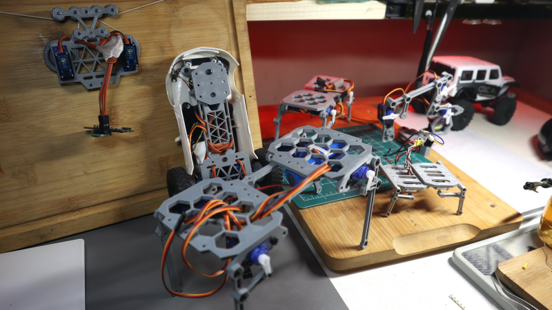
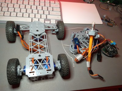
This Hackaday prize entry from [saul] is the beginning of a reconfigurable kit of 3D printed parts and servo motors for robotics learning. With just access to a printer, a few cheap-as-chips servo motors, an Arduino, and some nuts and bolts, you could be hacking together robot walkers within a few hours of starting!
Bolt Bots is very simple to understand, with all the mechanics and wiring out there in the breeze, but strictly for indoor use we reckon. If you want to add remote control to your application, then drop in one of the ubiquitous nRF24L01 boards and build yourself a copy of the remote control [saul] handily provides in this other project.
There really isn’t a great deal we can say about this, as it’s essentially a build kit with quite a few configuration options, and you just have to build with it and see what’s possible. We expect the number of parts to proliferate over time giving even more options. So far [saul] demonstrates a few flavors of ‘walkers’, a rudimentary ‘robot arm’, and even a hanging drawbot.
The bolt hardware can be found in this GitHub repo, and the remote control code in this second one.
Servo-based designs are sometimes sneered at due to their dubious accuracy and repeatability, but with a little of effort, this can be vastly improved upon. Also, multi-legged walkers need multiple servos and controllers to drive ’em. Or do they?
Many of us fell absolutely in love with Wall-E, the main character of a movie by the same name that came out in 2008. This tiny bot was so full of emotion and so adorable, we all wanted one in our lives. The youtube channel ProfessorBoots has put together this tiny version of Wall-E and […]
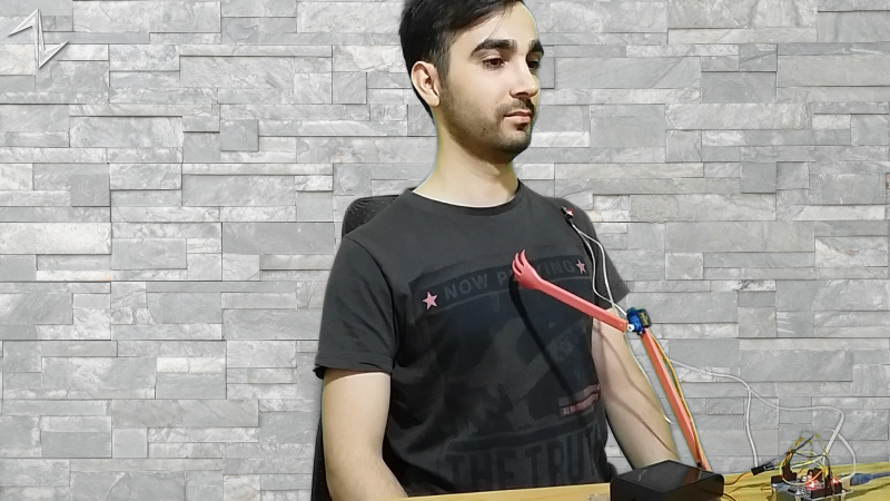
[Norbert Zare] has identified a problem many of us suffer from – chronically bad posture. Its very common to see computer users hunched forwards over a screen, which eventually will lead to back problems. He mentions that most posture correction devices are pretty boring, so the obvious solution to [Norbert] was to build a simple robot to give you a friendly nudge into the correct position.
This simple Arduino-based build uses the ubiquitous MPU-6050 which provides 3-axis acceleration and 3-axis gyro data all processed on-chip, so it can measure where you’re going, which way you are orientated and how fast you are rotating. This is communicated via the I2C bus, so hooking into an Arduino or Raspberry Pi is a simple affair. There are plenty of Open Source libraries to work with this very common device, which helps reduce the learning curve for those unfamiliar with programming a fairly complex device.
At the moment, he is mounting the sensor on his body, and hard-wiring it, so there’s already some scope for improvement there. The operating premise is simple, if the body angle is more than 55 degrees off vertical, move the servos and shove the body back in to the correct position.
[Greg06] started learning electronics the same way most of us did: buy a few kits, read a few tutorials, and try your hardest to put a few things together. Sound familiar? After a while, you noticed your skills started increasing, and your comfort level with different projects improved as well. Eventually, you try your hand at making your own custom projects and publishing your own tutorials.
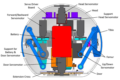
[Greg06’s] robot has a quadruped based, housed within a 3D printed spherical body. The legs are retractable and are actuated by tiny servo motors inside the body. [Greg06] even included an ultrasonic distance sensor for the obstacle avoidance mechanism. Honestly, if it weren’t for the ultrasonic distance sensor protruding from the spherical body, you might think that the entire robot was just a little Wiffle ball. This reminds us of another design we’ve seen before.
If that weren’t enough, the spherical head can rotate, widening the range of the ultrasonic distance sensor and obstacle avoidance mechanism. This is accomplished by attaching another servo motor to the head.
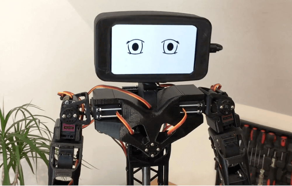
If you’d like to build your own vaguely humanoid robot, but don’t care about it getting around, then look no farther than Aster.
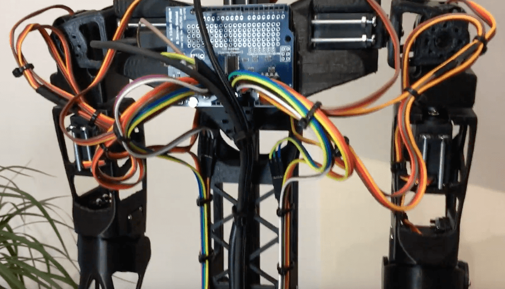
The 3D-printed bot is controlled by an Arduino Uno, with a servo shield to actuate its 16 servo motors. This enables it to move its arms quite dramatically as seen in the video below, along with its head. The legs also appear to be capable of movement, though not meant to walk, and is supported with a column in the middle of its structure.
Aster’s head display is made out of an old smartphone, and in the demo it shows its eyes as green geometric objects, an animated sketch, and then, somewhat shockingly, as different humans. Print files for the project are available here and the design is actually based on the more expensive Poppy Humanoid.
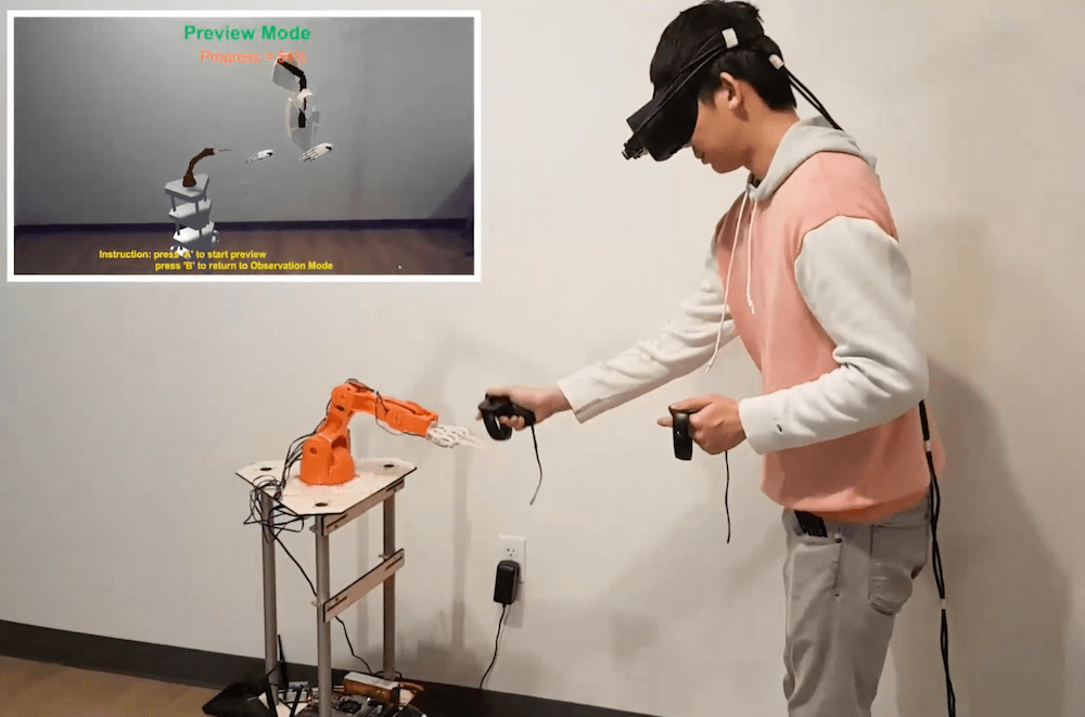
As robotics advance, the future could certainly involve humans and automated elements working together as a team. The question then becomes, how do you design such an interaction? A team of researchers from Purdue University attempt to provide a solution with their GhostAR system.
The setup records human movements for playback later in augmented reality, while a robotic partner is programmed to work around a “ghost” avatar. This enables a user to plan out how to collaborate with the robot and work out kinks before actually performing a task.
GhostAR’s hardware includes an Oculus Rift headset and IR LED tracking, along with actual robots used in development. Simulation hardware consists of a six-axis Tinkerkit Braccio robot, as well as an Arduino-controlled omni-wheel base that can mount either a robot an arm or a camera as needed.
With GhostX, whatever plan a user makes with the ghost form of the robot while wearing an augmented reality head mount is communicated to the real robot through a cloud connection – allowing both the user and robot to know what the other is doing as they perform a task. The system also allows the user plan a task directly in time and space and without any programming knowledge.
First, the user acts out the human part of the task to be completed with a robot. The system then captures the human’s behavior and displays it to the user as an avatar ghost, representing the user’s presence in time and space.
Using the human ghost as a time-space reference, the user programs the robot via its own ghost to match up with the human’s role. The user and robot then perform the task as their ghosts did.


 nRF24L01 boards and build yourself a copy of the remote control [saul] handily provides in