Posts with «ethernet» label

Tutorial – Ethernet Shields and Arduino

In this chapter we will introduce and examine the use of Ethernet networking with Arduino over local networks and the greater Internet.

It will be assumed that you have a basic understanding of computer networking, such as the knowledge of how to connect computers to a hub/router with RJ45 cables, what an IP and MAC address is, and so on. Furthermore, here is a good quick rundown about Ethernet.

Getting Started

You will need an Arduino Uno or compatible board with an Ethernet shield that uses the W5100 Ethernet controller IC (pretty much all of them):

Furthermore you will need to power the board via the external DC socket – the W5100 IC uses more current than the USB power can supply. A 9V 1.5A plug pack/wall wart will suffice.

Finally it does get hot – so be careful not to touch the W5100 after extended use. In case you’re not sure – this is the W5100 IC:

Once you have your Ethernet-enabled Arduino, and have the external power connected – it’s a good idea to check it all works. Open the Arduino IDE and select File > Examples > Ethernet > Webserver. This loads a simple sketch which will display data gathered from the analogue inputs on a web browser. However don’t upload it yet, it needs a slight modification.

You need to specify the IP address of the Ethernet shield – which is done inside the sketch. This is simple, go to the line:

IPAddress ip(192,168,1, 177);

And alter it to match your own setup. For example, in my home the router’s IP address is 10.1.1.1, the printer is 10.1.1.50 and all PCs are below …50. So I will set my shield IP to 10.1.1.77 by altering the line to:

IPAddress ip(10,1,1,77);

You also have the opportunity to change your MAC address. Each piece of networking equipment has a unique serial number to identify itself over a network, and this is normall hard-programmed into the equipments’ firmware. However with Arduino we can define the MAC address ourselves.

If you are running more than one Ethernet shield on your network, ensure they have different MAC addresses by altering the hexadecimal values in the line:

byte mac[] = { 0xDE, 0xAD, 0xBE, 0xEF, 0xFE, 0xED };

However if you only have one shield just leave it be. There may be the very, very, statistically rare chance of having a MAC address the same as your existing hardware, so that would be another time to change it.

Once you have made your alterations, save and upload the sketch. Now open a web browser and navigate to the IP address you entered in the sketch, and you should be presented with something similar to the following:

What’s happening? The Arduino has been programmed to offer a simple web page with the values measured by the analogue inputs. You can refresh the browser to get updated values.

At this point – please note that the Ethernet shields use digital pins 10~13, so you can’t use those for anything else. Some Arduino Ethernet shields may also have a microSD card socket, which also uses another digital pin – so check with the documentation to find out which one.

Nevertheless, now that we can see the Ethernet shield is working we can move on to something more useful. Let’s dissect the previous example in a simple way, and see how we can distribute and display more interesting data over the network. For reference, all of the Ethernet-related functions are handled by the Ethernet Arduino library. If you examine the previous sketch we just used, the section that will be of interest is:

 for (int analogChannel = 0; analogChannel < 6; analogChannel++) 
          {
            int sensorReading = analogRead(analogChannel);
            client.print("analog input ");
            client.print(analogChannel);
            client.print(" is ");
            client.print(sensorReading);
            client.println("<br />");       
          }
          client.println("</html>");

Hopefully this section of the sketch should be familiar – remember how we have used serial.print(); in the past when sending data to the serial monitor box? Well now we can do the same thing, but sending data from our Ethernet shield back to a web browser – on other words, a very basic type of web page.

However there is something you may or may not want to  learn in order to format the output in a readable format – HTML code. I am not a website developer (!) so will not delve into HTML too much.

However if you wish to serve up nicely formatted web pages with your Arduino and so on, here would be a good start. In the interests of simplicity, the following two functions will be the most useful:

client.print(" is ");

Client.print (); allows us to send text or data back to the web page. It works in the same way as serial.print(), so nothing new there. You can also specify the data type in the same way as with serial.print(). Naturally you can also use it to send data back as well. The other useful line is:

client.println("<br />");

which sends the HTML code back to the web browser telling it to start a new line. The part that actually causes the carriage return/new line is the <br /> which is an HTML code (or “tag”) for a new line. So if you are creating more elaborate web page displays, you can just insert other HTML tags in the client.print(); statement.

If you want to learn more about HTML commands, here’s a good tutorial site. Finally – note that the sketch will only send the data when it has been requested, that is when it has received a request from the web browser.

Accessing your Arduino over the Internet

So far – so good. But what if you want to access your Arduino from outside the local network?

You will need a static IP address – that is, the IP address your internet service provider assigns to your connection needs to stay the same. If you don’t have a static IP, as long as you leave your modem/router permanently swiched on your IP shouldn’t change. However that isn’t an optimal solution.

If your ISP cannot offer you a static IP at all, you can still move forward with the project by using an organisation that offers a Dynamic DNS. These organisations offer you your own static IP host name (e.g. mojo.monkeynuts.com) instead of a number, keep track of your changing IP address and linking it to the new host name. From what I can gather, your modem needs to support (have an in-built client for…) these DDNS services. As an example, two companies are No-IP andDynDNS.com. Please note that I haven’t used those two, they are just offered as examples.

Now, to find your IP address… usually this can be found by logging into your router’s administration page – it is usually 192.168.0.1 but could be different. Check with your supplier or ISP if they supplied the hardware. For this example, if I enter 10.1.1.1 in a web browser, and after entering my modem administration password, the following screen is presented:

What you are looking for is your WAN IP address, as you can see in the image above. To keep the pranksters away, I have blacked out some of my address.

The next thing to do is turn on port-forwarding. This tells the router where to redirect incoming requests from the outside world. When the modem receives such a request, we want to send that request to the port number of our Ethernet shield. Using the:

EthernetServer server(125);

function in our sketch has set the port number to 125. Each modem’s configuration screen will look different, but as an example here is one:

So you can see from the line number one in the image above, the inbound port numbers have been set to 125, and the IP address of the Ethernet shield has been set to 10.1.1.77 – the same as in the sketch.

After saving the settings, we’re all set. The external address of my Ethernet shield will be the WAN:125, so to access the Arduino I will type my WAN address with :125 at the end into the browser of the remote web device, which will contact the lonely Ethernet hardware back home.

Furthermore, you may need to alter your modem’s firewall settings, to allow the port 125 to be “open” to incoming requests. Please check your modem documentation for more information on how to do this.

Now from basically any Internet connected device in the free world, I can enter my WAN and port number into the URL field and receive the results. For example, from a phone when it is connected to the Internet via LTE mobile data:

So at this stage you can now display data on a simple web page created by your Arduino and access it from anywhere with unrestricted Internet access. With your previous Arduino knowledge you can now use data from sensors or other parts of a sketch and display it for retrieval.

Displaying sensor data on a web page

As an example of displaying sensor data on a web page, let’s use an inexpensive and popular temperature and humidity sensor – the DHT22. You will need to install the DHT22 Arduino library which can be found on this page. If this is your first time with the DHT22, experiment with the example sketch that’s included with the library so you understand how it works.

Connect the DHT22 with the data pin to Arduino D2, Vin to the 5V pin and GND to … GND.

Now for our sketch – to display the temperature and humidity on a web page. If you’re not up on HTML you can use online services such as this to generate the code, which you can then modify to use in the sketch.

In the example below, the temperature and humidity data from the DHT22 is served in a simple web page:

#include <SPI.h>
#include <Ethernet.h>

// for DHT22 sensor
#include "DHT.h"
#define DHTPIN 2
#define DHTTYPE DHT22

// Enter a MAC address and IP address for your controller below.
// The IP address will be dependent on your local network:
byte mac[] = {   0xDE, 0xAD, 0xBE, 0xEF, 0xFE, 0xED };
IPAddress ip(10,1,1,77);

// Initialize the Ethernet server library
// with the IP address and port you want to use 
// (port 80 is default for HTTP):
EthernetServer server(125);
DHT dht(DHTPIN, DHTTYPE);

void setup() 
{
  dht.begin();
 // Open serial communications and wait for port to open:
  Serial.begin(9600);
   while (!Serial) {
    ; // wait for serial port to connect. Needed for Leonardo only
  }
  // start the Ethernet connection and the server:
  Ethernet.begin(mac, ip);
  server.begin();
  Serial.print("server is at ");
  Serial.println(Ethernet.localIP());
}

void loop() 
{
  // listen for incoming clients
  EthernetClient client = server.available();
  if (client) {
    Serial.println("new client");
    // an http request ends with a blank line
    boolean currentLineIsBlank = true;
    while (client.connected()) {
      if (client.available()) {
        char c = client.read();
        Serial.write(c);
        // if you've gotten to the end of the line (received a newline
        // character) and the line is blank, the http request has ended,
        // so you can send a reply
        if (c == 'n' && currentLineIsBlank) 
        {
          // send a standard http response header
          client.println("HTTP/1.1 200 OK");
          client.println("Content-Type: text/html");
          client.println("Connection: close");  // the connection will be closed after completion of the response
	  client.println("Refresh: 30");  // refresh the page automatically every 30 sec
          client.println();
          client.println("<!DOCTYPE HTML>");
          client.println("<html>");

          // get data from DHT22 sensor
          float h = dht.readHumidity();
          float t = dht.readTemperature();
          Serial.println(t);
          Serial.println(h);

          // from here we can enter our own HTML code to create the web page
          client.print("<head><title>Office Weather</title></head><body><h1>Office Temperature</h1><p>Temperature - ");
          client.print(t);
          client.print(" degrees Celsius</p>");
          client.print("<p>Humidity - ");
          client.print(h);
          client.print(" percent</p>");
          client.print("<p><em>Page refreshes every 30 seconds.</em></p></body></html>");
          break;
        }
        if (c == 'n') {
          // you're starting a new line
          currentLineIsBlank = true;
        } 
        else if (c != 'r') {
          // you've gotten a character on the current line
          currentLineIsBlank = false;
        }
      }
    }
    // give the web browser time to receive the data
    delay(1);
    // close the connection:
    client.stop();
    Serial.println("client disonnected");
  }
}

It is a modification of the IDE’s webserver example sketch that we used previously – with a few modifications. First, the webpage will automatically refresh every 30 seconds – this parameter is set in the line:

client.println("Refresh: 30");  // refresh the page automatically every 30 sec

… and the custom HTML for our web page starts below the line:

// from here we can enter our own HTML code to create the web page

You can then simply insert the required HTML inside client.print() functions to create the layout you need.

Finally – here’s an example screen shot of the example sketch at work:

You now have the framework to create your own web pages that can display various data processed with your Arduino.

Conclusion

I hope you enjoyed making this or at least reading about it. If you find this sort of thing interesting, please consider ordering one or more of my books from amazon.

And as always, have fun and make something.

To keep up to date with new posts at tronixstuff.com, please subscribe to the mailing list in the box on the right, or follow us on twitter @tronixstuff.

Tronixstuff 09 Apr 08:09

Want to Learn Ethernet? Write Your Own Darn AVR Bootloader!

There’s a school of thought that says that to fully understand something, you need to build it yourself. OK, we’re not sure it’s really a school of thought, but that describes a heck of a lot of projects around these parts.

[Tim] aka [mitxela] wrote kiloboot partly because he wanted an Ethernet-capable Trivial File Transfer Protocol (TFTP) bootloader for an ATMega-powered project, and partly because he wanted to understand the Internet. See, if you’re writing a bootloader, you’ve got a limited amount of space and no device drivers or libraries of any kind to fall back on, so you’re going to learn your topic of choice the hard way.

[Tim]’s writeup of the odyssey of cramming so much into 1,000 bytes of code is fantastic. While explaining the Internet takes significantly more space than the Ethernet-capable bootloader itself, we’d wager that you’ll enjoy the compressed overview of UDP, IP, TFTP, and AVR bootloader wizardry as much as we did. And yes, at the end of the day, you’ve also got an Internet-flashable Arduino, which is just what the doctor ordered if you’re building a simple wired IoT device and you get tired of running down to the basement to upload new firmware.

Oh, and in case you hadn’t noticed, cramming an Ethernet bootloader into 1 kB is amazing.

Speaking of bootloaders, if you’re building an I2C slave device out of an ATtiny85¸ you’ll want to check out this bootloader that runs on the tiny chip.

RetroModem for the Commodore 64

Retrocomputers are fun, but ultimately limited in capability compared to modern hardware. One popular pursuit to rectify this is the connection of early home computers to the Internet. To that end, [que] built the Retromodem for the Commodore 64.

The build starts with a case from an Intel 14.4 modem. A little fast for the Commodore 64 era, but anachronism is charming when done tastefully. Inside is an Arduino with an ethernet module to handle the heavy lifting of carrying packets to the outside world.  [que] took the time to wire up status LEDs for the proper vintage look, which really adds something to the project. They switch on and off to indicate the various settings on the modem – it’s great to see in the video below the break the “HS” LED light up when the baud rate is changed to a higher speed.

The project implements most of the Hayes command set, so you can interface with it over a serial terminal just like it’s 1983. [que] doesn’t go into too many details of how it’s all put together, but for the experienced code warrior it’s a project that could be whipped up in a weekend or two. For a more modern take, perhaps you’d like to hook your C64 up over Wifi instead?


Filed under: classic hacks, computer hacks

Get Arduino Data over the internet using jQuery and AJAX

Description

Have you ever wanted to transmit Arduino data over the internet?

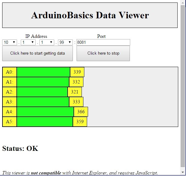
In this tutorial, we will design a web page that will retrieve Analog readings from the Arduino's Analog Pins and display them on a bar chart within the web page.

The web page will use jQuery and AJAX to request the data from the Arduino Web Server, allowing us to update the bar chart dynamically, without having to refresh the entire web page. The Arduino Web Server will send the Analog readings to the web page in JSON format where it will be processed and displayed accordingly.

In this tutorial, I will not have anything connected to the Arduino's Analog pins, which means the data retrieved will be that of randomly floating analog pins. Feel free to connect a potentiometer, temperature sensor or any other analog sensor to these pins if you want to create a more "useful" project.

The main aim here was to show you how to transmit the data in JSON format, and to update only a portion of the web page using asynchronous communication (using AJAX), to improve the performance of data retrieval and visualisation.


Arduino Libraries and IDE

To program the Arduino you will need to download the Arduino IDE, and install the WIZnet Ethernet Library. The Arduino IDE version used in this tutorial was version 1.6.4.
You may want to read the WIZnet wiki information for each WIZnet shield before use.


ARDUINO CODE:

Full description of the Arduino code is included in the YouTube video above. Once you have set up your Arduino Web Server, you should be able to ping it. Look at this website, if you don't know how to use the windows ping feature.


Getting the Arduino Board onto the internet:

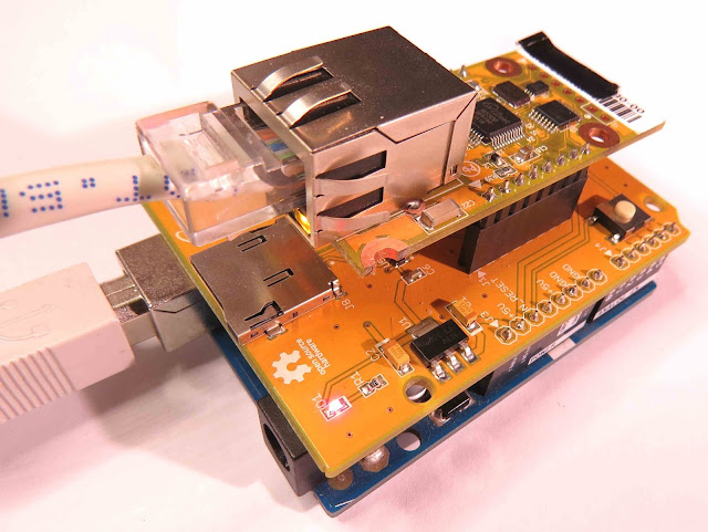
There isn't anything really to hook up for this project. You just have to align the pins for each board and stack them. You can power the Arduino via the USB cable. This will also be useful for debugging and printing to the Serial monitor. An ethernet cable needs to connect the WIZ550io board's ethernet port to your internet/network router

  • The WIZ550io board goes on the top

  • The ioShield-A is in the middle

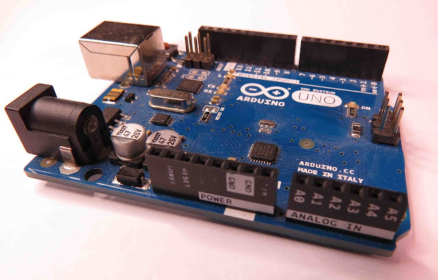
  • The Arduino UNO is on the bottom

  • This is what it looks like when they are stacked together

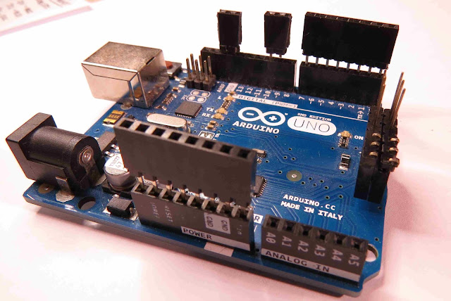
  • If you want to gain easy access to the Analog or digital pins without de-soldering the ioShield-A, you can introduce some female headers like this:

  • Please note that the ioShield-A utilises a number of pins on the Arduino UNO - including: D2, D4, D7, D10, GND, and IOREF, RESET, 5V, GND, GND and ICSP pins
  • All Analog pins are available for use


Set the Arduino Web Server on your local network

You can test this project on your local network. You just have to choose an available IP address and PORT within your router's IP range. If you don't know your local IP address range - you can have a look at this site to give you a helping hand.


Set the Arduino Web Server to be accessed from anywhere in the world

If you want to access your Arduino from anywhere in the world, you need to set up Port Forwarding on your internet network router. The following useful guides will hopefully get you on the right track, if you have never set up Port forwarding.


In my case, I programmed the Arduino UNO Web Server to take the following ip address on my internal network: 10.1.1.99

I programmed the Arduino Web Server to listen for Web Browsers on port 8081.
So if I wanted to connect to the Arduino Web Server through my home network, I just had to type in this web address into my web browser: http://10.1.1.99:8081

If you plan to connect to the Arduino using port 80 (which is the default port for web browsers), you can just type the IP address without specifying the port (eg. http://10.1.1.99/ )

The web browser should display the Arduino data in JSON format (the YouTube video above will show you what that looks like).

Once I knew I could connect to the Arduino in my internal network, I then set up port forwarding on my router so that I could type in my external IP address and special port to tunnel my way into my Arduino Web Server on my internal network. This is what I had to do on my router, but you may need to do something different.

  1. My first step was to find out my public/external IP address by typing "what is my IP address" into google. If you want to know your external IP address click here.
  2. I then typed my router's ip address into a web browser, and logged into my router.
  3. I went to the advanced settings tab
  4. Selected "Port Forwarding" from the side menu
  5. Filled out all of the details on the first line of the Ports list
    • Enable box = ticked
    • Description = Arduino
    • WAN interface = pppoe_atm0/ppp0
    • Inbound port = 8082
    • Type = TCP
    • Private IP address = 10.1.1.99
    • Private port = 8081
  6. Saved the settings

Now that I had port forwarding enabled, I could type the ip address (that I obtained in step 1) into my browser and specified port 8082 (instead of 8081) - eg. http://190.11.70.253:8082/

And now I can access my Arduino Web server from anywhere in the world. I can even access it from my smart phone. Once again, this will only return the Analog data in JSON format.


The Web Page GUI

The Arduino is now on the internet, so there are two options. You can either

Instructions on how to use these web pages, are listed below the HTML code.


To retrieve data from your Arduino Web Server, please make sure that it is connected and visible from outside of you local network. You will need to have port forwarding enabled. Information on port forwarding is described above.

  1. Find what your external IP address is.
  2. Enter this address using the IP address drop-down boxes within the "ArduinoBasics Webserver Data viewer" web page
  3. Enter the port forwarding port number (eg. 8082) into the box labelled "Port"
  4. Then click on the "Click here to start getting data" button - you should start to see the bar charts moving and status should be OK
  5. If the bar charts do not move, and the status message says "Failed to get DATA!!" - then the web page was unable to connect to the Arduino for some reason.


Troubleshooting

  • You may want to type in the web address into your web browser, to make sure that data is being retrieved.
  • You can also open the Serial monitor in the Arduino IDE to make sure that an IP address is being displayed
  • Ensure that you have enabled the port forwarding option on your router
  • Have a look at Developer Tools within Google Chrome to help diagnose web page related issues.
  • The web page will not work properly if you use Internet Explorer or if you have javascript disabled within your browser.

Concluding comments

This tutorial showed you how to connect to your Arduino UNO over the internet, and retrieve data in JSON format using jQuery and AJAX. The web page can be modified to suit your own needs, plus it would be more useful if the Arduino was actually monitoring something, rather than logging data from floating pins. It would also be useful if the Arduino could be controlled to blink an LED, or to turn a motor... but I will leave that project for another day. I hope you enjoyed this tutorial - if it helped you in any way, please consider donating a small "tip" into my money jar. Thank you.


If you like this page, please do me a favour and show your appreciation :

 
Visit my ArduinoBasics Google + page.
Follow me on Twitter by looking for ScottC @ArduinoBasics.
I can also be found on Pinterest and Instagram.
Have a look at my videos on my YouTube channel.


This project would not have been possible without WIZnet's collaborative effort.
Please visit their site for more cool Ethernet products.


However, if you do not have a google profile...
Feel free to share this page with your friends in any way you see fit.

Get Arduino Data over the internet using jQuery and AJAX


Description


Have you ever wanted to transmit Arduino data over the internet?

In this tutorial, we will design a web page that will retrieve Analog readings from the Arduino's Analog Pins and display them on a bar chart within the web page.

The web page will use jQuery and AJAX to request the data from the Arduino Web Server, allowing us to update the bar chart dynamically, without having to refresh the entire web page. The Arduino Web Server will send the Analog readings to the web page in JSON format where it will be processed and displayed accordingly.

In this tutorial, I will not have anything connected to the Arduino's Analog pins, which means the data retrieved will be that of randomly floating analog pins. Feel free to connect a potentiometer, temperature sensor or any other analog sensor to these pins if you want to create a more "useful" project.

The main aim here was to show you how to transmit the data in JSON format, and to update only a portion of the web page using asynchronous communication (using AJAX), to improve the performance of data retrieval and visualisation.


Parts Required:


Please note: The WIZnet ioShield-A ver1.1 actually comes with the WIZ550io board. So if you buy the ioShield-A, you will receive both boards. I have provided the link to the WIZ550io shield because you can buy that shield on its own. Regardless, you will need to use both boards for this tutorial.


Arduino Libraries and IDE


To program the Arduino you will need to download the Arduino IDE, and install the WIZnet Ethernet Library. The Arduino IDE version used in this tutorial was version 1.6.4.
You may want to read the WIZnet wiki information for each WIZnet shield before use.


ARDUINO CODE:


Full description of the Arduino code is included in the YouTube video above. Once you have set up your Arduino Web Server, you should be able to ping it. Look at this website, if you don't know how to use the windows ping feature.


Getting the Arduino Board onto the internet:


There isn't anything really to hook up for this project. You just have to align the pins for each board and stack them. You can power the Arduino via the USB cable. This will also be useful for debugging and printing to the Serial monitor. An ethernet cable needs to connect the WIZ550io board's ethernet port to your internet/network router

  • The WIZ550io board goes on the top

  • The ioShield-A is in the middle

  • The Arduino UNO is on the bottom

  • This is what it looks like when they are stacked together

  • If you want to gain easy access to the Analog or digital pins without de-soldering the ioShield-A, you can introduce some female headers like this:

  • Please note that the ioShield-A utilises a number of pins on the Arduino UNO - including: D2, D4, D7, D10, GND, and IOREF, RESET, 5V, GND, GND and ICSP pins
  • All Analog pins are available for use


Set the Arduino Web Server on your local network


You can test this project on your local network. You just have to choose an available IP address and PORT within your router's IP range. If you don't know your local IP address range - you can have a look at this site to give you a helping hand.


Set the Arduino Web Server to be accessed from anywhere in the world


If you want to access your Arduino from anywhere in the world, you need to set up Port Forwarding on your internet network router. The following useful guides will hopefully get you on the right track, if you have never set up Port forwarding.


In my case, I programmed the Arduino UNO Web Server to take the following ip address on my internal network: 10.1.1.99

I programmed the Arduino Web Server to listen for Web Browsers on port 8081.
So if I wanted to connect to the Arduino Web Server through my home network, I just had to type in this web address into my web browser: http://10.1.1.99:8081

If you plan to connect to the Arduino using port 80 (which is the default port for web browsers), you can just type the IP address without specifying the port (eg. http://10.1.1.99/ )

The web browser should display the Arduino data in JSON format (the YouTube video above will show you what that looks like).

Once I knew I could connect to the Arduino in my internal network, I then set up port forwarding on my router so that I could type in my external IP address and special port to tunnel my way into my Arduino Web Server on my internal network. This is what I had to do on my router, but you may need to do something different.

  1. My first step was to find out my public/external IP address by typing "what is my IP address" into google. If you want to know your external IP address click here.
  2. I then typed my router's ip address into a web browser, and logged into my router.
  3. I went to the advanced settings tab
  4. Selected "Port Forwarding" from the side menu
  5. Filled out all of the details on the first line of the Ports list
    • Enable box = ticked
    • Description = Arduino
    • WAN interface = pppoe_atm0/ppp0
    • Inbound port = 8082
    • Type = TCP
    • Private IP address = 10.1.1.99
    • Private port = 8081
  6. Saved the settings

Now that I had port forwarding enabled, I could type the ip address (that I obtained in step 1) into my browser and specified port 8082 (instead of 8081) - eg. http://190.11.70.253:8082/

And now I can access my Arduino Web server from anywhere in the world. I can even access it from my smart phone. Once again, this will only return the Analog data in JSON format.


The Web Page GUI


The Arduino is now on the internet, so there are two options. You can either


Instructions on how to use these web pages, are listed below the HTML code.


To retrieve data from your Arduino Web Server, please make sure that it is connected and visible from outside of you local network. You will need to have port forwarding enabled. Information on port forwarding is described above.
  1. Find what your external IP address is.
  2. Enter this address using the IP address drop-down boxes within the "ArduinoBasics Webserver Data viewer" web page
  3. Enter the port forwarding port number (eg. 8082) into the box labelled "Port"
  4. Then click on the "Click here to start getting data" button - you should start to see the bar charts moving and status should be OK
  5. If the bar charts do not move, and the status message says "Failed to get DATA!!" - then the web page was unable to connect to the Arduino for some reason.


Troubleshooting

  • You may want to type in the web address into your web browser, to make sure that data is being retrieved.
  • You can also open the Serial monitor in the Arduino IDE to make sure that an IP address is being displayed
  • Ensure that you have enabled the port forwarding option on your router
  • Have a look at Developer Tools within Google Chrome to help diagnose web page related issues.
  • The web page will not work properly if you use Internet Explorer or if you have javascript disabled within your browser.


Concluding comments


This tutorial showed you how to connect to your Arduino UNO over the internet, and retrieve data in JSON format using jQuery and AJAX. The web page can be modified to suit your own needs, plus it would be more useful if the Arduino was actually monitoring something, rather than logging data from floating pins. It would also be useful if the Arduino could be controlled to blink an LED, or to turn a motor... but I will leave that project for another day. Thank you.

If you like this page, please do me a favour and show your appreciation :

 
Visit my ArduinoBasics Google + page.
Follow me on Twitter by looking for ScottC @ArduinoBasics.
I can also be found on Pinterest and Instagram.
Have a look at my videos on my YouTube channel.
             
This project would not have been possible without WIZnet's collaborative effort.
Please visit their site for more cool Ethernet products.


However, if you do not have a google profile...
Feel free to share this page with your friends in any way you see fit.

Bread Online is a Bread Maker for the Internet of Things

An engineering student at the University of Western Macedonia has just added another appliance to the ever-growing list of Internet enabled things. [Panagiotis] decided to modify an off-the-shelf bread maker to enable remote control via the Internet.

[Panagiotis] had to remove pretty much all of the original control circuitry for this device. The original controller was replaced with an Arduino Uno R3 and an Ethernet shield. The temperature sensor also needed to be replaced, since [Panagiotis] could not find any official documentation describing the specifications of the original. Luckily, the heating element and mixer motor were able to be re-used.

A few holes were drilled into the case to make room for the Ethernet connector as well as a USB connector. Two relays were used to allow the Arduino to switch the heating element and mixer motor on and off. The front panel of the bread maker came with a simple LCD screen and a few control buttons. Rather than let those go to waste, they were also wired into the Arduino.

The Arduino bread maker can be controlled via a web site that runs on a separate server. The website is coded with PHP and runs on Apache. It has a simple interface that allows the user to specify several settings including how much bread is being cooked as well as the desired darkness of the bread. The user can then schedule the bread maker to start. Bread Online also comes with an “offline” mode so that it can be used locally without the need for a computer or web browser. Be sure to check out the video demonstration below.

[Thanks Minas]


Filed under: Arduino Hacks, cooking hacks

An Arduino Device that Monitors Your External IP Address

[Bayres’] dad setup a webcam as a surveillance camera for a remote property. The only problem was that the only stable Internet connection they could get at this property was DSL. This meant that the external IP address of the webcam would change somewhat often; the needed a way to keep track of the external IP address whenever it changed. That’s when [Bayres] built a solution using Arduino and an Ethernet shield.

The main function of this device is to monitor the public IP address and report any changes. This is accomplished by first making a request to checkip.dyndns.org. This website simply reports your current public IP address. [Bayres] uses an Arduino library called Textfinder in order to search through the returned string and identify the IP address.

From there, the program compares this current value to the previous one. If there is any change, the program uses the Sendmail() function to reach out to an SMTP server and send an e-mail alert to [Beyres’] dad. The system also includes a small LCD. The Arduino outputs the current IP address to this display, making it easy to check up on the connection. The LCD is driven by 74HC595 shift register in order to conserve pins on the Arduino.

The system is also designed with a pretty slick setup interface. When it is booted, the user can enter a configuration menu via a Serial terminal. This setup menu allows the user to configure options such as SMTP server, email address, etc. These variables are then edited and can be committed to EEPROM as a more permanent storage solution. Whenever the system is booted, these values are read back out of the EEPROM and returned to their appropriate variables. This means you can reconfigure the device on the fly without having to edit the source code and re-upload.


Filed under: Arduino Hacks

Weather Reporter - Temboo, Ethernet and Arduino


Arduino is well known for the large variety of sensors / modules that can be connected. It is quite easy to hook up a temperature or humidity sensor to get instant feedback about the surrounding environmental conditions. However, sometimes you do not have a temperature sensor. Sometimes you have a sensor, but would like to know the temperature in other cities ! Or you would like to know what the temperature will be tomorrow?

Well now you can !!

All you need is a Temboo account, an internet connection and the following components:

Parts Required


Project Description


An Arduino UNO (and Ethernet Shield) queries Yahoo using a Temboo account, and retrieves weather information. The data is filtered and processed, and then passed on to another Arduino UNO to be displayed on a TFT LCD module. Two Arduino UNOs are used because the Ethernet library and the UTFT library are both memory hungry, and together consume more memory than one Arduino UNO can handle. Yes - I could have used a different board such as the Arduino MEGA, but where is the fun in that ?? This project will teach you many things:
  • How to use an Ethernet Shield with a Temboo account to retrieve internet data
  • How to use a TFT LCD module (ITDB02-1.8SP)
  • How to reduce memory consumption when using the UTFT library
  • How to power two Arduinos with a single USB cable
  • How to transmit data from one Arduino to another (via jumper wires)
All of this and a whole lot more !!


Video

Have a look at the following video to see the project in action.


You will need to create a Temboo account to run this project:

Temboo Account Creation

Step 1:

Visit the Temboo website : https://www.temboo.com/ Create an account by entering a valid email address. Then click on the Sign Up button.


Step 2:

Verify your email address by clicking on the link provided in the email sent by Temboo.


Step 3:

You will be directed to the account setup page: Create an Account Name, and Password for future access to your Temboo Account Check the terms of service and if you agree, then tick the box Press the Go! button


Step 4:

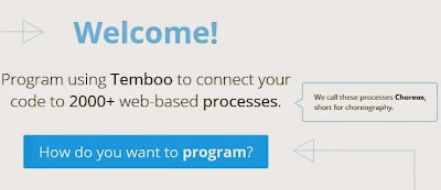
You will then encounter the "Welcome!" screen:


Step 5:

Navigate to the top right of the screen and select the LIBRARY tab


Step 6:

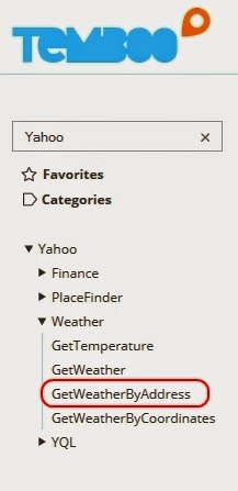
On the left hand side you will see a list of choreos. Type Yahoo into the search box on the top left of the screen. Navigate to the GetWeatherByAddress Choreo by clicking on...     Yahoo _ Weather _ GetWeatherByAddress


Step 7:

Turn the IoT Mode to ON (in the top right of screen)


Step 8:

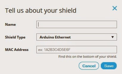
What's your platform / device? : Arduino How is it connected? : Arduino Ethernet   The following popup box will appear:


Step 9:

Name: EthernetShield - you can choose any name. Letters and numbers only. No spaces. Shield Type: Arduino Ethernet MAC Address : You can normally find the MAC address of the Ethernet shield on the underside. Enter the MAC address without the hyphens. Then click SAVE.


Step 10:

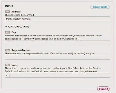
Move to the INPUT section. Enter the Address of the place you want the Temperature for. Address = Perth, Western Australia Expand the Optional INPUT for extra functionality Units = c - If you want the temperature in Celcius.


Step 11:

This will automatically generate some Arduino CODE and a HEADER FILE. Don't worry about the Arduino code for now... because I will provide that for you. However, you will need the automatically generated HEADER file. I will show you what to do with that soon. So don't lose it !'


Temboo Library Install

The Temboo library will need to be installed before you copy the Arduino code in the sections below. To install the Temboo library into your Arduino IDE, please follow the link to their instructions:   Installing the Temboo Arduino Library


UTFT Library Install

Download the UTFT library from this site: http://www.henningkarlsen.com/electronics/library.php?id=51 Once downloaded and extracted. Go into the UTFT folder and look for the memorysaver.h file. Open this file in a text editor, and "uncomment" all of the TFT modules that are not relevant to this project. I disabled all of the TFT modules except the last 3 (which made reference to ST7735) - see picture below. The TFT module we are using in this project is the ITDB02-1.8SP from ITEAD Studio. Save the memorysaver.h file, and then IMPORT the library into the Arduino IDE as per the normal library import procedure.   If you do not modify the memorysaver.h file, the Arduino SLAVE sketch will not compile.


Arduino Code (MASTER)

  This project uses 2 Arduino UNOs. One will be the Master, and one will be the Slave. The following code is for the Arduino MASTER.   Open up the Arduino IDE. (I am using Arduino IDE version 1.6) Paste the following code into the Arduino IDE code window.   PLEASE NOTE: You may need to change some of the lines to accomodate your INPUTS from step 10. Have a look around line 36 and 37.  
  1
2
3
4
5
6
7
8
9
10
11
12
13
14
15
16
17
18
19
20
21
22
23
24
25
26
27
28
29
30
31
32
33
34
35
36
37
38
39
40
41
42
43
44
45
46
47
48
49
50
51
52
53
54
55
56
57
58
59
60
61
62
63
64
65
66
67
68
69
70
71
72
73
74
75
76
77
78
79
80
81
82
83
84
85
86
87
88
89
90
91
92
93
94
95
96
97
98
99
100
101
102
103
104
105
106
107
108
109
110
111
112
113
114
115
116
117
118
119
120
121
122
123
124
125
126
127
128
129
130
131
132
132
133
134
135
136
137
138
139
140
141
142
143
144
145
146
147
148
149
150
151
152
153
154
155
156
157
158
159
160
161
162
163
164
165
166
167
168
169
170
171
172
173
174
175
176
177
178
179
180
181
182
183
184
185
186
187


/* ===============================================================================
      Project: Weather Reporter: Temboo, Ethernet, Arduino
        Title: ARDUINO MASTER: Get temperature from Yahoo using Temboo
       Author: Scott C
      Created: 27th February 2015
  Arduino IDE: 1.6.0
      Website: http://arduinobasics.blogspot.com/p/arduino-basics-projects-page.html
  Description: The following sketch was designed for the Arduino MASTER device. 
               It will retrieve temperature/weather information from Yahoo using your
               Temboo account (https://www.temboo.com/), which will then be sent to the
               Arduino Slave device to be displayed on a TFT LCD module.
               
   Libraries : Ethernet Library (that comes with Arduino IDE)
               Temboo Arduino Library - https://www.temboo.com/sdk/arduino
               
   Temboo Library installation instructions for Arduino: 
               https://www.temboo.com/arduino/others/library-installation

  You will also need to copy your Temboo Account information into a new tab and call it TembooAccount.h.
  Please follow the instructions on the ArduinoBasics blog for more information.
---------------------------------------------------------------------------------- */

#include <SPI.h>
#include <Dhcp.h>
#include <Dns.h>
#include <Ethernet.h>
#include <EthernetClient.h>
#include <Temboo.h>
#include "TembooAccount.h" // Contains Temboo account information - in a new tab.
#include <Wire.h>

byte ethernetMACAddress[] = ETHERNET_SHIELD_MAC; //ETHERNET_SHIELD_MAC variable located in TembooAccount.h
EthernetClient client;

String Address = "Perth, Western Australia"; // Find temperature for Perth, Western Australia
String Units = "c"; // Display the temperature in degrees Celcius

String ForeCastDay[7]; //String Array to hold the day of the week
String ForeCastTemp[7]; //String Array to hold the temperature for that day of week.

int counter1=0; //Counters used in FOR-LOOPS.
int counter2=0;

boolean downloadTemp = true; // A boolean variable which controls when to query Yahoo for Temperature information.


void setup() {
  Wire.begin(); // join i2c bus : Used to communicate to the Arduino SLAVE device.
 
  // Ethernet shield must initialise properly to continue with sketch.
  if (Ethernet.begin(ethernetMACAddress) == 0) {
    while(true);
  }
  
  //Provide some time to get both Arduino's ready for Temperature Query.
    delay(2000);
}


void loop() {
  if (downloadTemp) {
    downloadTemp=false; //Stop Arduino from Querying Temboo repeatedly
    getTemperature();       //Retrieve Temperature data from Yahoo
    transmitResults();      //Transmit the temperature results to the Slave Arduino
  }
}


/* This function will Query Yahoo for Temperature information (using a Temboo account) */

void getTemperature(){
    TembooChoreo GetWeatherByAddressChoreo(client);

    // Invoke the Temboo client
    GetWeatherByAddressChoreo.begin();

    // Set Temboo account credentials
    GetWeatherByAddressChoreo.setAccountName(TEMBOO_ACCOUNT); //TEMBOO_ACCOUNT variable can be found in TembooAccount.h file or tab
    GetWeatherByAddressChoreo.setAppKeyName(TEMBOO_APP_KEY_NAME); //TEMBOO_APP_KEY_NAME variable can be found in TembooAccount.h file or tab
    GetWeatherByAddressChoreo.setAppKey(TEMBOO_APP_KEY); //TEMBOO_APP_KEY variable can be found in TembooAccount.h file or tab

    // Set Choreo inputs
    GetWeatherByAddressChoreo.addInput("Units", Units); // Set the Units to Celcius
    GetWeatherByAddressChoreo.addInput("Address", Address); // Set the Weather Location to Perth, Western Australia

    // Identify the Choreo to run
    GetWeatherByAddressChoreo.setChoreo("/Library/Yahoo/Weather/GetWeatherByAddress");

    // This output filter will extract the expected temperature for today
    GetWeatherByAddressChoreo.addOutputFilter("Temperature", "/rss/channel/item/yweather:condition/@temp", "Response");
    
    // These output filters will extract the forecasted temperatures (we need to know the day and temperature for that day)
    GetWeatherByAddressChoreo.addOutputFilter("ForeCastDay", "/rss/channel/item/yweather:forecast/@day", "Response");
    GetWeatherByAddressChoreo.addOutputFilter("ForeCastHigh", "/rss/channel/item/yweather:forecast/@high", "Response");

    // Run the Choreo;
    GetWeatherByAddressChoreo.run();

    //Reset our counters before proceeding
    counter1 = 0;
    counter2 = 0;
    
    while(GetWeatherByAddressChoreo.available()) {
      // This will get the first part of the output
      String name = GetWeatherByAddressChoreo.readStringUntil('\x1F');
      name.trim(); // get rid of newlines

      // This will get the second part of the output
      String data = GetWeatherByAddressChoreo.readStringUntil('\x1E');
      data.trim(); // get rid of newlines

      //Fill the String Arrays with the Temperature/Weather data
      if (name == "Temperature") {
        ForeCastDay[counter1] = "Today";
        ForeCastTemp[counter2] = data;
        counter1++;
        counter2++;
      }
      
      if(name=="ForeCastDay"){
        ForeCastDay[counter1] = data;
        counter1++;
      }
      
      if(name=="ForeCastHigh"){
        ForeCastTemp[counter2] = data;
        counter2++;
      }
    }
  
    //Close the connection to Temboo website
    GetWeatherByAddressChoreo.close();
  }


  /* This function is used to transmit the temperature data to the Slave Arduino */
  
  void transmitResults(){
    char tempData[10];
    int tempStringLength = 0;
    
    //Modify the current temp to "Now"
    ForeCastDay[0] = "Now";
    
    //Send * to Slave Arduino to prepare for Temperature Transmission
    Wire.beginTransmission(4); // Transmit to device #4 (Slave Arduino)
    Wire.write("*");
    delay(500);
    Wire.endTransmission();
    delay(500);
    
    //Send the temperatures on the Slave Arduino to be displayed on the TFT module.
    for (int j=0; j<20; j++){
      for (int i=0; i<6; i++){
        memset(tempData,0,sizeof(tempData));   //Clear the character array
        String tempString = String(ForeCastDay[i] + "," + ForeCastTemp[i] + ".");
        tempStringLength = tempString.length();
        tempString.toCharArray(tempData, tempStringLength+1);
        Wire.beginTransmission(4); // Transmit to device #4 (Slave Arduino)
        Wire.write(tempData);
        delay(1000);
        Wire.endTransmission();
        delay(4000);
      }
    }
    
    /* ----------------------------------------------------------------------
    // You can use this to send temperature results to the Serial Monitor.
    // However, you will need a Serial.begin(9600); statement in setup().
    
    Serial.println("The Current Temperature is " + ForeCastTemp[5] + " C");
    Serial.println();
    Serial.println("The Expected Temperature for");
    for (int i=0; i<5; i++){
      Serial.println(ForeCastDay[i] + " : " + ForeCastTemp[i] + " C");
    }
    ---------------------------------------------------------- */
  }


Select "New Tab" from the drop-down menu on the top right of the IDE. Name the file: TembooAccount.h

Paste the contents of the HEADER file from the Temboo webpage (Step 11 above) into the TembooAccount.h tab. If you do not have the TembooAccount.h tab with the contents of this HEADER file next to your Arduino Master sketch, then it will NOT work.  
Make sure to SAVE the Arduino Sketch and upload the code to the Arduino (MASTER)


Arduino Code (SLAVE)

  This project uses 2 Arduino UNOs. One will be the Master, and one will be the Slave. The following code is for the Arduino SLAVE.   Make sure to disconnect the Arduino MASTER from your computer, and keep it to one side. Connect the Arduino SLAVE to your computer, and upload the following code to it. Make sure to create a new sketch for this code (File _ New).  
  1
2
3
4
5
6
7
8
9
10
11
12
13
14
15
16
17
18
19
20
21
22
23
24
25
26
27
28
29
30
31
32
33
34
35
36
37
38
39
40
41
42
43
44
45
46
47
48
49
50
51
52
53
54
55
56
57
58
59
60
61
62
63
64
65
66
67
68
69
70
71
72
73
74
75
76
77
78
79
80
81
82
83
84
85
86
87
88
89
90
91
92
93
94
95
96
97
98
99
100
101
102
103
104
105
106
107
108
109
110
111
112
113
114
115
116
117
118
119
120
121
122
123
124
125
126
127
128
129
130
131
132
133
134
135
136
137
138
139
140
141
142
143
144
145
146
147
148
149
150
151
152
153
154
155
156
157
158
159
160
161
162
163
164
165
166
167
168
169
170
171
172
173
174
175
176
177
178
179
180
181
182
183
184
185
186
187
188
189
190
191
192
193
194
195
196
197


/* ===============================================================================
      Project: Weather Reporter: Temboo, Ethernet, Arduino
        Title: ARDUINO SLAVE: Display temperature on TFT LCD Module
       Author: Scott C
      Created: 27th February 2015
  Arduino IDE: 1.6.0
      Website: http://arduinobasics.blogspot.com/p/arduino-basics-projects-page.html
  Description: The following sketch was designed for the Arduino SLAVE device. 
               It will receive temperature information from the Arduino MASTER
               and then display this information on the ITDB02-1.8SP TFT LCD 
               Module. Please read the important notes below.

----------------------------------------------------------------------------------
NOTES:
This sketch makes use of the UTFT.h library from : 
http://www.henningkarlsen.com/electronics/library.php?id=51
Please note: You will need to modify the memorysaver.h file in the UTFT folder 
with a text editor to disable any unused TFT modules. This will save memory, 
and allow you to run this sketch on an Arduino UNO. I disabled all TFT modules in
that file except the last 3 (which made reference to ST7735).
I used a ITDB02-1.8SP TFT LCD Module from ITEAD Studio.
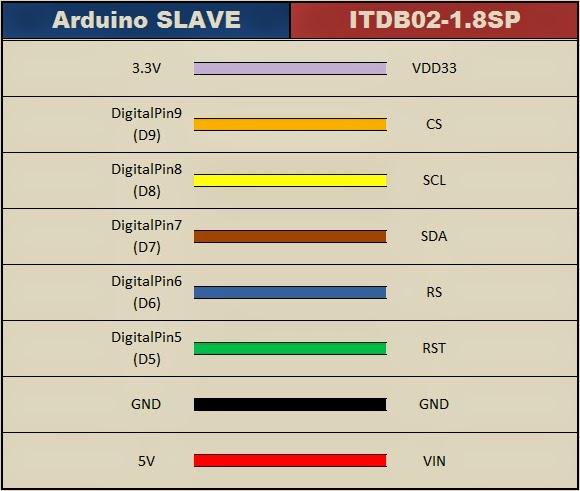
PinOut:

Arduino SLAVE      ITDB02-1.8SP TFT
         3.3V ---- VDD33
 Digital9 (D9)---- CS
 Digital8 (D8)---- SCL
 Digital7 (D7)---- SDA
 Digital6 (D6)---- RS
 Digital5 (D5)---- RST
          GND ---- GND
           5V ---- VIN

Usage: UTFT myGLCD(<model code>, SDA, SCL, CS, RST, RS);
Example: UTFT myGLCD(ITDB18SP,7,8,9,5,6);

-----------------------------------------------------------------------------------
This sketch also makes use of the Wire.h library. 
The Wire.h library comes with the Arduino IDE.
This enables communication between Arduino Master and Arduino Slave.
PinOut:

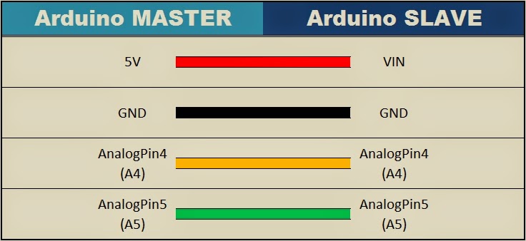
Arduino MASTER      Arduino SLAVE
   Analog4(A4) ---- Analog4 (A4) 
   Analog5(A5) ---- Analog5 (A5) 
           GND ---- GND

-----------------------------------------------------------------------------------
The Arduino Slave is powered by the Arduino Master:
PinOut:

Arduino MASTER      Arduino SLAVE
            5V ---- VIN

==================================================================================
*/

#include <UTFT.h>
#include <Wire.h>

//Declare all of the fonts
extern uint8_t SmallFont[];
extern uint8_t BigFont[];
extern uint8_t SevenSegNumFont[];

// Usage: UTFT myGLCD(<model code>, SDA, SCL, CS, RST, RS);
UTFT myGLCD(ITDB18SP,7,8,9,5,6);

boolean tempDisplay = false; //Helps with processing the data from the Arduino MASTER
boolean readTemp = false; //Helps to differentiate the day from the temperature values
String dayOfWeek=""; //Variable used to hold the Day of the Week
String tempReading=""; //Variable used to hold the Temperature for that day

String Units = "'C "; //Display Temperature in Celcius
String Address = "Perth, WA"; //Address to show at top of Display


void setup(){
  // Initialise the TFT LCD
  myGLCD.InitLCD();
  initialiseLCD();
  delay(5000);
  
  //Setup the Serial communication between the Arduino MASTER and SLAVE
  Wire.begin(4); // join i2c bus with address #4
  Wire.onReceive(receiveEvent); // register event
}


void loop(){
  delay(50);
}


/*
  This function initialises the TFT LCD, and draws the initial screen.
*/
void initialiseLCD(){
  //Clear the screen
  myGLCD.clrScr();
  
  //Draw the borders (top and bottom)
  myGLCD.setColor(25, 35, 4);
  myGLCD.fillRect(0, 0, 159, 13);
  myGLCD.fillRect(0, 114, 159, 127);
  myGLCD.drawLine(0,18,159,18);
  myGLCD.drawLine(0,109,159,109);
  
  //Header and Footer Writing
  myGLCD.setColor(255, 255, 255);
  myGLCD.setBackColor(25, 35, 4);
  myGLCD.setFont(SmallFont);
  myGLCD.print("arduinobasics", CENTER, 1);
  myGLCD.print("blogspot.com", CENTER, 114);
}


/* This function executes whenever data is received from Arduino master
   It will ignore all data from the Master until it receives a '*' character.
   Once this character is received, it will call the receiveTemp() function
   in order to receive Temperature data from the Arduino Master.
*/
void receiveEvent(int howMany){
  if(tempDisplay){
    receiveTemp();
  }else{
    while(0 < Wire.available()){
      char c = Wire.read(); // receive byte as a character
      if(c=='*'){ // Searching for a '*' character
        tempDisplay=true; // If '*' received, then call receiveTemp() function
      }
    }
  }
}


/* This function is used to receive and process the Temperature data 
   from the Arduino Master and pass it on to the  displayTemp() funtion.
*/
void receiveTemp(){
  tempReading="";
  dayOfWeek = "";
  
  while(0 < Wire.available()){
    char c = Wire.read(); // receive byte as a character
    if(readTemp){
      if(c=='.'){ // If a . is detected. It is the end of the line.
        readTemp=false;
      }else{
        tempReading=tempReading+c;
      }
    }else{
      if(c==','){
      } else {
        dayOfWeek=dayOfWeek+c;
      }
    }
    if(c==','){
      readTemp=true;
    }
  }
  displayTemp();
}


/*
  Display the Temperature readings on the TFT LCD screen.
*/
void displayTemp(){
  //Clear the writing on top and bottom of screen
  myGLCD.setColor(25, 35, 4);
  myGLCD.fillRect(0, 0, 159, 13);
  myGLCD.fillRect(0, 114, 159, 127);
  
  //Small writing on top and bottom of screen
  myGLCD.setColor(255, 255, 255);
  myGLCD.setBackColor(25, 35, 4);
  myGLCD.setFont(SmallFont);
  myGLCD.print(Address, CENTER, 1);
  myGLCD.print(dayOfWeek, CENTER, 114);
  
  //Write the big temperature reading in middle of screen
  myGLCD.setBackColor(0, 0, 0);
  myGLCD.setFont(SevenSegNumFont);
  myGLCD.print(tempReading, CENTER, 40);
  
  //Write the Units next to the temperature reading
  myGLCD.setFont(BigFont);
  myGLCD.print(Units, RIGHT, 40);
}


Wiring it up

Once the code has been uploaded to both Arduinos (Master and Slave), I tend to label each Arduino so that I don't mix them up. You will notice an 'S' marked on the SLAVE in some of the photos/videos. Then it is time to piggy-back the shields onto the Arduinos and wire them up. Make sure you disconnect the USB cable from the Arduinos before you start doing this.


Step 1: Ethernet Shield

Place the Ethernet shield onto the Arduino MASTER. Connect an Ethernet cable (RJ45) to the Ethernet shield. The other end will connect to your internet router.


Step 2: Arduino SLAVE and TFT LCD module

 
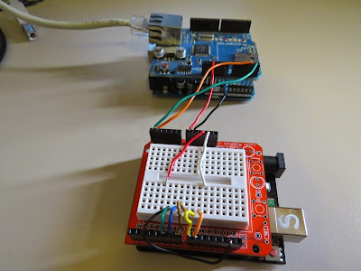
You can either wire up the TFT LCD module on a breadboard, or you can use a ProtoShield with mini-breadboard. It doesn't really matter how you hook it up, but make sure you double check the connections and the TFT specifications before you power it up. I have powered the Arduino Slave by connecting it to the Arduino Master (see fritzing sketch below).  
There is no reason why you couldn't just power the slave seperately. In fact this is probably the safer option. But I read that this power-sharing setup was ok, so I wanted to give it a go. I have no idea whether it would be suitable for a long term power project... so use it at your own risk. I tried using 4 x AA batteries to power this circuit, but found that the LCD screen would flicker. So then I tried a 9V battery, and noticed that the 5V voltage regulator was heating up more than I felt comfortable with. In the end, I settled with the USB option, and had no further issues. I am sure there are other possible options, and feel free to mention them in the comments below.  
Use the following fritzing sketch and tables to help you wire this circuit up.


Fritzing sketch


Arduino MASTER to SLAVE connection table


Arduino SLAVE to ITDB02-1.8SP TFT LCD


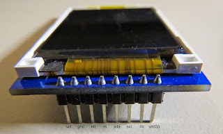
ITDB02-1.8SP TFT LCD Module Pictures


Project Pictures


If you like this page, please do me a favour and show your appreciation :

 
Visit my ArduinoBasics Google + page.
Follow me on Twitter by looking for ScottC @ArduinoBasics.
Have a look at my videos on my YouTube channel.


However, if you do not have a google profile...
Feel free to share this page with your friends in any way you see fit.

Display Your City’s Emotional State with Illuminated Snow

[Hunter] wanted to do something a bit more interesting for his holiday lights display last year. Rather than just animated lights, he wanted something that was driven by data. In this case, his display was based on the mood of people in his city. We’ve seen a very similar project in the past, but this one has a few notable differences.

The display runs off of an Arduino. [Hunter] is using an Ethernet shield to connect the Arduino to the Internet. It then monitors all of the latest tweets from users within a 15 mile radius of his area. The tweets are then forwarded to the Alchemy Sentiment API for analysis. The API uses various algorithms and detection methods to identify the overall sentiment within a body of text. [Hunter] is using it to determine the general mood indicated by the text of a given tweet.

Next [Hunter] needed a way to somehow display this information. He opted to use an LED strip. Since the range of sentiments is rather small, [Hunter] didn’t want to display the overall average sentiment. This value doesn’t change much over short periods of time, so it’s not very interesting to see. Instead, he plots the change made since the last sample. This results in a more obvious change to the LED display.

Another interesting thing to note about this project is that [Hunter] is using the snow in his yard to diffuse the light from the LEDs. He’s actually buried the strip under a layer of snow. This has the result of hiding the electronics, but blurring the light enough so you can’t see the individual LEDs. The effect is rather nice, and it’s something different to add to your holiday lights display. Be sure to check out the video below for a demonstration.


Filed under: Arduino Hacks, Holiday Hacks

Video mixing chess games on tv in Norway using Ethernet Shield

Heidi Røneid with an Arduino Ethernet microprocessor. (Photo: Tore Zakariassen, NRK)

When The Norwegian Broadcasting (NRK) planned the television broadcast of the Chess Olympiad 2014 in Tromsø, Norway, they encountered a challenge: how to mix video, graphics and the results of many ongoing chess games simultaneously, requiring 16 cameras for the games going on at the same time?

On their blog you can find a long and nice post about how they found the solution using Arduino Uno, Arduino Ethernet Shield and the library for Arduino to control such Atem switchers written by Kasper Skårhøj:

At first, the idea was to use a computer with a webcam for each of the 16 games, then mix video images, background animation and results in software on each of them.

Afterwards the finished mix of images would be streamed to separate channels in our web player, so that the online audience would be able to choose which game they wanted to follow. This solution would also provide our outside broadcasting van (OB van) with 16 finished video sources composed of video, graphics and results. This would make the complex job of mixing all video signals much easier.

After thorough thinking we came to the conclusion that for our web-audience, it would be better to skip the stream of individual games, and spend our resources on building websites that could present all games in the championship via HTML in real time. This would also give the audience the opportunity to scroll back and forth in the moves and recall all the previous games in the championship. We started working on it immediately, and you can find the result on our website nrk.no/sjakk.

Arduino Blog 28 Aug 19:14
arduino  chess  ethernet  featured  games  norway  shield  tv