When [::vtol::] wants to generate random numbers he doesn’t simply type rand() into his Arduino IDE, no, he builds a piece of art. It all starts with a knob, presumably connected to a potentiometer, which sets a frequency. An Arduino UNO takes the reading and generates a tone for an upward-facing speaker. A tiny ball bounces on that speaker where it occasionally collides with a piezoelectric element. The intervals between collisions become our sufficiently random number.
The generated number travels up the Rube Goldberg-esque machine to an LCD mounted at the top where a word, corresponding to our generated number, is displayed. As long as the button is held, a tone will continue to sound and words will be generated so poetry pours forth.
If this take on beat poetry doesn’t suit you, the construction of the Ball-O-Bol has an aesthetic quality that’s eye-catching, whereas projects like his Tape-Head Robot That Listens to the Floor and 8-Bit Digital Photo Gun showed the electronic guts front and center with their own appeal.
The “Navigation Thing“ was designed and built by [Jan Mrázek] as part of a night game activity for high school students during week-long seminar. A night-time path through a forest had stations with simple tasks, and the Navigation Thing used GPS, digital compass, a beeper, and a ring of RGB LEDs to provide a bit of “Wow factor” while guiding a group of students from one station to the next. The devices had a clear design direction:
“I wanted to build a device which a participant would find, insert batteries, and follow the beeping to find the next stop. Imagine the strong feeling of straying in the middle of the night in an unknown terrain far away from civilization trusting only a beeping thing you found. That was the feeling I wanted to achieve.”
The Navigation Things (there are six in total) guide users to fixed waypoints with GPS, a digital compass, and a ring of WS2812 LEDs — but the primary means of feedback to the user is a beeping that gets faster as you approach the destination. [Jan] had only four days to make all six units, which was doable. But as most of us know, delivering on a tight deadline is often less about doing the work you know about, and more about effectively handling the unexpected obstacles that inevitably pop up in the process.
The first real problem to solve was the beeping itself. “Beep faster as you get closer to the destination” seems like a simple task, but due to the way humans perceive things it’s more complex than it sounds. We perceive large changes easier than small incremental ones, so a straight linear change in beep frequency based on distance doesn’t work very well. Similar problems (and their solutions) exist whether you’re controlling volume, brightness, or just about anything else that humans perceive. Instead of encoding distance as a beep frequency, it’s much more effective to simply use beeps to signal overall changes: beep noticeably slower as you move away, but beep much faster as you get close.
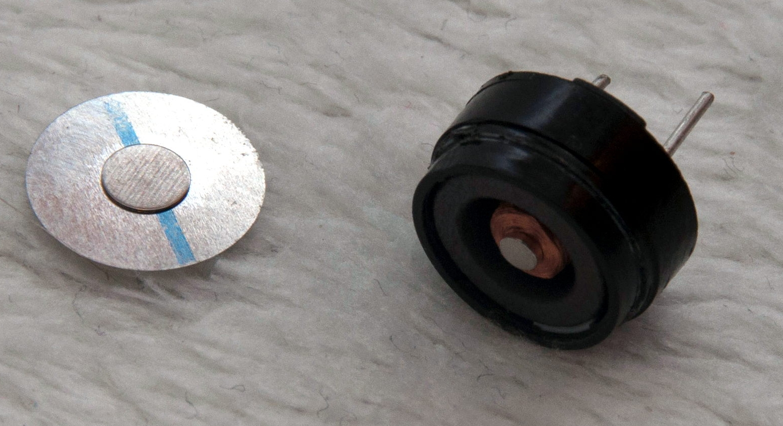
A “piezo” buzzer that was assumed to have no significant magnetic field, but in fact contained a magnet.
The other interesting problems were less straightforward and were related to the digital compass, or magnetometer. The first problem was that the piezo buzzers [Jan] sourced contained no actual piezo elements. They contained magnets – which interfered with the operation of the digital compass. After solving that, still more compass problems arose. When testing the final units in the field, the compass readings were not as expected and [Jan] had no idea why.
After careful troubleshooting, the culprit was found: the AA cells on the other side of the circuit board. Every AA cell has a faint (and slightly different) magnetic field, and the proximity and placement of the cells with respect to the magnetometer was causing the deviation. Happily, the fix was simple once the problem was understood: calibrate the compass every time new batteries are inserted.
If you’re interested in the Navigation Thing, check out the github repository. And on the topic of actual piezoelectric devices, piezos are implemented in a variety of clever ways. There are even piezo transformers and piezo vacuum pumps.
In our eyes, there isn’t a much higher calling for Arduinos than using them to make musical instruments. [victorh88] has elevated them to rock star status with his homemade electronic drum kit.
The kit uses an Arduino Mega because of the number of inputs [victorh88] included. It’s not quite Neil Peart-level, but it does have a kick drum, a pair of rack toms, a floor tom, a snare, a crash, a ride, and a hi-hat. With the exception of the hi-hat, all the pieces in the kit use a piezo element to detect the hit and play the appropriate sample based on [Evan Kale]’s code, which was built to turn a Rock Band controller into a MIDI drum kit. The hi-hat uses an LDR embedded in a flip-flop to properly mimic the range of an actual acoustic hi-hat. This is a good idea that we have seen before.
[victorh88] made all the drums and pads out of MDF with four layers of pet screen sandwiched in between. In theory, this kit should be able to take anything he can throw at it, including YYZ. The crash and ride cymbals are MDF with a layer of EVA foam on top. This serves two purposes: it absorbs the shock from the sticks and mutes the sound of wood against wood. After that, it was just a matter of attaching everything to a standard e-drum frame using the existing interfaces. Watch [victorh88] beat a tattoo after the break.
You may recall [AlphaPhoenix]’s recent electroshock Settlers of Catan expeditor. The idea with this less shocking build is to estimate the value of pi using the ratio of the area of a square sensor to a circular one. Simple piezo transducers serve as impact sensors that feed an Arduino and count the relative number of raindrops hitting the sensors. In the first video below, we see that as more data accumulates, the Arduino’s estimate of pi eventually converges on the well-known 3.14159 value. The second video has details of the math behind the method, plus a discussion of the real-world problems that cropped up during testing — turns out that waterproofing and grounding were both key to noise-free data from the sensor pads.
In the end, [AlphaPhoenix] isn’t proving anything new, but we like the method here and can see applications for it. What about using such sensors to detect individual popcorn kernels popping to demonstrate the Gaussian distribution? We also can’t help but think of other ways to measure raindrops; how about strain gauges that weigh the rainwater as it accumulates differentially in square and circular containers? Share your ideas in the comments below.
Marco Mauro is a physicist currently employed as Scientific Coordinator at Novaetech, the first Spin-off Company of the National Institute for Astrophysics (INAF) in Italy. He shared with us all the info about a project he’s been working on and based on Arduino Micro.
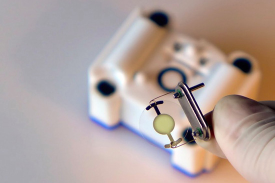
OpenQCM is a fully open source scientific microbalance capable of weighing mass deposition down to 1 billionth of gram:
The sensing core of the microbalance is a piezoelectric quartz crystal oscillator. The deposition of a very tiny mass on the surface causes the variation in the quartz frequency. openQCM belongs to a new generation of innovative smart sensor which boast high resolution and ultra high mass sensitivity. The open source strategy made the creation of openQCM available at low cost which represents a bit fraction of the cost of similar scientific products.
openQCM was built keeping in mind the emergent principles of the open source hardware movement. The open source hardware gives people the freedom to control their technology through the open exchange of all the project features, 3D design, electronics and software. The open hardware potentiality is even greater when it comes to hardware for scientific applications.
openQCM is exactly something like that, the first open hardware quartz crystal microbalance with applications in a wide range of scientific fields, such as chemical and biological sensing, material science.
openQCM has an Arduino Micro board inside at heart. By hacking the timer counter of the AtMega32U4 Arduino microcontroller, it is possible to measure the quartz crystal frequency variations using the 16 Mhz microprocessor clock. openQCM team has designed an Arduino Micro shield with an embedded quartz crystal oscillator driver circuit and a temperature sensor. The output of the quartz crystal oscillator driver is fed to the Arduino Micro timer counter and the analog value of the temperature sensor is fed to the analog pin of the board. This configuration allow you measure the quartz crystal frequency with a resolution of 1 Hz, which roughly corresponds to a mass resolution of 700 pg over the entire quartz surface in air.
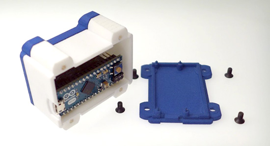
One of the major challenge of an open hardware project is that such devices require funding to prototype and manufacture. That’s why the openQCM team have selected the 3d printing technology to keep high quality and low cost. Using 3d printing to print out the prototypes via the SLS process from OS Formiga P100, P110, P395, and P730, the openQCM team created the device’s parts, which required a precision down to 60 µm.
The open source concept made openQCM publicly available so that anyone (scientists, technology enthusiast, makers, hobbyist …) can study, modify, and develop the hardware based on the original design. openQCM is now working and ready to win the heart of the scientific community and more.
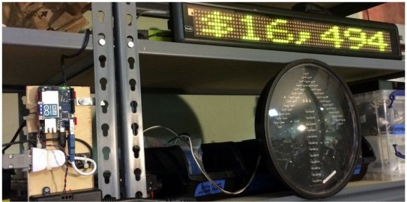
Keeping up with a kickstarter campaign can be quite a task, especially if your project is real (looking at you, Scribble Pen!) and you’re trying to keep up with product fabrication and all the other logistics involved in bringing a product to market. [macetech] are currently in the middle of a campaign themselves and built a loud, bright alert system to notify them of any new kickstarter backers.
The project uses a LED marquee to display the current number of backers, but every time a new backer contributes to the project, a blindingly bright green arrow traffic signal is illuminated and a piezo speaker plays a celebration tune. All of these devices are controlled by an Arduino Yun which, with its built-in Atheros chipset, easily connects to the network and monitors the kickstarter page for changes.
[macetech] used some interesting hardware to get everything to work together. They used a USB-to-RS232 cable with and FTDI chip to drive the LED marquee and a PowerSwitchTail 2 from Adafruit to drive the power-hungry traffic signal. Everything was put together in a presentable way for their workshop and works great! All of the source code is available on their project page, and you can check out their RGB LED Shades kickstarter campaign too.
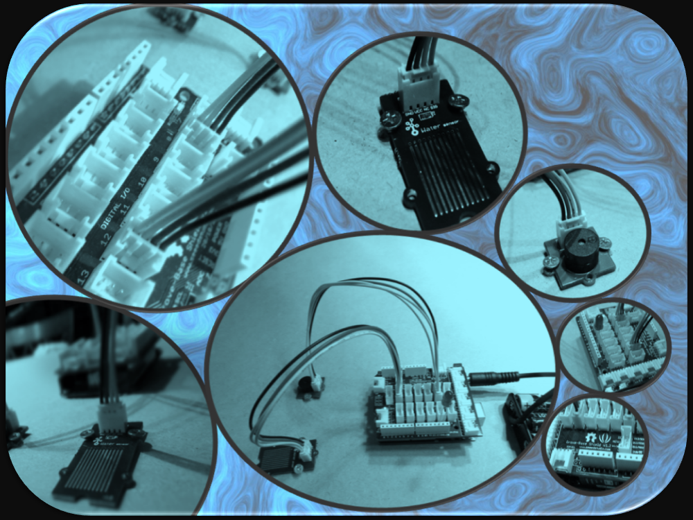
Connecting a water sensor to an Arduino is a great way to detect a leak, spill, flood, rain etc. It can be used to detect the presence, level, volume and/or the absence of water. While this could be used to remind you to water your plants, there is a better Grove sensor for that. The sensor has an array of exposed traces which will read LOW when water is detected. In this tutorial, we will connect the Water Sensor to Digital Pin 8 on the Arduino, and will enlist the very handy Grove Piezo buzzer and an LED to help identify when the Water sensor comes into contact with a source of water.
If you have a Grove Base Shield, you just have to connect the Grove Water Sensor to D8 on the shield, and the Buzzer to D12 on the Shield. My Grove base shield obstructs the onboard LED, so I will attach an LED to Digital pin 13. If you do not have a Grove base shield, then you should connect the Sensors as described in the tables below:
/* Grove Water Sensor sketch Written by ScottC 5th August 2014 Arduino IDE version 1.0.5 Website: http://arduinobasics.blogspot.com Description: Use Grove Water Sensor to detect leaks, floods, spills, rain etc. Credits: This sketch was inspired by this website: http://www.seeedstudio.com/wiki/Grove_-_Water_Sensor ------------------------------------------------------------- */ #define Grove_Water_Sensor 8 //Attach Water sensor to Arduino Digital Pin 8 #define Grove_Piezo_Buzzer 12 //Attach Piezo Buzzer to Arduino Digital Pin 12 #define LED 13 //Attach an LED to Digital Pin 13 (or use onboard LED) voidsetup(){ pinMode(Grove_Water_Sensor, INPUT); //The Water Sensor is an Input pinMode(Grove_Piezo_Buzzer, OUTPUT); //The Piezo Buzzer is an Output pinMode(LED, OUTPUT); //The LED is an Output }
voidloop(){ /* The water sensor will switch LOW when water is detected. Get the Arduino to illuminate the LED and activate the buzzer when water is detected, and switch both off when no water is present */ if(digitalRead(Grove_Water_Sensor) == LOW){ digitalWrite(LED,HIGH); digitalWrite(Grove_Piezo_Buzzer, HIGH); delay(2); digitalWrite(Grove_Piezo_Buzzer, LOW); delay(40); }else{ digitalWrite(Grove_Piezo_Buzzer, LOW); digitalWrite(LED,LOW); } }
The Video
If you liked this tutorial - please show your support :
Build a motion-sensing alarm by combining a few common components: an Arduino, a PIR sensor, a piezo buzzer, and a breadboard. All you need is some jumper wire to connect them all, and the software to run it.
With the Drum kit – Kit AI by Spikenzielabs you can build an electronic drum kit. The bundle contains all of the electronics, including the piezo sensors for the drum pads. You build the drum pads yourself, and then connect the Drum Kit – Kit AI to your computer to play sounds using your favorite audio software, or use the MIDI-out port to a connected drum synthesizer.
Roberto De Nicolò (aka Rodenic) has realized an useful tutorial video showing what he has called FingerDrum. Roberto has applied a piezo sensor to each finger of a glove, allowing the triggering of individual drum sounds from his midi expander. If you think the glove is unconfortable, check out the FingerPad and turn your mouse pad into a drum pad.