Posts with «enclosure» label

Spot This DIY Electronic Load’s Gracefully Hidden Hacks

Sometimes it’s necessary to make do with whatever parts one has on hand, but the results of squashing a square peg into a round hole are not always as elegant as [Juan Gg]’s programmable DC load with rotary encoder. [Juan] took a design for a programmable DC load and made it his own in quite a few different ways, including a slick 3D-printed enclosure and color faceplate.

The first thing to catch one’s eye might be that leftmost seven-segment digit. There is a simple reason it doesn’t match its neighbors: [Juan] had to use what he had available, and that meant a mismatched digit. Fortunately, 3D printing one’s own enclosure meant it could be gracefully worked into the design, instead of getting a Dremel or utility knife involved. The next is a bit less obvious: the display lacked a decimal point in the second digit position, so an LED tucked in underneath does the job. Finally, the knob on the right could reasonably be thought to be a rotary encoder, but it’s actually connected to a small DC motor. By biasing the motor with a small DC voltage applied to one lead and reading the resulting voltage from the other, the knob’s speed and direction can be detected, doing a serviceable job as rotary encoder substitute.

The project’s GitHub repository contains the Arduino code for [Juan]’s project, which has its roots in a design EEVblog detailed for an electronic load. For those of you who prefer your DIY rotary encoders to send discrete clicks and pulses instead of an analog voltage, a 3D printed wheel and two microswitches will do the job.

Stecchino Game is all about Balancing a Big Toothpick

Stecchino demo by the creator

Self-described “Inventor Dad” [pepelepoisson]’s project is called Stecchino (English translation link here) and it’s an Arduino-based physical balancing game that aims to be intuitive to use and play for all ages. Using the Stecchino (‘toothpick’ in Italian) consists of balancing the device on your hand and trying to keep it upright for as long as possible. The LED strip fills up as time passes, and it keeps records of high scores. It was specifically designed to be instantly understood and simple to use by people of all ages, and we think it has succeeded in this brilliantly.

To sense orientation and movement, Stecchino uses an MPU-6050 gyro and accelerometer board. An RGB LED strip gives feedback, and it includes a small li-po cell and charger board for easy recharging via USB. The enclosure is made from a few layers of laser-cut and laser-engraved material that also holds the components in place. The WS2828B LED strip used is technically a 5 V unit, but [pepelepoisson] found that feeding them direct from the 3.7 V cell works just fine; it’s not until the cell drops to about three volts that things start to glitch out. All source code and design files are on GitHub.

Games are great, and the wonderful options available to people today allow for all kinds of interesting experimentation like a blind version of tag, or putting new twists on old classics like testing speed instead of strength.

Navigation Thing: Four Days, Three Problems, and Fake Piezos

The Navigation Thing was designed and built by [Jan Mrázek] as part of a night game activity for high school students during week-long seminar. A night-time path through a forest had stations with simple tasks, and the Navigation Thing used GPS, digital compass, a beeper, and a ring of RGB LEDs to provide a bit of “Wow factor” while guiding a group of students from one station to the next. The devices had a clear design direction:

“I wanted to build a device which a participant would find, insert batteries, and follow the beeping to find the next stop. Imagine the strong feeling of straying in the middle of the night in an unknown terrain far away from civilization trusting only a beeping thing you found. That was the feeling I wanted to achieve.”

The Navigation Things (there are six in total) guide users to fixed waypoints with GPS, a digital compass, and a ring of WS2812 LEDs — but the primary means of feedback to the user is a beeping that gets faster as you approach the destination. [Jan] had only four days to make all six units, which was doable. But as most of us know, delivering on a tight deadline is often less about doing the work you know about, and more about effectively handling the unexpected obstacles that inevitably pop up in the process.

The first real problem to solve was the beeping itself. “Beep faster as you get closer to the destination” seems like a simple task, but due to the way humans perceive things it’s more complex than it sounds. We perceive large changes easier than small incremental ones, so a straight linear change in beep frequency based on distance doesn’t work very well. Similar problems (and their solutions) exist whether you’re controlling volume, brightness, or just about anything else that humans perceive. Instead of encoding distance as a beep frequency, it’s much more effective to simply use beeps to signal overall changes: beep noticeably slower as you move away, but beep much faster as you get close.

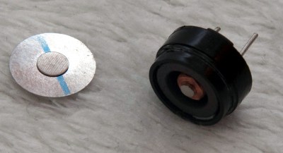
A “piezo” buzzer that was assumed to have no significant magnetic field, but in fact contained a magnet.

The other interesting problems were less straightforward and were related to the digital compass, or magnetometer. The first problem was that the piezo buzzers [Jan] sourced contained no actual piezo elements. They contained magnets – which interfered with the operation of the digital compass. After solving that, still more compass problems arose. When testing the final units in the field, the compass readings were not as expected and [Jan] had no idea why.

After careful troubleshooting, the culprit was found: the AA cells on the other side of the circuit board. Every AA cell has a faint (and slightly different) magnetic field, and the proximity and placement of the cells with respect to the magnetometer was causing the deviation. Happily, the fix was simple once the problem was understood: calibrate the compass every time new batteries are inserted.

If you’re interested in the Navigation Thing, check out the github repository. And on the topic of actual piezoelectric devices, piezos are implemented in a variety of clever ways. There are even piezo transformers and piezo vacuum pumps.


Filed under: gps hacks, misc hacks

Hackaday Links: November 22, 2015

There’s a new documentary series on Al Jazeera called Rebel Geeks that looks at the people who make the stuff everyone uses. The latest 25-minute part of the series is with [Massimo], chief of the arduino.cc camp. Upcoming episodes include Twitter co-creator [Evan Henshaw-Plath] and people in the Madrid government who are trying to build a direct democracy for the city on the Internet.

Despite being a WiFi device, the ESP8266 is surprisingly great at being an Internet of Thing. The only problem is the range. No worries; you can use the ESP as a WiFi repeater that will get you about 0.5km further for each additional repeater node. Power is of course required, but you can stuff everything inside a cell phone charger.

I’ve said it before and I’ll say it again: the most common use for the Raspberry Pi is a vintage console emulator. Now there’s a Kickstarter for a dedicated tabletop Raspi emulation case that actually looks good.

Pogo pins are the go-to solution for putting firmware on hundreds of boards. These tiny spring-loaded pins give you a programming rig that’s easy to attach and detach without any soldering whatsoever. [Tom] needed to program a few dozen boards in a short amount of time, didn’t have any pogo pins, and didn’t want to solder a header to each board. The solution? Pull the pins out of a female header. It works in a pinch, but you probably want a better solution for a more permanent setup.

Half of building a PCB is getting parts and pinouts right. [Josef] is working on a tool to at least semi-automate the importing of pinout tables from datasheets into KiCad. This is a very, very hard problem, and if it’s half right half the time, that’s a tremendous accomplishment.

Last summer, [Voja] wrote something for the blog on building enclosures from FR4. Over on Hackaday.io he’s working on a project, and it’s time for that project to get an enclosure. The results are amazing and leave us wondering why we don’t see this technique more often.


Filed under: Hackaday Columns, Hackaday links

Tracking Solar Brightness with a Homemade Sun Logger

The Sun Logger, a data logging device, combines several components we’ve used in previous Weekend Projects. You may recognize the light-sensitive photoresistor (Optical Tremolo Box) and the Arduino Uno microcontroller (Touchless 3D Tracking Interface). These parts, when combined with a 74AHC125 Level Shifter and SD card socket mounted on a homemade “shield,” will record the levels of light shining down on your project box. That data, recorded every 15 seconds to the SD card, can be exported later to any popular spreadsheet software and graphed, giving you a visual representation of light changes over time. This data could aid in knowing where best to plant a garden, or simply to understand changes of light intensity throughout the seasons in your micro-climate.

And while this project is readymade for recording levels of sunlight, the Arduino has a total of six analog inputs (labeled A0 – A5) and could easily record other variables. For example temperature, motion, or barometric pressure. Makers looking for a mid-level Arduino build, or knowledgeable coders looking to solder together their first homemade shield, the Sun Logger is a great project to build!


Filed under: Arduino, MAKE Projects, Weekend Projects

DIY custom rugged Arduino

In this instructable, Dustin Andrews shows how to make a custom Arduino board, equipped with a lcd, a buzzer and a solid enclosure. Dustin’s goal has been to design a rugged Arduino version, that can be employed “as is” in many practical project, in place of a less solid breadboard-based solution.

The project is released under Creative Commons CC-BY license.

[Via: Instructables]

Arduino Blog 29 May 19:40