 Introduction:
This project utilises the HC-SR04 ultrasonic sensor to scan for nearby objects. You can program the Arduino to sound an alarm when the sensor detects an object within a specific vicinity. Connecting it to a computer allows data to be plotted to make a simple sonar scanner. The scanning ability is made possible through the use of a hobby servo motor SG-5010, and an Adafruit motor shield v1.0.
This project could easily be extended to provide object avoidance for any robotics project. This tutorial was designed so that you could see how the components interact, and also to see how you can use and expand the functionality of the motor shield.
 Parts Required:Freetronics Eleven
 or any compatible Arduino.
Adafruit
motor shield v1.0
HC-SR04 Ultrasonic Sensor
MG-995 or SG-5010 Standard servo
Mini Breadboard 4.5cm x 3.5cm
Female header pins to allow easy access to the analog pins on the Motor Shield
Piezo buzzer - to sound alarm
9V Battery and
Battery ClipWiresto connect it all together
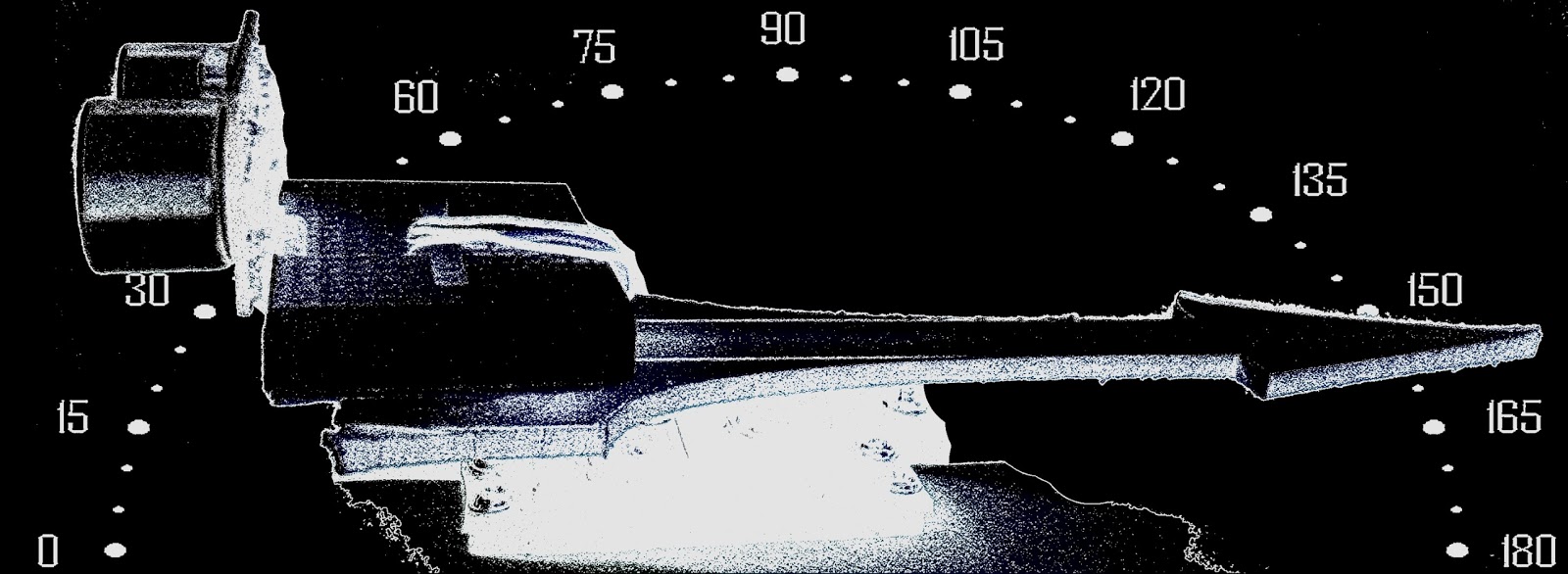
Gauge parts:Paper (to print the face of the gauge), and some glue to stick it to the wood.
MDF Standard panel (3mm width) - for the top and base of the gauge, and the pointer.
Galvanized bracket (25x25x40mm)
Timber screws: Hinge-long threads csk head Phillips drive (4G x 12mm)
Velcro dots - to allow temporary application of the mini-breadboard to the gauge.
The gauge was used as a customisable housing for the Arduino and related parts, and to provide some visual feedback of the servo position.
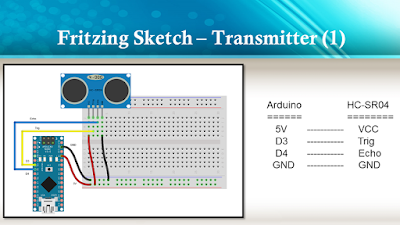
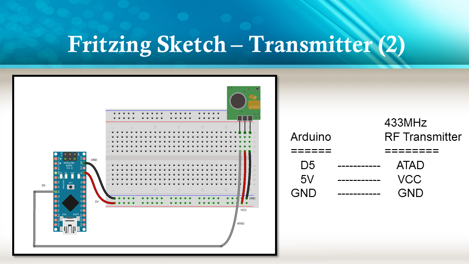
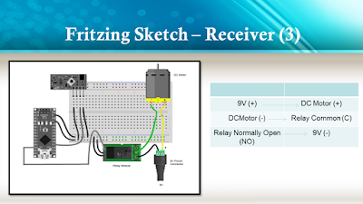
The Video:The Arduino Sketch: Part of the sketch above was created using Fritzing.
The Servo motor can be connected to either of the Servo motor pins (Digital 9 or 10). In this case, the Servo is attached to digital pin 10.Make sure you read the servo motor data sheet and identify the VCC (5V), GND, and Signal connectors. Not all servos have the same colour wires. My servo motor has a white signal wire, a red VCC wire and a black GND wire.
Also when connecting your wires to the HC-SR04, pay attention to the front of the sensor. It will identify the pins for you. Make sure you have the sensor facing the correct way. In this sketch, the sensor is actually facing towards you.
In this sketch - we connect the
Echo pin to Analog pin 0 (A0).
Trigger pin to Analog pin 1 (A1)
VCC to a 5V line/pin
and GND to a GND line/pin
Pay attention to your motor shield, I have seen some pictures on the internet where the 5V and GND are reversed.
Arduino Code:You can download the Arduino IDE from
this site.
The motor shield requires the
Adafruit motor shield driver library to be installed into the Arduino IDE.
 1
 2
 3
 4
 5
 6
 7
 8
 9
 10
 11
 12
 13
 14
 15
 16
 17
 18
 19
 20
 21
 22
 23
 24
 25
 26
 27
 28
 29
 30
 31
 32
 33
 34
 35
 36
 37
 38
 39
 40
 41
 42
 43
 44
 45
 46
 47
 48
 49
 50
 51
 52
 53
 54
 55
 56
 57
 58
 59
 60
 61
 62
 63
 64
 65
 66
 67
 68
 69
 70
 71
 72
 73
 74
 75
 76
 77
 78
 79
 80
 81
 82
 83
 84
 85
 86
 87
 88
 89
 90
 91
 92
 93
 94
 95
 96
 97
 98
 99
100
101
102
103
104 | /* ArduinoBasics: Sonar Project - Created by Scott C on 10 Jan 2013
http://arduinobasics.blogspot.com/2013/01/arduino-basics-sonar-project-tutorial.html
This project uses the Adafruit Motor shield library (copyright Adafruit Industries LLC, 2009
this code is public domain, enjoy!)
The HC-SR04 sensor uses some code from the following sources:
From Virtualmix: http://goo.gl/kJ8Gl
Modified by Winkle ink here: http://winkleink.blogspot.com.au/2012/05/arduino-hc-sr04-ultrasonic-distance.html
And modified further by ScottC here: http://arduinobasics.blogspot.com/
on 10 Nov 2012.
*/
#include <AFMotor.h>
#include <Servo.h>
// DC hobby servo
Servo servo1;
/* The servo minimum and maximum angle rotation */
static const int minAngle = 0;
static const int maxAngle = 176;
int servoAngle;
int servoPos;
int servoPin = 10;
/* Define pins for HC-SR04 ultrasonic sensor */
#define echoPin A0 // Echo Pin = Analog Pin 0
#define trigPin A1 // Trigger Pin = Analog Pin 1
#define LEDPin 13 // Onboard LED
long duration; // Duration used to calculate distance
long HR_dist=0; // Calculated Distance
int HR_angle=0; // The angle in which the servo/sensor is pointing
int HR_dir=1; // Used to change the direction of the servo/sensor
int minimumRange=5; //Minimum Sonar range
int maximumRange=200; //Maximum Sonar Range
/*--------------------SETUP()------------------------*/
void setup() {
//Begin Serial communication using a 9600 baud rate
Serial.begin (9600);
// Tell the arduino that the servo is attached to Digital pin 10.
servo1.attach(servoPin);
//Setup the trigger and Echo pins of the HC-SR04 sensor
pinMode(trigPin, OUTPUT);
pinMode(echoPin, INPUT);
pinMode(LEDPin, OUTPUT); // Use LED indicator (if required)
}
/*----------------------LOOP()--------------------------*/
void loop() {
/* check if data has been sent from the computer: */
if (Serial.available()) {
/* This expects an integer from the Serial buffer */
HR_angle = Serial.parseInt();
/* If the angle provided is 0 or greater, then move servo to that
position/angle and then get a reading from the ultrasonic sensor */
if(HR_angle>-1){
/*Make sure that the angle provided does not go beyond the capabilities
of the Servo. This can also be used to calibrate the servo angle */
servoPos = constrain(map(HR_angle, 0,180,minAngle,maxAngle),minAngle,maxAngle);
servo1.write(servoPos);
/* Call the getDistance function to take a reading from the Ultrasonic sensor */
getDistance();
}
}
}
/*--------------------getDistance() FUNCTION ---------------*/
void getDistance(){
/* The following trigPin/echoPin cycle is used to determine the
distance of the nearest object by bouncing soundwaves off of it. */
digitalWrite(trigPin, LOW);
delayMicroseconds(2);
digitalWrite(trigPin, HIGH);
delayMicroseconds(10);
digitalWrite(trigPin, LOW);
duration = pulseIn(echoPin, HIGH);
//Calculate the distance (in cm) based on the speed of sound.
HR_dist = duration/58.2;
/*Send the reading from the ultrasonic sensor to the computer */
if (HR_dist >= maximumRange || HR_dist <= minimumRange){
/* Send a 0 to computer and Turn LED ON to indicate "out of range" */
Serial.println("0");
digitalWrite(LEDPin, HIGH);
} else {
/* Send the distance to the computer using Serial protocol, and
turn LED OFF to indicate successful reading. */
Serial.println(HR_dist);
digitalWrite(LEDPin, LOW);
}
} |
Servo Angles: You will notice on line 22, the maximum servo angle used was 176. This value was obtained through trial and error (see below).
Calibrating the servo angles
You may need to calibrate your servo in order to move through an angle of 0 to 180 degrees without straining the motor. Go to line 21-22 and change the minAngle to 0 and the maxAngle to 180. Once you load the sketch to the Arduino/Freetronics ELEVEN, you can then open the Serial Monitor and type a value like 10 <enter>, and then keep reducing it until you get to 0. If you hear the servo motor straining, then move it back up to a safe value and change the minimum servo angle to that value. Do the same for the maximum value.
In this example, the servo's minAngle value was 0, and maxAngle value was 176 after calibration, however, as you can see from the video, the physical range of the servo turned out to be 0 to 180 degrees.
The Processing SketchYou can download the Processing IDE from
this site.
 1
 2
 3
 4
 5
 6
 7
 8
 9
 10
 11
 12
 13
 14
 15
 16
 17
 18
 19
 20
 21
 22
 23
 24
 25
 26
 27
 28
 29
 30
 31
 32
 33
 34
 35
 36
 37
 38
 39
 40
 41
 42
 43
 44
 45
 46
 47
 48
 49
 50
 51
 52
 53
 54
 55
 56
 57
 58
 59
 60
 61
 62
 63
 64
 65
 66
 67
 68
 69
 70
 71
 72
 73
 74
 75
 76
 77
 78
 79
 80
 81
 82
 83
 84
 85
 86
 87
 88
 89
 90
 91
 92
 93
 94
 95
 96
 97
 98
 99
100
101
102
103
104
105
106
107
108
109
110 | /* Created by ScottC on 10 Jan 2013
http://arduinobasics.blogspot.com/2013/01/arduino-basics-sonar-project-tutorial.html
*/
import processing.serial.*;
int distance;
int angle=0;
int direction=1;
int[] alphaVal = new int[100]; // used to fade the lines
int[] distance2 = new int[100]; // used to store the line lengths
int lineSize = 4; // line length multiplier (makes it longer)
String comPortString;
Serial comPort;
/*---------------------SETUP---------------------------*/
void setup( ) {
size(displayWidth,displayHeight); //allows fullscreen view
smooth();
background(0); // set the background to black
/*Open the serial port for communication with the Arduino
Make sure the COM port is correct - I am using COM port 8 */
comPort = new Serial(this, "COM8", 9600);
comPort.bufferUntil('\n'); // Trigger a SerialEvent on new line
/*Initialise the line alphaValues to 0 (ie not visible) */
for(int i=0; i<91; i++){
alphaVal[i] = 0;
}
}
/*---------------------DRAW-----------------*/
void draw( ) {
background(0); //clear the screen
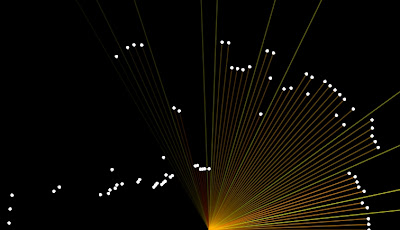
/*Draw each line and dot */
for(int i=0; i<91; i++){
/*Gradually fade each line */
alphaVal[i]=alphaVal[i]-4;
/*Once it gets to 0, keep it there */
if(alphaVal[i]<0){
alphaVal[i]=0;
}
/*The colour of the line will change depending on the distance */
stroke(255,distance2[i],0,alphaVal[i]);
/* Use a line thickness of 2 (strokeweight) to draw the line that fans
out from the bottom center of the screen. */
strokeWeight(2);
line(width/2, height, (width/2)-cos(radians(i*2))*(distance2[i]*lineSize), height-sin(radians(i*2))*(distance2[i]*lineSize));
/* Draw the white dot at the end of the line which does not fade */
stroke(255);
strokeWeight(1);
ellipse((width/2)-cos(radians(i*2))*(distance2[i]*lineSize), height-sin(radians(i*2))*(distance2[i]*lineSize),5,5);
}
}
/* A mouse press starts the scan. There is no stop button */
void mousePressed(){
sendAngle();
}
/*When the computer receives a value from the Arduino, it will update the line positions */
void serialEvent(Serial cPort){
comPortString = cPort.readStringUntil('\n');
if(comPortString != null) {
comPortString=trim(comPortString);
/* Use the distance received by the Arduino to modify the lines */
distance = int(map(Integer.parseInt(comPortString),1,200,1,height));
drawSonar(angle,distance);
/* Send the next angle to be measured by the Arduino */
sendAngle();
}
}
/*---------------------------sendAngle() FUNCTION----------------*/
void sendAngle(){
//Send the angle to the Arduino. The fullstop at the end is necessary.
comPort.write(angle+".");
/*Increment the angle for the next time round. Making sure that the angle sent
does not exceed the servo limits. The "direction" variable allows the servo
to have a sweeping action.*/
angle=angle+(2*direction);
if(angle>178||angle<1){
direction=direction*-1;
}
}
/*-----------------sketchFullScreen(): Allows for FullScreen view------*/
boolean sketchFullScreen() {
return true;
}
/*----------------- drawSonar(): update the line/dot positions---------*/
void drawSonar(int sonAngle, int newDist){
alphaVal[sonAngle/2] = 180;
distance2[sonAngle/2] = newDist;
}
|


 The build itself is uncomplicated and can be replicated with ease. A servo motor helps flip the lid open and close. This is triggered by an ultrasonic ping sensor, which responds when someone waves a hand in front of the trash can. A second ping sensor helps inform the user when it is full and needs to be emptied. A Leonardo with the


