Posts with «receiver» label

DIY Arduino Due TEA5767 FM Radio

Older hackers will remember that a crystal set radio receiver was often one of the first projects attempted.  Times have changed, but there’s still something magical about gathering invisible signals from the air and listening to the radio on a homemade receiver. [mircemk] has brought the idea right up to date by building an FM radio with an OLED display, controlled with a rotary encoder.

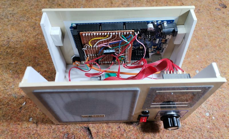
The design is fairly straightforward, based as it is on another project that [mircemk] found on a Chinese site, but the build looks very slick and would take pride of place on any hacker’s workbench. An Arduino Due forms the heart of the project, controlling a TEA5767 module, an SH1106 128×64 pixel OLED display and a rotary encoder. The sound signal is passed through an LM4811 headphone amplifier for private listening, and a PAM8403 Class D audio amplifier for the built-in loudspeaker. The enclosure is made from PVC panels, and accented with colored adhesive tape for style.

It’s easier than ever before to quickly put together projects like this by connecting pre-built modules and downloading code from the Internet, but that doesn’t mean it’s not a worthwhile way to improve your skills and make some useful devices like this one. There are so many resources available to us these days and standing on the shoulders of giants has always been a great way to see farther.

We’ve shown some other radio projects using Arduinos and the TEA5767 IC in the past, such as this one on a tidy custom PCB, and this one built into an old radio case.

Hack a Day 09 Oct 06:00

FM Radio from Scratch using an Arduino

Building radio receivers from scratch is still a popular project since it can be done largely with off-the-shelf discrete components and a wire long enough for the bands that the radio will receive. That’s good enough for AM radio, anyway, but you’ll need to try this DIY FM receiver if you want to listen to something more culturally relevant.

Receiving frequency-modulated radio waves is typically more difficult than their amplitude-modulated cousins because the circuitry necessary to demodulate an FM signal needs a frequency-to-voltage conversion that isn’t necessary with AM. For this build, [hesam.moshiri] uses a TEA5767 FM chip because of its ability to communicate over I2C. He also integrated a 3W amplifier into this build, and everything is controlled by an Arduino including a small LCD screen which displays the current tuned frequency. With the addition of a small 5V power supply, it’s a tidy and compact build as well.

While the FM receiver in this project wasn’t built from scratch like some AM receivers we’ve seen, it’s still an interesting build because of the small size, I2C capability, and also because all of the circuit schematics are available for all of the components in the build. For those reasons, it could be a great gateway project into more complex FM builds.

Hack a Day 05 Dec 00:00

Prextron CHAIN BLOCKS - Arduino Nano controlled Ultrasonic sensor that switches a motor wirelessly using 433MHz RF modules and a relay board.


Description

In this tutorial, I will be evaluating Prextron CHAIN blocks – a new system that allows you to connect your sensors and actuators to an Arduino NANO using clever 3D-printed prototyping boards that can be stacked sideways. This very modular system makes it easy to connect, disconnect and replace project components, and eliminate the “rats nest of wires” common to many advanced Arduino projects. CHAIN BLOCKS are open, which means that you can incorporate any of your sensors or actuators to these prototyping boards, and you can decide which specific pin on Arduino you plan to use. The CHAIN BLOCK connections prevent or reduce common connection mistakes, which make them ideal for class-room projects and learning activities.

I am going to set up a project to put these CHAIN BLOCKs to the test:
When I place my hand in-front of an Ultrasonic sensor, the Arduino will transmit a signal wirelessly to another Arduino, and consequently turn on a motor.


Parts Required:

You need the following Prextron Chain Blocks


Please note: You may need to solder the module wires to the CHAIN BLOCK protoboard.


Arduino Libraries and IDE

This project does not use any libraries. However, you will need to upload Arduino code to the Arduino. For this you will need the Arduino IDE which can be obtained from the official Arduino website:
https://www.arduino.cc/en/main/software


ARDUINO CODE: RF Transmitter


ARDUINO CODE: RF Receiver


Fritzing diagrams for Transmitter


Fritzing diagrams for Receiver


Concluding comments

The purpose of this project was to evaluate Prextron CHAIN BLOCKs and put them to the test. Here is what I thought of CHAIN BLOCKS at the time of evaluation. Some of my points mentioned below may no longer apply to the current product. It may have evolved / improved since then. So please take that into consideration


What I liked about Chain Blocks

  • The design is simple, the product is simple.
  • Once the Chain Blocks were all assembled, they were very easy to connect to each other.
  • I can really see the benefit of Chain Blocks in a teaching environment, because it simplifies the connection process, and reduces connection mixups.
  • It was good to see that the blocks come in different colours, which means that you can set up different colour schemes for different types of modules.
  • You can incorporate pretty much any sensor or Actuator into the Chain block which is very appealing.
  • You also have the flexibility of choosing which pins you plan to use on the Arduino.
  • Projects look a lot neater, because you no longer have the rats nest of wires.
  • The Blocks lock into each other which means that they are much easier to transport/carry.


What I did not like about Chain Blocks

  • In most cases, the Chain Block protoboard lanes were not numbered, which increased the chances of making mistakes when soldering
  • The need to solder modules to the protoboard, may be a discouragement for some people.
  • I would have liked a choice of different size Chain blocks. Some of the sensors did not fit nicely into the Square blocks.
  • Prextron really need to work on their website if they plan to get serious with this product: Webpage has incomplete functionality or irrelevant links etc etc.


Thank you very much to Prextron for providing the CHAIN BLOCKS used in this tutorial, and allowing me to try out their product. If you are interested in trying them yourself, then make sure to visit them at:


If you like this page, please do me a favour and show your appreciation :

 
Visit my ArduinoBasics Google + page.
Follow me on Twitter by looking for ScottC @ArduinoBasics.
I can also be found on Pinterest and Instagram.
Have a look at my videos on my YouTube channel.


433 MHz RF module with Arduino Tutorial 2


There are 4 parts to this tutorial:
To get the most out of this tutorial - it is best to start at tutorial Part 1, and then progress to Part 2 then Part 3 and then do Part 4 last. Doing the RF tutorials in this order will help you to understand the process better.


Project 2: RF Remote Copy

In the previous project, we transmitted a signal wirelessly from one Arduino to another. It was there to help troubleshoot communication between the modules. It was important to start with a very short distance (1-2 cm) and then move the RF modules further apart to test the range. The range can be extended by soldering an antenna to the module, or by experimenting with different voltage supplies to the modules (making sure to keep within the voltage limits of the modules.)
In this project - we aim to receive a signal from an RF remote. The remote that I am using is a Mercator Remote Controller for a Fan/Light. (Remote controller code is FRM94). It is important that you use a remote that transmits at the same frequency as your receiver. In this case, my remote just happens to use a frequency of 433MHz. I was able to receive RF signals from from a distance of about 30cm without an antenna (from my remote to the receiver).


Video


Here are the parts that you will need to carry out this project:
 

Parts Required


Remote Controller


You can quickly test your remote, by pressing one of the buttons in close proximity to the RF receiver (using the same sketch as in Project 1), and you should see the LED flicker on an off in response to the button press. If you don't see the LED flickering, then this project will not work for you.

Here is a picture of the remote controller that I am using:


Arduino Sketch - Remote Receiver

The following sketch will make the Arduino wait until a signal is detected from the remote (or other 433 MHz RF device). Once triggered, it will turn the LED ON, and start to collect and store the signal data into an array.
I did my best to keep the signal reading section of the sketch free from other functions or interruptions.The aim is to get the Arduino to focus on reading ONLY... and once the reading phase is complete, it will report the signal data to the Serial monitor. So you will need to have the Serial monitor open when you press the remote control button.
The remote control signal will be made up of HIGH and LOW signals - which I will try to illustrate later in the tutorial. But for now, all you need to know is that the Signal will alternate between HIGH and LOW signals, and that they can be different lengths.
This sketch aims to identify how long each LOW and HIGH signal is (to make up the complete RF remote signal). I have chosen to capture 500 data points(or 250 LOW/HIGH combinations).You may wish to increase or decrease the dataSize variable to accomodate your specific RF signal. In my case, I only really needed 300 data points, because there was a "flat" signal for the last 200 data points (characterised by 200 repetitions of a LOW signal length of 0 and HIGH signal length of 255)

--------------------------------------------------


Receiver Fritzing Sketch


Results

After pressing the button on the RF remote, the data signal is printed to the Serial Monitor. You can copy the data to a spreadsheet program for review. This is an example of the signal produced after pushing the button on the remote for turning the fan/light on.
The following code was produced from pushing the button responsible for turning the light off:
The code sequence above may seem a bit random until you start graphing it. I grabbed the LOW column - and produced the following chart:
The chart above is a bit messy - mainly because the timing is slightly out... in that sometimes it can squeeze an extra read from a particular signal. But what is important to note here is that you can differentiate a LONG signal from a SHORT signal. I have drawn a couple of red dotted lines where I believe most of the readings tend to sit. I then used a formula in the spreadsheet to calibrate the readings and make them a bit more uniform. For example, if the length of the signal was greater than 4 analogReads, then I converted this to 6. If it was less than 4 analogReads, then I converted it to 2. I used a frequency table to help decide on the cutoff value of 4, and just decided to pick the two values (2 for short, and 6 for long) based on the frequency tables below. I could have chosen 5 as the LONG value, but there were more 6's overall.

  **The meaning of "frequency" in the following tables relate to the "number of times" a specific signal length is recorded.


And this is the resulting chart:

You will notice that the pattern is quite repetitive. I helped to identify the sections with vertical red lines (near the bottom of the chart). In other words, the signal produced by the remote is repeated 6 times.
I then did the same for the HIGH signal column and combined the two to create the following chart:


You will notice that the HIGH signals also have a repetitive pattern, however have a Very long length at the end of each section. This is almost a break to separate each section.
This is what a single section looks like zoomed in:


SL = [Short LOW] signal. - or short blue bar
SH = [Short HIGH] signal - or short yellow bar
LL = [Long LOW] signal - or long blue bar
LH = [Long HIGH] signal - or long yellow bar
VLH = [Very long HIGH} signal - or very long yellow bar (~92 analogReads in length)


  You will notice that there are only about 6 different combinations of the signals mentioned above. We can use this to create a coding system as described below:


We can use this coding system to describe the signals. The charts below show the difference between turning the LIGHT ON and LIGHT OFF.


PLEASE NOTE: You may notice when you copy the signals from the Serial monitor that you get a series of (0,255) combinations. This is actually a timeout sequence - which generally occurs after the signal is complete.

 Here is an example of what I mean.


This is the end of tutorial 2. In the next tutorial, we will use the code acquired from the remote to turn the FAN LIGHT on and off (using the 433 MHz RF transmitter).

Click here for Tutorial 3

ScottC 26 Jun 18:05

433 MHz RF module with Arduino Tutorial 2

Project 2: RF Remote Copy

In the previous project, we transmitted a signal wirelessly from one Arduino to another. It was there to help troubleshoot communication between the modules. It was important to start with a very short distance (1-2 cm) and then move the RF modules further apart to test the range. The range can be extended by soldering an antenna to the module, or by experimenting with different voltage supplies to the modules (making sure to keep within the voltage limits of the modules.)

In this project - we aim to receive a signal from an RF remote. The remote that I am using is a Mercator Remote Controller for a Fan/Light. (Remote controller code is FRM94). It is important that you use a remote that transmits at the same frequency as your receiver. In this case, my remote just happens to use a frequency of 433MHz. I was able to receive RF signals from from a distance of about 30cm without an antenna (from my remote to the receiver).


Video


Here are the parts that you will need to carry out this project:
 

Parts Required


Remote Controller

You can quickly test your remote, by pressing one of the buttons in close proximity to the RF receiver (using the same sketch as in Project 1), and you should see the LED flicker on an off in response to the button press. If you don't see the LED flickering, then this project will not work for you.

Here is a picture of the remote controller that I am using:


Arduino Sketch - Remote Receiver

The following sketch will make the Arduino wait until a signal is detected from the remote (or other 433 MHz RF device). Once triggered, it will turn the LED ON, and start to collect and store the signal data into an array.

I did my best to keep the signal reading section of the sketch free from other functions or interruptions.The aim is to get the Arduino to focus on reading ONLY... and once the reading phase is complete, it will report the signal data to the Serial monitor. So you will need to have the Serial monitor open when you press the remote control button.

The remote control signal will be made up of HIGH and LOW signals - which I will try to illustrate later in the tutorial. But for now, all you need to know is that the Signal will alternate between HIGH and LOW signals, and that they can be different lengths.

This sketch aims to identify how long each LOW and HIGH signal is (to make up the complete RF remote signal). I have chosen to capture 500 data points(or 250 LOW/HIGH combinations).You may wish to increase or decrease the dataSize variable to accomodate your specific RF signal. In my case, I only really needed 300 data points, because there was a "flat" signal for the last 200 data points (characterised by 200 repetitions of a LOW signal length of 0 and HIGH signal length of 255)


--------------------------------------------------
 1
2
3
4
5
6
7
8
9
10
11
12
13
14
15
16
17
18
19
20
21
22
23
24
25
26
27
28
29
30
31
32
33
34
35
36
37
38
39
40
41
42
43
44
45
46
47
48
49
50
51
52
53
54
55
56
57
58
59
60
61
62
63
64
65
66
67
68
69
70
71
72
73
74
75
76
77
78
79
80
81
82
83
84
85
86
87


/* 
  RF Remote Capture sketch 
     Written by ScottC 24 Jun 2014
     Arduino IDE version 1.0.5
     Website: http://arduinobasics.blogspot.com
     Receiver: XY-MK-5V
     Description: Use Arduino to Receive RF Remote signal          
 ------------------------------------------------------------- */

 const int dataSize = 500; //Arduino memory is limited (max=1700)
 byte storedData[dataSize]; //Create an array to store the data
 #define ledPin 13           //Onboard LED = digital pin 13
 #define rfReceivePin A0     //RF Receiver data pin = Analog pin 0
 const unsigned int upperThreshold = 100; //upper threshold value
 const unsigned int lowerThreshold = 80; //lower threshold value
 int maxSignalLength = 255; //Set the maximum length of the signal
 int dataCounter = 0; //Variable to measure the length of the signal
 unsigned long startTime=0; //Variable to record the start time
 unsigned long endTime=0; //Variable to record the end time
 unsigned long signalDuration=0; //Variable to record signal reading time
 

 void setup(){
  Serial.begin(9600);
  pinMode(ledPin, OUTPUT);
  
  /* The following code will only run ONCE --------------
  ---Press the reset button on the Arduino to run again-- */
  
  while(analogRead(rfReceivePin)<1){
      //Wait here until a LOW signal is received
      startTime=micros(); //Update start time with every cycle.
  }
  digitalWrite(ledPin, HIGH); //Turn LED ON
  
  
  //Read and store the rest of the signal into the storedData array
  for(int i=0; i<dataSize; i=i+2){
    
    //Identify the length of the LOW signal---------------LOW
    dataCounter=0; //reset the counter
    while(analogRead(rfReceivePin)>upperThreshold && dataCounter<maxSignalLength){
      dataCounter++;
    }
    storedData[i]=dataCounter;
    
    //Identify the length of the HIGH signal---------------HIGH
    dataCounter=0;//reset the counter
    while(analogRead(rfReceivePin)<lowerThreshold && dataCounter<maxSignalLength){
      dataCounter++;
    }
    storedData[i+1]=dataCounter;
    
    //Any readings between the two threshold values will be ignored.
    //The LOW or HIGH signal length must be less than the variable "maxSignalLength"
    //otherwise it will be truncated. All of the HIGH signals and LOW signals combined
    //must not exceed the variable "dataSize", otherwise it will be truncated.
    //The maximum number of signals is 1700 - if you try to extend this variable to a higher
    //number than 1700 - then the Arduino will freeze up and sketch will not work.
    //-------------------------------------------------------------
  }
  
  endTime=micros(); //Record the end time of the read period.
  signalDuration = endTime-startTime;
  
  digitalWrite(ledPin, LOW);//Turn LED OFF
  
  //Send report to the Serial Monitor
  Serial.println("=====================");
  Serial.print("Read duration: ");
  Serial.print(signalDuration);
  Serial.println(" microseconds");
  Serial.println("=====================");
  Serial.println("LOW,HIGH");
  delay(20);
  for(int i=0; i<dataSize; i=i+2){
    Serial.print(storedData[i]);
    Serial.print(",");
    Serial.println(storedData[i+1]);
    delay(20);
  }
 }

 void loop(){
   //Do nothing here
 }


Receiver Fritzing Sketch

Results

After pressing the button on the RF remote, the data signal is printed to the Serial Monitor. You can copy the data to a spreadsheet program for review. This is an example of the signal produced after pushing the button on the remote for turning the fan/light on.
The following code was produced from pushing the button responsible for turning the light off:
The code sequence above may seem a bit random until you start graphing it. I grabbed the LOW column - and produced the following chart:
 
The chart above is a bit messy - mainly because the timing is slightly out... in that sometimes it can squeeze an extra read from a particular signal. But what is important to note here is that you can differentiate a LONG signal from a SHORT signal. I have drawn a couple of red dotted lines where I believe most of the readings tend to sit. I then used a formula in the spreadsheet to calibrate the readings and make them a bit more uniform. For example, if the length of the signal was greater than 4 analogReads, then I converted this to 6. If it was less than 4 analogReads, then I converted it to 2. I used a frequency table to help decide on the cutoff value of 4, and just decided to pick the two values (2 for short, and 6 for long) based on the frequency tables below. I could have chosen 5 as the LONG value, but there were more 6's overall.
 
  **The meaning of "frequency" in the following tables relate to the "number of times" a specific signal length is recorded.

 
And this is the resulting chart:

You will notice that the pattern is quite repetitive. I helped to identify the sections with vertical red lines (near the bottom of the chart). In other words, the signal produced by the remote is repeated 6 times.
I then did the same for the HIGH signal column and combined the two to create the following chart:


You will notice that the HIGH signals also have a repetitive pattern, however have a Very long length at the end of each section. This is almost a break to separate each section.
This is what a single section looks like zoomed in:


SL = [Short LOW] signal. - or short blue bar
SH = [Short HIGH] signal - or short yellow bar
LL = [Long LOW] signal - or long blue bar
LH = [Long HIGH] signal - or long yellow bar
VLH = [Very long HIGH} signal - or very long yellow bar (~92 analogReads in length)

 
  You will notice that there are only about 6 different combinations of the signals mentioned above. We can use this to create a coding system as described below:


We can use this coding system to describe the signals. The charts below show the difference between turning the LIGHT ON and LIGHT OFF.


PLEASE NOTE: You may notice when you copy the signals from the Serial monitor that you get a series of (0,255) combinations. This is actually a timeout sequence - which generally occurs after the signal is complete.
 
 Here is an example of what I mean.


This is the end of tutorial 2. In the next tutorial, we will use the code acquired from the remote to turn the FAN LIGHT on and off (using the 433 MHz RF transmitter).

Click here for Tutorial 3

ScottC 26 Jun 18:05