Posts with «kit» label

Hackaday Prize 2023: Bolt Bot Micro Servo Droids

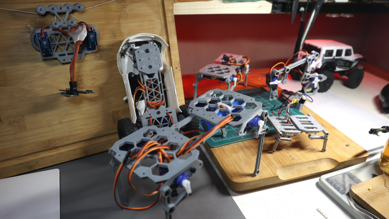
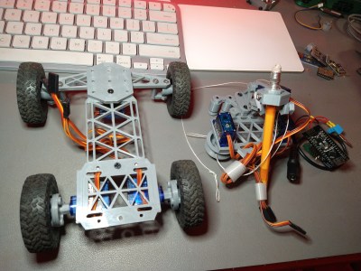
This Hackaday prize entry from [saul] is the beginning of a reconfigurable kit of 3D printed parts and servo motors for robotics learning. With just access to a printer, a few cheap-as-chips servo motors, an Arduino, and some nuts and bolts, you could be hacking together robot walkers within a few hours of starting!

Bolt Bots is very simple to understand, with all the mechanics and wiring out there in the breeze, but strictly for indoor use we reckon. If you want to add remote control to your application, then drop in one of the ubiquitous nRF24L01 boards and build yourself a copy of the remote control [saul] handily provides in this other project.

There really isn’t a great deal we can say about this, as it’s essentially a build kit with quite a few configuration options, and you just have to build with it and see what’s possible. We expect the number of parts to proliferate over time giving even more options. So far [saul] demonstrates a few flavors of ‘walkers’, a rudimentary ‘robot arm’, and even a hanging drawbot.

The bolt hardware can be found in this GitHub repo, and the remote control code in this second one.

Servo-based designs are sometimes sneered at due to their dubious accuracy and repeatability, but with a little of effort, this can be vastly improved upon. Also, multi-legged walkers need multiple servos and controllers to drive ’em. Or do they?

The HackadayPrize 2023 is Sponsored by:

Arduino Drum Platform Is Fast

Drums are an exciting instrument to learn to play, but often prohibitive if there are housemates or close neighbors involved. For that problem there are still electronic drums which can be played much more quietly, but then the problem becomes one of price. To solve at least part of that one, [Jeremy] turned to using an Arduino to build a drum module on his own, but he still had to solve yet a third problem: how to make the Arduino fast enough for the drums to sound natural.

Playing music in real life requires precise timing, so the choice of C++ as a language poses some problems as it’s not typically as fast as lower-level languages. It is much easier to work with though, and [Jeremy] explains this in great detail over a series of blog posts detailing his drum kit’s design. Some of the solutions to the software timing are made up for with the hardware on the specific Arduino he chose to use, including an even system, a speedy EEPROM, hardware timers, and an ADC that can sample at 150k samples per second.

With that being said, the hardware isn’t the only thing standing out on this build. [Jeremy] has released the source code on his GitHub page for those curious about the build, and is planning on releasing several more blog posts about the drum kit build in the near future as well. This isn’t the only path to electronic drums, though, as we’ve seen with this build which converts an analog drumset into a digital one.

Hack a Day 29 Jun 06:00

Review: OSEPP STEM Kit 1, a Beginner’s All-in-One Board Found in the Discount Aisle

As the name implies, the OSEP STEM board is an embedded project board primarily aimed at education. You use jumper wires to connect components and a visual block coding language to make it go.

I have fond memories of kits from companies like Radio Shack that had dozens of parts on a board, with spring terminals to connect them with jumper wires. Advertised with clickbait titles like “200 in 1”, you’d get a book showing how to wire the parts to make a radio, or an alarm, or a light blinker, or whatever.

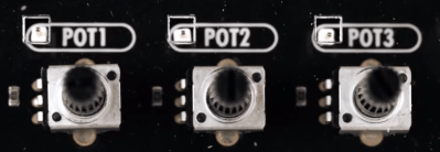
The STEM Kit 1 is sort of a modern arduino-powered version of these kits. The board hosts a stand-alone Arduino UNO clone (included with the kit) and also has a host of things you might want to hook to it. Things like the speakers and stepper motors have drivers on board so you can easily drive them from the arduino. You get a bunch of jumper wires to make the connections, too. Most things that need to be connected to something permanently (like ground) are prewired on the PCB. The other connections use a single pin. You can see this arrangement with the three rotary pots which have a single pin next to the label (“POT1”, etc.).
I’m a sucker for a sale, so when I saw a local store had OSEPP’s STEM board for about $30, I had to pick one up. The suggested price for these boards is $150, but most of the time I see them listed for about $100. At the deeply discounted price I couldn’t resist checking it out.

So does an embedded many-in-one project kit like this one live up to that legacy? I spent some time with the board. Bottom line, if you can find a deal on the price I think it’s worth it. At full price, perhaps not. Join me after the break as I walk through what the OSEPP has to offer.

What’s Onboard?
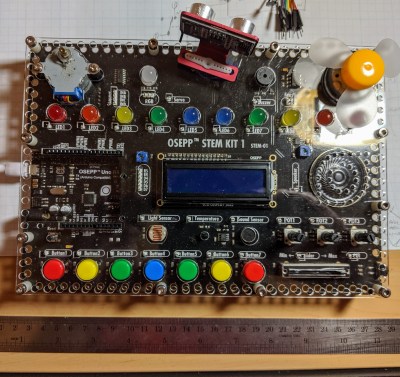
There are plenty of input and output devices:

  • 7 Push Buttons
  • Potentiometers (3 rotary and 1 slide)
  • Passive Infrared Sensor (PIR)
  • Light Sensor
  • Sound Sensor
  • LM35 Temperature Sensor
  • 10 LEDs (various colors)
  • Servo Motor
  • Stepper Motor
  • DC Motor
  • LCD Display
  • Buzzer
  • Speaker
  • RGB LED

In addition, the kit comes with an ultrasonic distance sensor in a little bracket that can connect to the stepper motor. That’s the only part that needs power and ground that isn’t already wired up.
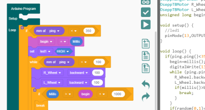
Because the heart of the board is an Arduino UNO clone, you can do anything you like to program it. However, OSEPP touts their visual block diagram language that is basically Scratch. You can use it for free on most platforms and there is even a Web-based version although it can’t download code. It looks like Scratch or other block-oriented systems you’ve seen before.

I’m not usually fond of the visual block languages, but this one at least shows you the actual Arduino code it generates, so that isn’t bad. But you can still use any other method you like such as the standard IDE or PlatformIO.

You can see a video about the board, below.

The Good and the Bad

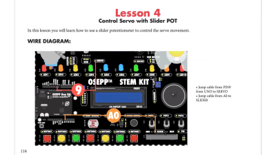
The board feels substantial and able to withstand a good bit of abuse. There’s a good range of components, and I like that the arduino is a real daughter board and not just built onto the PCB. Despite using the block language, I do like the tutorial booklet. It is very slick and has projects ranging from an IR doorbell to a mini piano. You can see a page below — very colorful and clear.
Of course, the suggested retail price of $150 is a bit offputting. You might think a breadboard with a handful of LEDs and other parts would be a much lower-cost option but just look around for arduino kits for beginners and you’ll find prices are all over the place. On the other hand, with a parts kit you would have to know how to wire up things like stepper motors or DC motors, so there is some value to having it already done for you. There’s also value in not having a bag of parts to misplace.

The jumper wires in the kit have pins on one side and sockets on the other. The pins go into the Arduino’s connector and the sockets go over pins on the components. These aren’t quite as reliable as a spring clip and not as versatile either.

In my mind the worst part of the kit design is that the pins are right next to each of the components. That’s good for understanding, but it makes a mess of wiring. For instance, there are ten LEDs, and connecting them all means stretching jumper wires to both edges of the board The jumpers aren’t very long either, so any complex project is going to have wires crisscrossing the sensors and LCD.
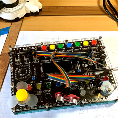
Granted, in this image I could have removed some of the wires from the bundles but that wouldn’t help that much, either. If you need to hook up more than a few of the available components you will have a mess. I would have put some sort of spring clip or even screw terminals and put them all on the top and bottom of the board with clear color-coded marking about where they connect. Then the wiring would all be out of the way. There are probably a few other ways they could have gone, and at this price, they could afford the few extra inches on the PCB.

There are a few other things that would have been nice touches to finish off this kit. I would have enjoyed a short chapter in the booklet about using the Arduino IDE directly so that people know it exists. And having even a small breadboard attached for your own exploration would make sense, but would then call for a different type of jumper wire.

Short Example Using the Distance Sensor

I wanted to do something with the board so I decided to play with the distance sensor and the servo. The distance sensor is a bit annoying both because you have to wire it all up and it has a tendency to fall off when you transport the board.

The demo (you can find it online) won’t win any originality prizes. The program moves the servo to scan from 0 to 180 degrees in 5 degree increments. It measures the distance of what’s in front of it. When it completes a scan, if it saw something close (you could adjust the sensitivity), it moves the sensor back to that position and waits 30 seconds. Otherwise, it keeps scanning.

Really, this is no different from any other Arduino program. That’s kind of the point. Despite the emphasis in the book on the point-and-click language, this is really just an Arduino.

In Summary

For the deep sale price I found, the board will work well for its intended audience of students or anyone starting out with Arduino or microcontrollers. Even a more advanced audience who just wants a way to hammer out a quick prototype might find it worth the $30 or $40 you can sometimes pay. But at full price, it is hard to imagine this makes sense because of the mess of wire routing and limited expansion options.
Build an automatic cat treat dispenser with Hummingbird

The Hummingbird by BirdBrain Technologies is an Arduino AtHeart microcontroller designed to enable beginners to create robots from craft materials. Hummingbird kits include LEDs, motors, and sensors that connect directly to the board. This eliminates the need for soldering or breadboarding and ensures that users have the parts they need to build their first robots. All of the components are reusable, so the same kit can be used to build many different robots.

In addition, the Hummingbird supports a variety of programming options, making it appropriate for beginning programmers as well as those who are more advanced. Some programming languages, such as Scratch and Snap!, can only be used when the board is connected to the computer. We will concentrate here on programming alternatives that enable users to upload a program onto the board’s Arduino.

Classrooms all over the world have used the Hummingbird from elementary to high school for projects ranging from Shakespeare dioramas to the physics of amusement park rides. In the following project, the BirdBrain Technologies team will show how they used the Hummingbird to build an automatic cat treat dispenser and demonstrate how the Hummingbird can be utilized to construct robots from everyday materials.

Building with the Hummingbird
Beginners can easily get started building Hummingbird robots with cardboard and craft materials. Motors, sensors, and LEDs can be connected directly to the Hummingbird board, and these elements can be added to the robot with hot glue. Hot glue peels off the components so that they can later be reused.

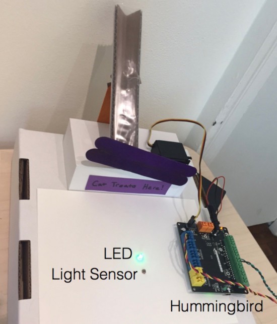
The example project uses one servo motor, one single color LED, and a light sensor. The dispenser consists of a servo motor attached to craft sticks that block the bottom of a chute containing cat treats. The position of the servo motor can be changed in software to release treats.

To receive a treat, the cat must cover a light sensor in front of the chute. When the cat covers the sensor, the servo motor briefly moves to open the chute and dispense a treat. The LED was included to show our test cat the location of the light sensor.

Programming with the Hummingbird
One unique feature of the Hummingbird is that it supports three different programming options for producing an Arduino program. These options provide steps of increasing difficulty to support learners as they transition from programming novices to Arduino experts.

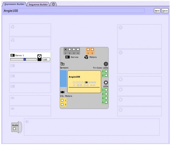
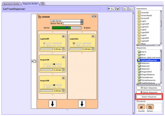
Beginners can start with the CREATE Lab Visual Programmer. This software option is based on storyboarding. Users can select the motors and LEDs that they are using on a schematic of the Hummingbird board. Then they can create expressions by using sliders to set the values of these outputs. The expression below sets a servo motor to 100°.

Expressions can be combined to create sequences. For example, the sequence below controls our automatic cat treat dispenser. This sequence is controlled by a sensor block. If the light level is low, the three expressions on the left are executed. If the light level is high, the three expressions on the right are executed. The user can then convert this sequence to an Arduino program by simply clicking the “Export Sequence” button (shown outlined in red). The Hummingbird can then be placed into Arduino mode and the program uploaded to the microcontroller.

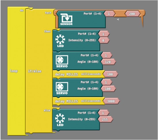
Another option for beginners is ArduBlock, which provides a visual introduction to the Arduino language. The Hummingbird extension for ArduBlock includes a block for each Hummingbird component. A program in ArduBlock to control the treat dispenser is shown below. This program is equivalent to the CREATE Lab Visual Programmer sequence shown above.

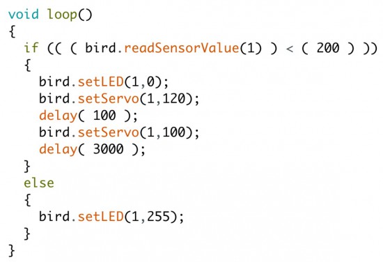
The Arduino code generated by this ArduBlock program is shown below. Individuals moving from the CREATE Lab Visual Programmer or ArduBlock to Arduino can start by modifying the generated code. For example, in the video we modified the commands inside the else to make the LED blink to attract the cat’s attention.

Once individuals are comfortable with the Arduino programming language, they can create more complex programs in Arduino. For instance, the video shows how we modified our robot and our code to incorporate three lights and three sensors. To get a treat, the cat must cover the sensor when the corresponding light is on.

The cat treat dispenser is only one example of a Hummingbird robot using the power of the Arduino at its core. The parts can be used and reused to construct an unlimited number of robots with low-cost materials such as cardboard, pipe cleaners, recycled materials, and even paper mache!

Add Robotic Farming to Your Backyard with Farmbot Genesis

Growing your own food is a fun hobby and generally as rewarding as people say it is. However, it does have its quirks and it definitely equires quite the time input. That’s why it was so satisfying to watch Farmbot push a weed underground. Take that!

Farmbot is a project that has been going on for a few years now, it was a semifinalist in the Hackaday Prize 2014, and that development time shows in the project documented on their website. The robot can plant, water, analyze, and weed a garden filled with arbitrarily chosen plant life. It’s low power and low maintenance. On top of that, every single bit is documented on their website. It’s really well done and thorough. They are gearing up to sell kits, but if you want it now; just do it yourself.

The bot itself is exactly what you’d expect if you were to pick out the cheapest most accessible way to build a robot: aluminum extrusions, plate metal, and 3D printer parts make up the frame. The brain is a Raspberry Pi hooked to its regular companion, an Arduino. On top of all this is a fairly comprehensive software stack.

The user can lay out the garden graphically. They can get as macro or micro as they’d like about the routines the robot uses. The robot will happily come to life in intervals and manage a garden. They hope that by selling kits they’ll interest a whole slew of hackers who can contribute back to the problem of small scale robotic farming.


Filed under: cnc hacks, green hacks

the easiest educational robot for kids, Mbot, goes AtHeart

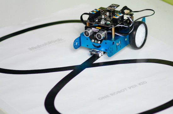
It’s cute, it’s fun and easy to assemble, it’s mBot by Makebloc, the new educational robot joining Arduino AtHeart program!

mBot it’s an all-in-one solution for kids and beginners to enjoy the hands-on experience about robotics, programming, and electronics.

You can program it with drag-and-drop graphical programming software based on Scratch 2.0 and the magic happens: the robots can follow lines, kick balls and push objects, avoid walls and more. You can also switch from graphical to text-based programming in Arduino mode as it can be coded with Arduino IDE environment.

Watch the video of their successful Kickstarter campaign:

mBot supports wireless communication, standard Arduino boards like Arduino Uno, Leonardo boards, Arduino Nano, Arduino Mega 2560, Makeblock mCore (based on Arduino Uno).

The main control board’s design, mCore of mBot, is based on Arduino UNO: with intuitional color labels and easy-to-use RJ25 connectors, the board can get wired easily so students can then get more time to focus on creating all kinds of interactive stories and projects.

To help teachers, parents, and kids get started easier and faster the robot kit has two free tutorial e-books and online manuals are provided and increasing continually.

Take a look at mBot on Makeblock website and discover how to use 2.4GHz wireless module and Bluetooth module with mBot:

Arduino Blog 30 Nov 15:15

A DIY smartwatch designed by a kid for kids

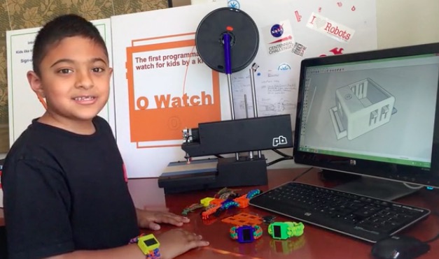
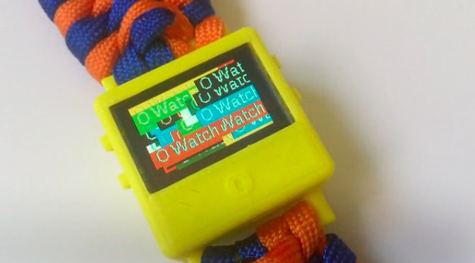
Omkar is a special 8 years old who created a wearable device called O Watch: an Arduino Zero-based smartwatch kit for kids. The project, recently kickstarted, allows young people to learn programming, 3D printing and a bit of craft while making their own smartwatch and customizing it. The kit will be released with a series learning tools including a kid-friendly website with easy tutorials, examples and a community to share creations.

He’s not new to DIY tech and learning as he’s been doing a few workshops to teach Arduino to other kids and likes it when they get excited about making Arduino projects. Omkar told us:

I was first interested in robots. But my dad got me started with projects that light up LEDs that were easier to learn and code myself. (ps: my dad did not let me get a robot kit at first :).

I decided to do a wearable project because there were many of them I saw in the news and I thought they were cool. I wanted to make a smartwatch so that I could wear it myself and share my project with my friends in school.

If you are a kid and are new to making, O Watch could be a great starting point as you’ll learn about coding, 3d printing, craft and also sharing. The Arduino IDE will be your  primary programming tool for the watch, the case can be 3D printed in a color of your choice and you’ll experiment on how to knot yourself a cool band to wear it.

What are you waiting for? You have just a few days to back the project on Kickstarter and have an O Watch delivered to your home!

Arduino Blog 08 Sep 23:03

Autodesk teams up with Arduino to electrify creativity and coding

We are excited to introduce our new collaboration with Autodesk, launching with us the Arduino Basic Kit in the US! Starting today we are bringing creativity and electronics to everyone wanting to get started with more than 30 components added into the 123D Circuits simulator and 15 step-by-step tutorials available through the Project Ignite learning platform.

With the Arduino Basic Kit you’ll be able to access digital simulations for a unique experience of engagement with the kit, understanding and tapping right away into the power of smart objects.

“Arduino is creating new opportunities for makers and educators to get hands on with coding and electronics,” said Samir Hanna, vice president and general manager, Consumer and 3D Printing, Autodesk. “Our collaboration with Arduino will enable our passionate community of users to unlock their creativity while building the skills to succeed in a technologically-focused world.”

“By collaborating with Autodesk on the Arduino Basic Kit we are showing that designing electronics is a great educational area for teachers,” said Massimo Banzi, co-founder of Arduino. “By offering our tutorials in digital format instructors can involve students of all ages on interactive projects within Project Ignite platform.”

Autodesk recently launched Project Ignite during the White House National Week of Making to provide a free and open learning platform that builds the skills of young learners through creative, hands-on design experiences focused on the latest technology trends like 3D printing and electronics. Through these efforts, Autodesk aims to empower the next generation of innovators with the tools and confidently enter this new future of making things.


What’s in the Arduino Basic Kit:

  • All the physical and digital components you need to build simple projects and learn how to turn an idea into reality using Arduino and Autodesk 123D Circuits.
  • The digital simulations in 123D Circuits provide a unique experience to engage and learn about the power of smart objects .
  • Exclusive online access to 15 step-by-step tutorials, through the Project Ignite learning platform, to make simple projects using components that let you control the physical world.

Projects include:

  • Get to know your tools: An introduction to the concepts you need to know to advance
  • Love-O-Meter to measure how hot-blooded you are
  • Zoetrope to create a mechanical animation you can play forward or reverse
  • Knock Lock to tap a secret code and open the door

Get your kit today, exclusively at www.autodesk.com/arduino for $84.00.

Join the conversation on the Arduino Forum.


Solderless Noise-o-Tron Kit Makes Noise at Chicago Makerfaire

Anyone who’s manned a hackerspace booth at an event knows how difficult it can be to describe to people what a hackerspace is. No matter what words you use to describe it, nothing really seems to do it justice. You simply can’t use words to make someone feel that sense of accomplishment and fun that you get when you learn something new and build something that actually works.

[Derek] had this same problem and decided to do something about it. He realized that in order to really share the experience of a hackerspace, he would have to bring a piece of the hackerspace to the people.  That meant getting people to build something simple, but fun. [Derek's] design had to be easy enough for anyone to put together, and inexpensive enough that it can be produced in moderate quantities without breaking the bank.

[Derek] ended up building a simple “optical theremin”. The heart of this simple circuit is an ATTiny45. Arduino libraries have already been ported to this chip, so all [Derek] had to do was write a few simple lines of code and he was up and running. The chip is connected to a photocell so the pitch will vary with the amount of light that reaches the cell. The user can then change the pitch by moving their hand closer or further away, achieving a similar effect to a theremin.

[Derek] designed a simple “pcb” out of acrylic, with laser cut holes for all of the components. If you don’t have access to a laser cutter to cut the acrylic sheets, you could always build your own. The electronic components are placed into the holes and the leads are simply twisted together. This allows even an inexperienced builder to complete the project in just five to ten minutes with no complicated tools. The end result of his hard work was a crowded booth at a lot of happy new makers. All of [Derek's] plans are available on github, and he hopes his project will find use at Makerfaires and hackerspace events all over the world.


Filed under: ATtiny Hacks, Hackerspaces

Project Review – Silicon Chip Capacitance Substitution Box

Introduction

Every month Australian electronics magazine Silicon Chip publishes a variety of projects, and in some cases various (well … one of two) electronics retailers will pick up the project and offer it as a kit. However for an increasing number of new projects they don’t, which leaves the interested reader with one option – build the entire project from scratch.

But thankfully this is no longer the case – as the team from Silicon Chip now offer a range of project PCBs and matching front panels for sale directly from their website. Although buying these parts is not the cheapest option, it gives the busy person who likes making things a quick start – or the inexperienced more opportunities to complete a successful project.

So as a test of this new service, I bought the PCB and front panel for the Capacitance Substitution Box project described by Nicholas Vinen in the Juily 2012 issue of SC:

This is something I’ve meant to make for a while – but didn’t really have the inclination to make one from scratch, so it was neat to see a version published in the magazine. I believe the subjects in the magazine article are oftern prototypes, which explains the difference in colour for the front panel.

The parts arrived in a week after placing the order, and are of a high quality:

When complete, the capacitance substitution box PCB and panel will fit nicely into an Altronics H0151 enclosure, so you don’t need to do any drilling or filing. The next task was to organise the required parts. The rotary switches, terminal posts and the usual odds and ends can be found at Altronics, Jaycar or other suppliers. However the main components – the capacitors – offered two options.

The first option is to simply use capacitors from personal stock or the stores. However the tolerance of these parts can vary wildly, with up to twenty percent either way. This is ok for simple uses, however when values are combined – the tolerance of larger values can negate the lower values completely. So instead I’ve chosen the second option – which involves using brand-name low-tolerance capacitors.

Thus I turned to element14 who stock not only a huge range of not only regular but also the low-tolerance capacitors, and can also have them on my desk usually by the next working day. Finally, it’s nice to have all the parts arrive in little bags… neatly organised ready to go:

It’s easy to search for low-tolerance parts with element14, as the automatic filtering has tolerance as a parameter:

Furthermore you can also ensure you have the voltage rating of at least 50V DC as well. So after half an hour the capacitor order was completed and arrived when expected – using parts from Panasonic, Vishay, and Wima. The tolerances of our capacitors used varied between one and ten percent, which will help improve the accuracy of the substitution box.

Assembly

The PCB has the capacitor values labelled neatly on the silk-screen, so soldering in all the capacitors was a relatively simple but long operation. Having them arrive in separate packets made life a lot easier. During the soldering process it’s a good idea to have a  break or two, which helps you avoid fatigue and making any mistakes.

There may be a few capacitors that are a little too wide to fit with the others, so they can be mounted on the other side of the PCB:

However they all end up fitting well:

The next step was to configure the first rotary switch for six position use, then cut the plastic stopped from the side of each rotary switch. In the following image you have a before and after example:

Now the rotary switches can have their shafts trimmed and then be soldered onto the PCB:

However ensure you have the first rotary switch in the right way – that is the selections are selected across the top half, not the bottom. Remove the nuts from the rotary switches, and double-check all the capacitors are fitted, as once the next step is completed … going back will be difficult to say the least.

At this point the banana sockets can be fitted to the panel, and then soldered into place, and then you’re finished. Just place the panel/PCB combination inside the box and screw it down:

Using the Capacitance Substitution Box

Does it work? Yes – however you don’t get exact values, there will always be a tolerance due to the original tolerance of the capacitors used and the stray capacitance of the wires between the box and the circuit (or capacitance meter). Nevertheless our example was quite successful. You can see the box in action with our Altronics LC meter kit in this video.

Again, using the best tolerance capacitors you can afford will increase the accuracy of this project.

Conclusion

Over time this would be a useful piece of equipment to have – so if your experiments or projects require varying capacitor value, this project will serve the purpose nicely. Plus it helps with mental arithmetic and measures of capacitance! Please do not ask me for copies of the entire Silicon Chip article, refusal may offend. Instead – visit their website for a reprint or digital access.

And if you enjoyed this article, or want to introduce someone else to the interesting world of Arduino – check out my book (now in a third printing!) “Arduino Workshop”.

Have fun and keep checking into tronixstuff.com. Why not follow things on twitterGoogle+, subscribe  for email updates or RSS using the links on the right-hand column, or join our forum – dedicated to the projects and related items on this website. Sign up – it’s free, helpful to each other –  and we can all learn something.

The post Project Review – Silicon Chip Capacitance Substitution Box appeared first on tronixstuff.