Prextron CHAIN BLOCKS - Arduino Nano controlled Ultrasonic sensor that switches a motor wirelessly using 433MHz RF modules and a relay board.
Description
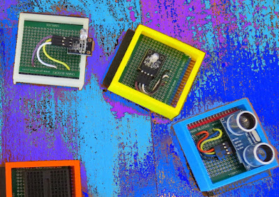
In this tutorial, I will be evaluating Prextron CHAIN blocks – a new system that allows you to connect your sensors and actuators to an Arduino NANO using clever 3D-printed prototyping boards that can be stacked sideways. This very modular system makes it easy to connect, disconnect and replace project components, and eliminate the “rats nest of wires” common to many advanced Arduino projects. CHAIN BLOCKS are open, which means that you can incorporate any of your sensors or actuators to these prototyping boards, and you can decide which specific pin on Arduino you plan to use. The CHAIN BLOCK connections prevent or reduce common connection mistakes, which make them ideal for class-room projects and learning activities.
I am going to set up a project to put these CHAIN BLOCKs to the test:
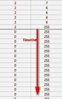
When I place my hand in-front of an Ultrasonic sensor, the Arduino will transmit a signal wirelessly to another Arduino, and consequently turn on a motor.
Parts Required:
You need the following Prextron Chain Blocks
- Arduino Nano x2
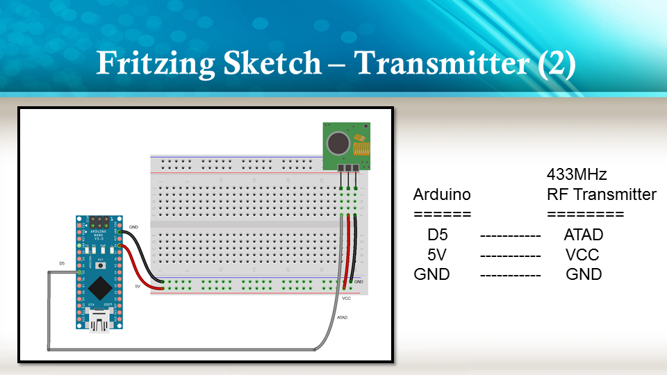
- 433MHz RF Transmitter and Receiver modules
- HC-SR04 Ultrasonic sensor
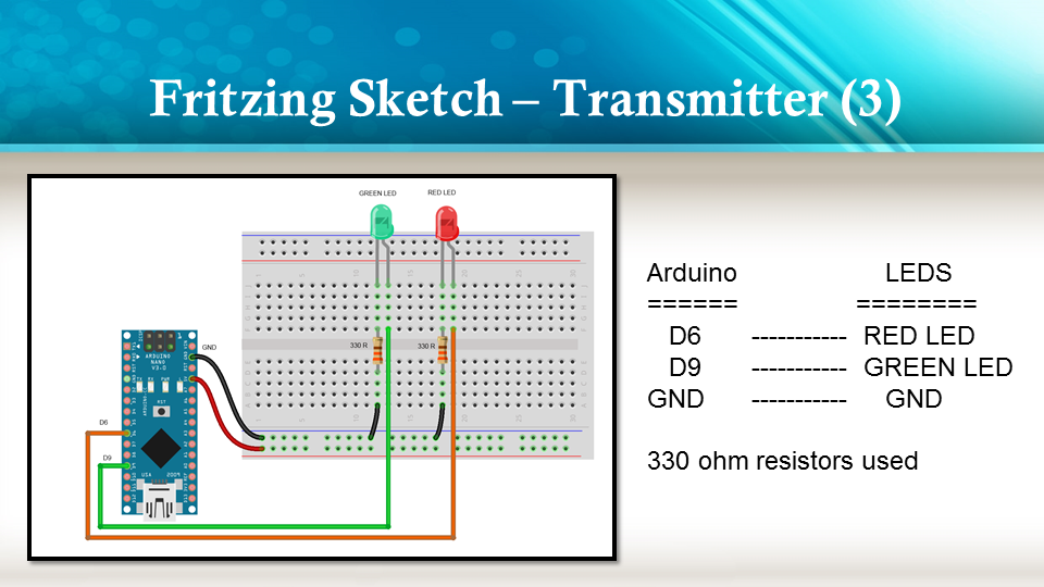
- RGB LED module
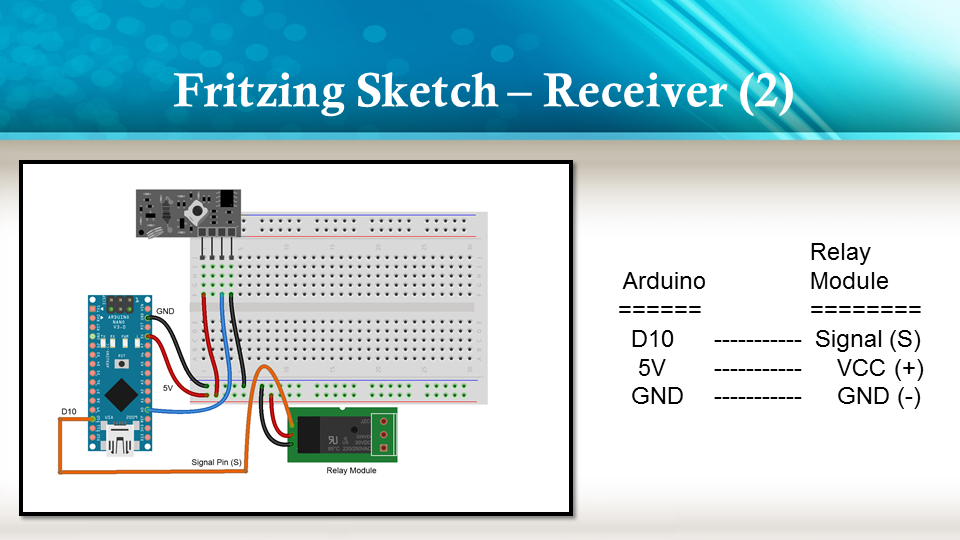
- Relay Module
- DC motor
- 9V battery
- 9V battery adapter
You also need a few extra components:
Please note: You may need to solder the module wires to the CHAIN BLOCK protoboard.
Arduino Libraries and IDE
This project does not use any libraries. However, you will need to upload Arduino code to the Arduino. For this you will need the Arduino IDE which can be obtained from the official Arduino website:
https://www.arduino.cc/en/main/software
ARDUINO CODE: RF Transmitter
ARDUINO CODE: RF Receiver
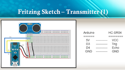
Fritzing diagrams for Transmitter
![]()
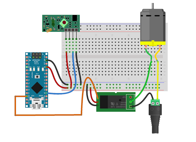
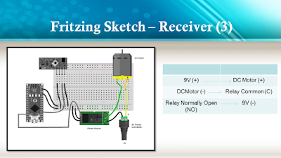
Fritzing diagrams for Receiver

Concluding comments
The purpose of this project was to evaluate Prextron CHAIN BLOCKs and put them to the test. Here is what I thought of CHAIN BLOCKS at the time of evaluation. Some of my points mentioned below may no longer apply to the current product. It may have evolved / improved since then. So please take that into consideration
What I liked about Chain Blocks
- The design is simple, the product is simple.
- Once the Chain Blocks were all assembled, they were very easy to connect to each other.
- I can really see the benefit of Chain Blocks in a teaching environment, because it simplifies the connection process, and reduces connection mixups.
- It was good to see that the blocks come in different colours, which means that you can set up different colour schemes for different types of modules.
- You can incorporate pretty much any sensor or Actuator into the Chain block which is very appealing.
- You also have the flexibility of choosing which pins you plan to use on the Arduino.
- Projects look a lot neater, because you no longer have the rats nest of wires.
- The Blocks lock into each other which means that they are much easier to transport/carry.
What I did not like about Chain Blocks
- In most cases, the Chain Block protoboard lanes were not numbered, which increased the chances of making mistakes when soldering
- The need to solder modules to the protoboard, may be a discouragement for some people.
- I would have liked a choice of different size Chain blocks. Some of the sensors did not fit nicely into the Square blocks.
- Prextron really need to work on their website if they plan to get serious with this product: Webpage has incomplete functionality or irrelevant links etc etc.
Thank you very much to Prextron for providing the CHAIN BLOCKS used in this tutorial, and allowing me to try out their product. If you are interested in trying them yourself, then make sure to visit them at:
Visit my ArduinoBasics Google + page.
Follow me on Twitter by looking for ScottC @ArduinoBasics.
I can also be found on Pinterest and Instagram.
Have a look at my videos on my YouTube channel.