Posts with «binary» label

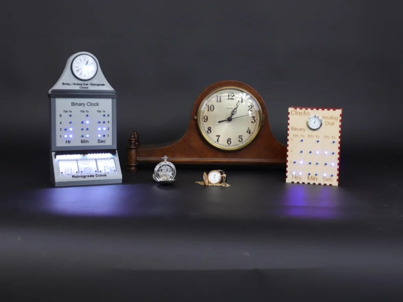
Clock Mixes Analog, Digital, Retrograde Displays

Unique clocks are a mainstay around here, and while plenty are “human readable” without any instruction, there are a few that take a bit of practice before someone can glean the current time from them. Word clocks are perhaps on the easier side of non-traditional displays but at the other end are binary clocks or even things like QR code clocks. To get the best of both worlds, though, multiple clock faces can be combined into one large display like this clock build from [imitche3].

The clock is actually three clocks in one. The first was inspired by a binary clock originally found in a kit, which has separate binary “digits” for hour, minute, and second and retains the MAX 7219 LED controller driving the display. A standard analog clock rests at the top, and a third clock called a retrograde clock sits at the bottom with three voltmeters that read out the time in steps. Everything is controlled by an Arduino Nano with the reliable DS3231 keeping track of time. The case can be laser-cut or 3D printed and [imitche3] has provided schematics for both options.

As far as clocks builds go, we always appreciate something which can be used to tell the time without needing any legends, codes, or specialized knowledge. Of course, if you want to take a more complex or difficult clock face some of the ones we’re partial to are this QR code clock which needs a piece of hardware to tell the time that probably already has its own clock on it.

8 Crazy Keyboards That Will Trick Out Your Typing

A custom keyboard could be right at your fingertips, so why are you still using that basic keyboard that came with your computer?

Read more on MAKE

The post 8 Crazy Keyboards That Will Trick Out Your Typing appeared first on Make: DIY Projects and Ideas for Makers.

Binary Clock Fit For Queen Elsa’s Ice palace

When life gives you lemons, you make lemonade. When life gives you freezing cold temperatures and a yard full of snow, you make binary clocks out of ice. At least that’s what [Dennis] does, anyway.

[Dennis’] clock is made from several cylindrical blocks of ice stacked on top of one another. There are six columns of ice blocks. The blocks were made by pouring water into empty margarine containers and freezing them. Once they were frozen, [Dennis] bore a 5/16″ hole into the bottom of each block to house an LED. Wires ran from the LEDs back into the drainage port of a cooler.

The cooler housed the main electronics. The LED controller board is of [Dennis’] own design. It contains six TLC59282 chips allowing for control of up to 96 LEDs. Each chip has its output lines running to two RJ45 connectors. [Dennis] couldn’t just use one because one of the eight wires in the connector was used as a common power line. The main CPU is an Arduino. It’s hooked up to a DS3234 Real Time Clock in order to keep accurate time. The oscillator monitors temperature in order to keep accurate time even in the dead of winter.


Filed under: Arduino Hacks, led hacks

Binary Clock Would Make Doc Brown Proud

[Brett] was looking for a way to improve on an old binary clock project from 1996. His original clock used green LEDs to denote between a one or a zero. If the LED was lit up, that indicated a one. The problem was that the LEDs were too dim to be able to read them accurately from afar. He’s been wanting to improve on his project using seven segment displays, but until recently it has been cost prohibitive.

[Brett] wanted his new project to use 24 seven segment displays. Three rows of eight displays. To build something like this from basic components would require the ability to switch many different LEDs for each of the seven segment displays. [Brett] instead decided to make things easier by using seven segment display modules available from Tindie. These modules each contain eight displays and are controllable via a single serial line.

The clock’s brain is an ATmega328 running Arduino. The controller keeps accurate time using a DCF77 receiver module and a DCF77 Arduino library. The clock comes with three display modes. [Brett] didn’t want and physical buttons on his beautiful new clock, so he opted to use remote control instead. The Arduino is connected to a 433MHz receiver, which came paired with a small remote. Now [Brett] can change display modes using a remote control.

A secondary monochrome LCD display is used to display debugging information. It displays the time and date in a more easily readable format, as well as time sync information, signal quality, and other useful information. The whole thing is housed in a sleek black case, giving it a professional look.


Filed under: Arduino Hacks
Hack a Day 09 Jan 03:00

Kit Review – Maniacal Labs Epoch Clock

Introduction

The subject of our latest kit review is the “Epoch Clock” from Maniacal Labs, a new organisation started by three young lads with some interesting ideas. Regular readers will know we love a clock – so when the opportunity came to review this one, we couldn’t say no.

At this point you may be thinking “what is Epoch time anyway?”. Good question! It is the number of seconds elapsed since the first of January, 1970 (UTC) – and used by Unix-based computers as the start of their time universe. (For more on the theory of Epoch time, check out Wikipedia). For example – 1379226077 Epoch time is Sun, 15 Sep 2013 06:21:17 GMT. That’s a lot of seconds. If you’re curious, you can do more calculations with the EpochTime website.

Moving forward, this clock kit will show Epoch time in full 32-bit binary glory, using a DS1307 real-time clock IC (with backup battery) and is controlled with an ATmega328P-PU – so you can modify the code easily with the Arduino IDE or WinAVR (etc).

Assembly

The creators have spent a lot of time on not only the packaging and out-of-box-experience, but also the documentation and setup guide – so as long as you’re fine with simple through-hole soldering the kit will not present any challenges. The kit arrives in a sturdy box:

… with well packaged components. Everything is included for the finished product, as well as IC sockets, the RTC backup battery and a USB cable so you can power the clock from a USB hub:

The PCB is a good thickness, and has a clear silk-screen and solder mask:

Construction is simple, just follow the step-by-step instructions. Starting with the USB socket for power:

… then the resistors:

… the LEDs:

… all 32 of them. Note that the LEDs don’t sit flush with the PCB, so a little effort is required to keep them aligned:

 Then the rest of the components just fit as expected. I’ve also added the included header pins for an FTDI programming cable and ICSP to keep my options open:

Then simply fit the battery, insert the ICs and you’re done:

Using the clock

The microcontroller is pre-programmed, so you can use the clock straight away. You will however need to set the time first. To make this incredibly easy, there is a special web page that displays the current time and Epoch time, which steps you through the process of setting the time using the buttons.

Or with some code available on the kit github page and a programming cable, you can automatically sync it to the clock. Once setup, the battery will keep the current time in the RTC nicely. The clock is powered by 5V, which is easily supplied with the included USB cable, or you can always hack in your own feed.

So what does Epoch time in 32-bit binary look like? Here’s a short video of the clock in action:

Reading the time requires converting the binary number displayed with the LEDs back to a decimal number – which is of course the Epoch count of seconds since 1/1/1970. Math teachers will love this thing.

But wait, there’s more!

If you get tired of the blinking, there’s a test function which is enabled by holding down both buttons for a second, which turns the Epoch Clock into a nifty Larson Scanner:

To create your own sketches or examine the design files in more detail, it’s all on the clock github page. From a hardware perspective you have an ATmega328P-PU development board with a DS1307 battery-backed real-time clock – with 32 LEDs. So you could also create your own kind of clock or other multi-LED blinking project without too much effort. Review the EpochClockSchematic (.pdf) to examine this in more detail.

Conclusion

I really enjoyed this kit – it was easy to assemble, I learned something new and frankly the blinking LEDs can be quite soothing. The clock would make a great for a conversation-starter in the office, or would make an ideal gift for any Sheldon Cooper-types you might be associated with. Or have competitions to see who can convert the display to normal time. After shots.

Nevertheless it’s a fun and imaginative piece of kit, fully Open Hardware-compliant – and if you’ve made it this far – get some and have fun. Full-sized images are on flickr. Interested in Arduino? Check out my new book “Arduino Workshop” from No Starch Press.

In the meanwhile have fun and keep checking into tronixstuff.com. Why not follow things on twitterGoogle+, subscribe  for email updates or RSS using the links on the right-hand column? And join our friendly Google Group – dedicated to the projects and related items on this website. Sign up – it’s free, helpful to each other –  and we can all learn something.

[Note – The kit reviewed was a promotional consideration from Maniacal Labs]

The post Kit Review – Maniacal Labs Epoch Clock appeared first on tronixstuff.
Tronixstuff 15 Sep 10:29

3D Printed Binary Clock

Let's Make Robots 03 Aug 21:43
2  3d  3mm  arduino  binary  clock  cube  inches  ldr  powered  print  printed  teensy  usb