Posts with «projects» label

Project – Fun with Arduino-controlled Traffic Lights

The goal of this project is to make a pair of traffic lights that can be used for learning about Arduino digital inputs and outputs – or as the prototype for your own traffic lights in model layouts such as trains, dioramas, LEGO and so on. 

Imagine a two-way road that has a single-lane bridge – cars can only travel in one direction at a time. You need to build a system to stop drivers being impatient and risking their lives by approaching the bridge from both sides at the same time. 

Your solution is a set of traffic lights. One set at each end of the bridge – east and west, and a sensor to detect cars approaching the lights. We’ll use our traffic light and button modules to keep things simple:

When a car approaches one side – and the lights are red, the car must wait until the light changes. The sensor detects the car and the system changes the lights at the other end from green to yellow to red.

Then the lights at the other side hold red and flash yellow, to give the awaiting motorists a little notice before crossing the bridge – which they can do when the lights change to green. And vice-versa! So let’s get started.

Parts List

We use the tactile button boards as they are the equivalent to a button circuit with a 10k pull-down resistor; and we use the traffic lights as they are the equivalent of three LEDs with current-limiting resistors… that are much more convenient.

Putting it all together

Thanks to the modules we’re using, the whole system is plug-and-play. The following image is our example in action. But don’t panic – we’ll go through it step-by-step.

First we’ll connect the traffic lights. When you look at the bottom, you can see the pinout labels as such:

We’ll call this the east side. Plug the traffic light module into a solderless breadboard, with the pins across the numerical columns as shown in the final image. Then connect four jumper wires from the solderless breadboard columns matching R Y G GND to the Arduino’s D11, D10, D9 and GND respectively. 

Repeat this with another solderless breadboard (we’ll call it the west side) – connect four more jumper wires from the solderless breadboard columns matching R Y G GND to the Arduino’s D4, D3, D2 and GND respectively.

Now for the buttons. They have three pins – 5V, OUT and GND. When the button is pressed, the OUT pin goes from LOW to HIGH:

First, run a jumper wire from the 5V on the Arduino to a blank column on one solderless breadboard. Then run another wire from that column over to the the other solderless breadboard. This gives you 5V on both breadboards.

Next, on each breadboard, run a jumper wire from the traffic lights’ GND pin column to a column next to your 5V column on the breadboard. This gives you 5V and GND on each breadboard. 

To connect the west button – connect 5V and GND to the new spots on the solderless breadboard, and the OUT pin to Arduino D5. 

And for the east button – connect 5V and GND to the new spots on the solderless breadboard, and the OUT pin to Arduino D12. 

Now go back and double-check your wiring – once you’re satisfied it’s time to upload the sketch. 

The Arduino sketch

Time for the brains of the operation. Copy the sketch below and upload to your Arduino:

This file contains hidden or bidirectional Unicode text that may be interpreted or compiled differently than what appears below. To review, open the file in an editor that reveals hidden Unicode characters. Learn more about bidirectional Unicode characters
// https://tronixstuff.com/2025/04/15/project-arduino-controlled-traffic-lights/
//
// define the I/O pins that are used on the Arduino
// … the buttons
#define westButton 5
#define eastButton 12
// the LEDs on the traffic light modules
#define westRed 4
#define westYellow 3
#define westGreen 2
#define eastRed 11
#define eastYellow 10
#define eastGreen 9
#define yellowBlinkTime 500 // 0.5 seconds for yellow light blink
boolean trafficWest = true; // west = true, east = false
int flowTime = 5000; // amount of time to let traffic flow
int changeDelay = 2000; // amount of time between color changes
void setup()
{
// this code runs when the Arduino first powers-up
// or after a reset
// setup digital I/O pins
// buttons are INPUTs
pinMode(westButton, INPUT);
pinMode(eastButton, INPUT);
// LEDs are OUTPUTs
pinMode(westRed, OUTPUT);
pinMode(westYellow, OUTPUT);
pinMode(westGreen, OUTPUT);
pinMode(eastRed, OUTPUT);
pinMode(eastYellow, OUTPUT);
pinMode(eastGreen, OUTPUT);
// set initial state for lights – west side is green first
digitalWrite(westRed, LOW);
digitalWrite(westYellow, LOW);
digitalWrite(westGreen, HIGH);
digitalWrite(eastRed, HIGH);
digitalWrite(eastYellow, LOW);
digitalWrite(eastGreen, LOW);
}
void loop()
// this code runs continuously until power-off or a reset
{
if ( digitalRead(westButton) == HIGH )
// request west to east traffic flow
{
if ( trafficWest != true )
// only continue if traffic flowing in the opposite (east) direction
{
trafficWest = true; // change traffic flow flag to west>east
delay(flowTime); // give time for traffic to clear the bridge
digitalWrite(eastGreen, LOW); // change east-facing lights from green…
// to yellow to red
digitalWrite(eastYellow, HIGH);
delay(changeDelay);
digitalWrite(eastYellow, LOW);
digitalWrite(eastRed, HIGH);
delay(changeDelay);
for ( int a = 0; a < 5; a++ ) // blink yellow light
{
digitalWrite(westYellow, LOW);
delay(yellowBlinkTime);
digitalWrite(westYellow, HIGH);
delay(yellowBlinkTime);
}
digitalWrite(westYellow, LOW);
digitalWrite(westRed, LOW); // change west-facing lights from red to green
digitalWrite(westGreen, HIGH);
}
}
if ( digitalRead(eastButton) == HIGH ) // request east to west traffic flow
{
if ( trafficWest == true )
// only continue if traffic flow is in the opposite (west) direction
{
trafficWest = false; // change traffic flow flag to east>west
delay(flowTime); // give time for traffic to clear the bridge
digitalWrite(westGreen, LOW);
// change west lights from green to yellow to red
digitalWrite(westYellow, HIGH);
delay(changeDelay);
digitalWrite(westYellow, LOW);
digitalWrite(westRed, HIGH);
delay(changeDelay);
for ( int a = 0 ; a < 5 ; a++ ) // blink yellow light
{
digitalWrite(eastYellow, LOW);
delay(yellowBlinkTime);
digitalWrite(eastYellow, HIGH);
delay(yellowBlinkTime);
}
digitalWrite(eastYellow, LOW);
digitalWrite(eastRed, LOW); // change east-facing lights from red to green
digitalWrite(eastGreen, HIGH);
}
}
}
view raw traffic.ino hosted with ❤ by GitHub

You can now operate your traffic lights! If you are facing the red light, press the matching button and wait until the lights change before you can cross the bridge.

You can adjust the delays, the speed of light-changing and the other aspects in the sketch. In some countries you may not have flashing yellow before green – so you could remove that feature.

You can see our example in operation from the video below:

Where to from here? 

You can now understand how the basic inputs and outputs of an Arduino development board can be harnessed for fun and useful projects. You could expand on this system by adding more traffic lights and buttons – use an Arduino Mega-compatible board as it has plenty more inputs and outputs.

Or you could experiment by using different types of sensors instead of buttons – such as motion detectors, beam-break switches or something home-made.

I hope you had fun with the traffic lights, or at least enjoyed reading about the blinking fun. To keep up to date with new posts at tronixstuff.com, please subscribe to the mailing list in the box on the right, or follow us on x – @tronixstuff.

If you find this sort of thing interesting, please consider ordering one or more of my books from amazon:

Tronixstuff 15 Apr 04:24

A DIY Arduino Nixie tube clock

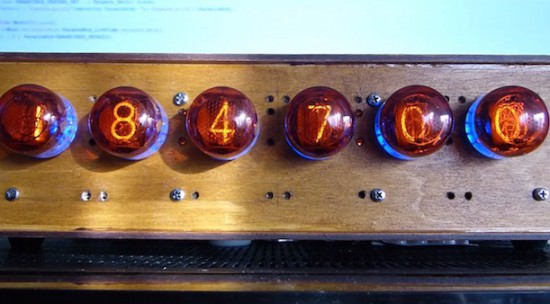
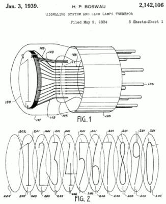
Nixie tubes have a lot of fans because of their retro style. They are neon valve tubes, where 10 cathodes shaped like numbers from 0 to 9 are switched on by plasma when high voltage flows through them. Patented in the 1930s by H.P. Boswau, they were wildly popular in the ‘60s and remained so until LEDs became cheaper to manufacture in the ‘70s. Many Makers today are creating vintage-look clocks using, now rare, Nixies bought on eBay with the help of an Arduino or Genuino Uno to control them.

In the video below, Jozsef Kovecses built a Nixie clock with NTP time syncronization using a Genuino Uno, a Geeetech IduinoShield, DS1307 RTC, DC-to-DC converter, and Nixie tube modules to drive the tubes directly.

Arduino Blog 15 Jun 11:55

Submit or import your project on Project Hub

The Arduino Project Hub (powered by Hackster.io) is a community dedicated to discovering how fun and rewarding tinkering with electronics and software can be, so any project made with Arduino and Genuino boards is welcome! Each day, the Arduino Team will select some of the best tutorials and highlight them on our social channels.

The Arduino Project Hub is also a great place to keep your latest projects and easily share them with your friends, students and the rest of the community!

If you have tutorials and articles on other platforms, we’ve got some good news! There is a cool import function so you can just paste the link and we’ll take care of the transfer. When you click on ‘New Project’ you will be presented with two options, create a tutorial from scratch or import one via URL.

Read this tutorial to learn more.

Use Fair speaker and donate to musicians!


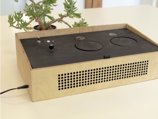
Most of the music we listen to comes from convenient streaming services distributing music of thousands of artists from all over the world.  But only a small amount of money actually reaches the artists you like. A team of student (Nicolas Armand, Inês Araújo, Mette Mørch, Monika Seyfried)  used a MKR1000  to implement a donation service during the Interaction Design Programme at CIID with the support of Massimo Banzi and Dario Buzzini:

We wanted to bring some awareness to this issue with our project. So, with this in mind we envisioned Fair Speaker, a speaker that allows you to donate money to artists while you listen to music.

Just plug in your device, and start listening. You then set how much you want to donate the artist, compared to how much the usual streaming services pay them. For instance, Spotify pays around 0.0003$/min to the artist. This means that for them to get 1$, you’d have to listen to their music for 55,5 hours. If you don’t think that’s fair, you can set your own rate.

The speaker keeps track of how long you’ve been listening and how much money you’re donating. The system is powered by a Genuino MKR-1000, which is also used to connect wirelessly to the PayPal API, used to send your donation.

When you’re done, just press Pay and the money is sent to the Fair Speaker service, that then distributes it to the artists you selected when signing up.

Enjoy your music. Be fair to the ones who made it.

Watch the Fair Speaker in action:


Discover what sound is made of with Sound Blocks

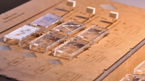
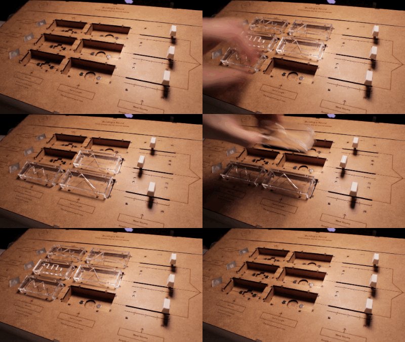
Sound Blocks is a tool to teach children and adults what sound is made of. The project was shortlisted in the Expression category of the IXDA Interaction Awards and it was developed by John Ferreira, Alejandra Molina, Andreas Refsgaard at the CIID using Arduino.

The device allows people to learn how, with a few parameters, it’s possible to create new sounds and, also, imitate real world sounds. Users can control waveform, sound decay or wave length and volume of three channels, all mixed together:

Sound blocks first and foremost was created as a tool to experiment with sound, it is playful and engaging.

Watch the video interview to discover more about the project and hear some noise:

Smart Foosball Keeps Score using Arduino Mega

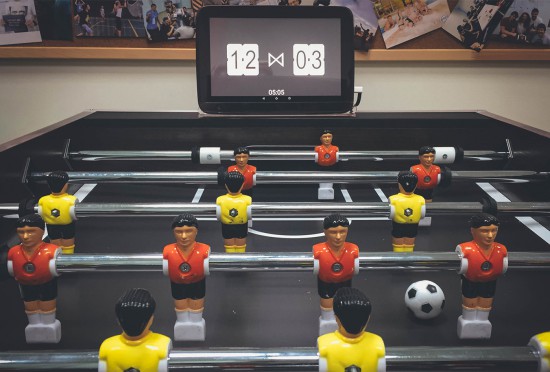
Thinkers and makers at Handsome created an automated Foosball Scoreboard using an Android tablet and Arduino Mega 2560:

the Arduino is responsible only for detecting a) a goal scored and b) the gate in which it was scored. After a goal is detected the Arduino sends this data to Android tablet.

You can explore the details of the project on this blog, the sketch on Github, and watch the video below:


An Arduino-based Cellular Automata with OLED monitor

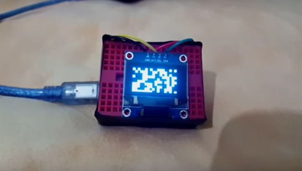
RuntimeProject made a tutorial to create a little cellular automata on a small 126×64 OLED using Arduino Nano.

He worked on one type of cellular automata, the Game of Life by John Conway, which has a grid of cells each having 2 states True or False/on or off/alive or dead. These cells are governed by 2 simple rules:

Rule 1: A cell which is dead and is surrounded by exactly 3 alive cells, will be born

Rule 2: A cell which is alive and has either 3 or 2 alive cells will remain alive, else it dies

The Arduino-based Cellular Automata works using 2 libraries the,  Adafruit GFX library  to handle all graphics and text displayed on the OLED;
Adafruit SSD1306 library which is the driver for the OLED.

You can read more info on how to make it on his blog and download the sketch on Github.

Monitoring Solitary Bees Using Open Technology

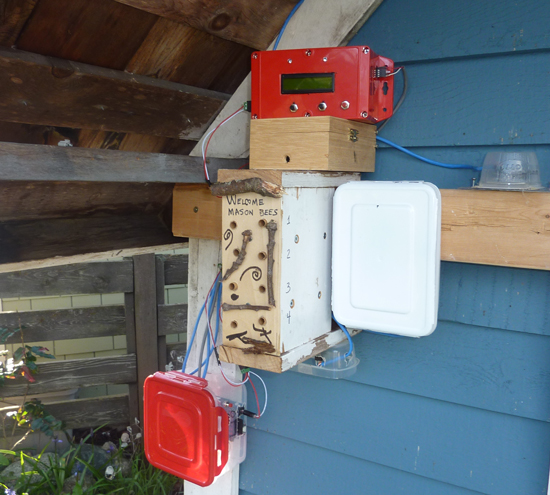
“Bees in the Backyard” is a citizen science technology project to investigate the nesting behavior of Mason bees, created by Mike Teachman, amateur bee enthusiast and Paul Perrault senior field applications engineer.

Mason bees are somewhat unique because, unlike honeybees, they are solitary, every female is fertile, there are no worker bees, they carry pollen on their bellies, they nest in holes and are vital to pollination of many fruit trees.

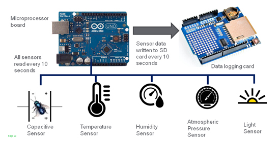
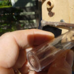
The idea behind the project was to turn each bee’s entire nest into a capacitive sensor with the use of off-the-shelf open source hardware like Arduino Uno:

Following the innovative work of the UPEI in using non-invasive capacitance sensors to detect bees entering and exiting a hive, we decided to extend this study to determine if we could measure not just a bee moving past an opening in a hive, but actually measure bee activity, along with a sense of their deliveries. This involved the invention of a new type of non-invasive sensor, along with the development of a measurement system that would be used to gather large amounts of data.


The plan for the team for 2016 is to improve the project deploying an improved monitoring system at the same site and in particular:
• Develop a new capacitance sensor tube with increased accuracy
• Improve the visual appeal of nesting block and associated electronics
• Develop algorithms to mine the measurement dataset for bee activity patterns

Watch other videos on this youtube channel and read more about the project on Spectrum IEEE.

Arduino Blog 23 Feb 16:21
arduino  bees  featured  projects  science  uno  

Trojan 77: a gamified simulation of the Trojan virus

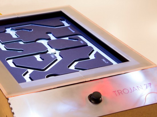
Trojan 77 is a gamified simulation of the Trojan virus running on Arduino Uno. The Trojan is a malware designed to provide unauthorised remote access to a user’s computer amongst other harmful possibilities and this prototype was designed to be exhibited at a technology museum to show the most important effects the virus. Inspired by the tilting labyrinth game, the prototype simulates a few key effects of the Trojan virus like passwords leaking out, files being deleted and culminating in a system crash.

Trojan 77  was created by a team of Physical Computing students (Dhrux Saxena, Gunes Kantaroglu, Liliana Lambriev, Karan Chaitanya Mudgal) at CIID:

The idea of designing something analog to explain a digital construct was an exciting challenge to undertake. The way that computer viruses operate can be very complicated and hard to explain without overloading people with detailed information. Making this information visual via animated projections helped to communicate the effects in a fun and memorable way.

The Trojan moved through several prototyping stages. Initially, the wooden structure was built, followed by the maze. The structure as a whole became functional with the addition of Arduino and Processing. Two servo motors controlled by a joystick enabled the tilt while the movement of the ball triggered distinct light sensors which in turn triggered events in a Processing sketch mapped onto the maze.

The students created also a great video documentary  to explain the project with a style inspired by the work  of Charles and Ray Eames:

Macchina poetica converts sounds into onomatopoeic words


Macchina Poetica is a digital prototype converting sounds into onomatopoeic words and images and it’s inspired by the art of the Futurism movement.

Futurism is a modernist, avant-garde artistic movement originated in Italy in the early 20th century. Thanks to sound representation, Futurism artists aimed to emphasize speed, technology, youth and violence, all concepts arising from industrial innovations and war.

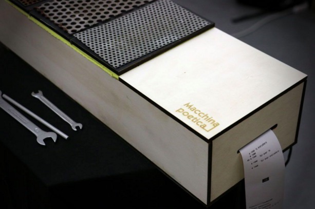
In order to keep continuity with this particular artistic movement, the authors, Alessandra Angelucci, Aris Dotti, Rebecca Guzzo, students at Master of Advanced Studies in Interaction Design SUPSI, decided to design an object that looks like the musical instrument of Futurism movement (precisely a Celesta). The object plays a metallic sounds and the user is facilitated in understanding how to use the object due to a instrument-like interface.

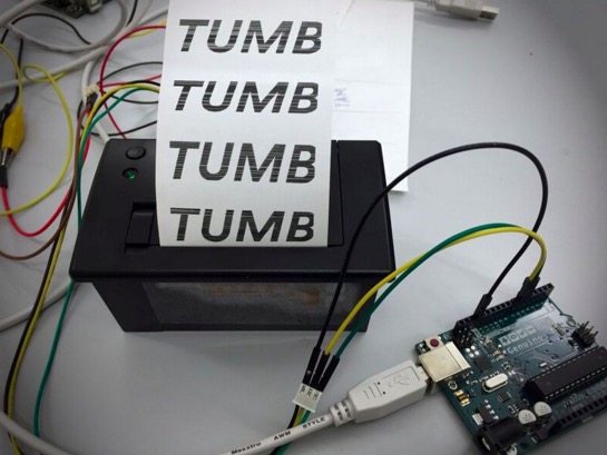
The machine is built using 4 piezo sensors, a thermal printer, a board, electrical cables, 4 resistors (1K), a 6 volt power supply and a Genuino Uno board.

The instrument’s interface is designed with plywood, metal plates and sponge that serves as a shock absorber. Between the metal plates and the sponge there are the piezo sensors along with resistors communicating with the Genuino Uno board every time the user interacts with the metallic plates. Once the Genuino receives the signal, it sends a command to the thermal printer that will print a word or a Futurism poem.

The interaction takes place when the user with the help of a metal tool (for example a screwdriver or a wrench) strikes the metal plates with different pressures. At the end of the performance the user and the viewers can have a clear overview of the produced sounds reviewing the printed paper outputs.

The prototype is the result of two weeks physical computing class Creating Tangible Interfaces held by Ubi De Feo at Maind program SUPSI  in Lugano, the goal of the course is how to make tangible interfaces via learning fundamentals of electronics prototyping and interaction design.  (Applications are open for the next edition 2016/2017 starting in September 2016)