Posts with «hdsp» label

Enclosure ideas for WiFiChron and other clocks

It turns out that most electronics, even prototypes, can be easily enclosed with Lego. And that means no screws, no glue, no fasteners, zero tools, just the bricks and some imagination.

This is the HDSP clock variant with 1" displays driven by HT16K33 (introduced here). The board was cut and filed (0.5mm on each side) to fit snug between the walls (see this).


Next is a HDSP clock variant with two Adafruit Quad Alphanumeric displays.


Similarly, the PCB was cut and filed a bit. The assembly fits solidly between the bricks (no movement when shaken). As in the previous build, the exposed PCB is kind-of-required to allow access to the two buttons (set hours, set minutes).

Both of the above can be mounted on a Lego wall (as found in schools) or they can desk-stand on their own.

Here is an example of a Lego-encapsulated WifiChron.


The PCB was also filed about 0.5mm on each side to fit between the lateral brick walls. It did not have to be fastened in any other way. The ESP8266 module fits inside nicely. The 3 buttons and the USB mini B connector are all easily accessible from the back.

Below is the Lego version of the Axiris clock.


Since it does not have any buttons, the time is set through Bluetooth (command "SET TIME=hh:mm", sent from Terminal app while BT paired).

And finally, a couple of OLED clocks, both running the same software on similar hardware: pro-mini + OLED shield and wsduino + 2.42" OLED shield, respectively.


Note that this is the prototype version, using a LiPo battery with charger (similar to the one shown here).


Again, all the above enclosures feel solid: nothing moves or rattles when upside down or even shaken. I did not try dropping them though :)

And lastly, the WiFiChron with Adafruit quad 0.56" displays from the previous post, sandwiched between scrap plexiglass plates:


More WiFiChron variants

This post shows two WiFiChron mods, that look more like finished projects rather than just experiments.

First one uses the WiFiChron board connected on I2C to two Adafruit Quad Alphanumeric Displays (I2C addresses 0x70 and 0x71). The WiFiChron software has similar adaptation as the one for HDSP clock (see this post for details).


Did I mention that two plexiglass plates are still waiting to be cut and screwed in the standoffs?

This (poor) video shows it in action.

The interesting thing about the Chinese clones (of the Adafruit displays) I had in hand is that each module has one (2 digit) display red and the other orange. Initially I thought it's a manufacturing error, but after checking, it seems that this is intended (for reasons I do not understand).

The second one is an "HDSP clock" with a 8-character display with 16-segment LED modules, introduced here, cased in a LEGO enclosure.

After cutting the top of board off (since there is no HDSP-2534) and a little filing of all sides, the PCB fit perfectly between the LEGO bricks.


For this display, the line that has to be enabled (un-commented) in DAL.h is:

#define DISPLAY_HT16K33


Alternative displays for HDSP or WiFiChron clocks

So you would like to build your own HDSP clock or WiFiChron clock but you find the HDSP-2534 display too small or too expensive. Why not just replace it with a bigger 8-character display, like the 1-inch 8 x 16-segment or two cascaded Adafruit 0.54" 4 x 14-segment backpacks? We have you covered, in software. Both these displays are now supported, as extension classes of the DAL (Display Abstraction Layer), together with the 128x64 I2C OLED and the HT1632-based 32x8 LED matrix display (used to be from Sure  Electronics). Support could be further extended to LCD displays (think big font on 40x4), MAX6955 with 8 x 16 segment etc., basically anything that can show 8 alphanumeric characters (numbers only, like regular Nixie tubes, would not suffice).

Below are some examples.

Two Adafruit 4-character backpacks are connected on I2C, addresses 0x70 (default) and 0x71, handled by class DisplayAda14seg, which in turn uses the Adafruit_LEDBackpack library.


To enable this display, uncomment the line (in DAL.h, comment out the rest):
#define DISPLAY_ADA_14SEG  // 2 x Adafruit 4x14seg displays;

Functionality for the 8x32 (or 16x32) LED matrix display is implemented in class DisplayHT1632, which is based on code recycled from Wise Clock 4. To enable this display, simply uncomment the line (in DAL.h, comment out the others):
#define DISPLAY_HT1632	 // Sure 8x32 LED matrix controlled by HT1632;


To accommodate the 8 characters on a 32-pixel line, fontTiny had to be used (each character is 4 pixels wide).

Note the connections for the HT1632 display (in DisplayHT1632.cpp):
#define HT1632_DATA 4 // Data pin (pin 7 of display connector)
#define HT1632_CS         3      // Chip Select (pin 1 of display connnector)
#define HT1632_WRCLK 2 // Write clock pin (pin 5 of display connector)
#define HT1632_CLK 5 // clock pin (pin 2 of display connector)

Other possible definitions in DAL.h are:
//****************************************************************************************
// Define the display you wish to use here.
// Comment out the ones not used.

//#define DISPLAY_HDSP2534 // original HDSP-2534 display in HDSP clock;
//#define DISPLAY_HUB08 // TODO: 8x32 LED matrix display with cascading shift registers (?)
//#define DISPLAY_DL1414 // 2 x DL1414; tested June 23, 2018 (http://timewitharduino.blogspot.com/2018/06/wifichron-adapter-for-dl-1414-displays.html)
//#define DISPLAY_HT16K33 // my 8x16-segment driven by HK16K33, tested Jul 26, 2020;
//#define DISPLAY_OLED // I2C OLED; tested
#define DISPLAY_HT1632 // Sure 8x32 LED matrix controlled by HT1632; tested Aug 14, 2020;
//#define DISPLAY_MAX6955 // TODO: 8x16 segment driven by MAX6955
//#define DISPLAY_LCD1602 // TODO: classic LCD 16x2 (or better 40x4, with big font);
//#define DISPLAY_ADA_14SEG // 2 x Adafruit 4x14seg displays, wired on 0x70 and 0x71 I2C addresses; tested Jul 26, 2020;

// show time on the 60-pixel Adafruit Neopixel ring;
//#define _ADD_NEOPIXEL_
//****************************************************************************************


And so on.


Alternative displays for HDSP or WiFiChron clocks

So you would like to build your own HDSP clock or WiFiChron clock but you find the HDSP-2534 display too small or too expensive. Why not just replace it with a bigger 8-character display, like the 1-inch 8 x 16-segment or two cascaded Adafruit 0.54" 4 x 14-segment backpacks? We have you covered, in software. Both these displays are now supported, as extension classes of the DAL (Display Abstraction Layer), together with the 128x64 I2C OLED and the HT1632-based 32x8 LED matrix display (used to be from Sure  Electronics). Support could be further extended to LCD displays (think big font on 40x4), MAX6955 with 6x16 segment etc., basically anything that can show 8 alphanumeric characters (numbers only, like regular Nixie tubes, would not suffice).

Below are some examples.

Two Adafruit 4-character backpacks are connected on I2C, addresses 0x70 (default) and 0x71, handled by class DisplayAda14seg, which in turn uses the Adafruit_LEDBackpack library.


To enable this display, uncomment the line (in DAL.h, comment out the rest):
#define DISPLAY_ADA_14SEG  // 2 x Adafruit 4x14seg displays;

Functionality for the 8x32 (or 16x32) LED matrix display is implemented in class DisplayHT1632, which is based on code recycled from Wise Clock 4. To enable this display, simply uncomment the line (in DAL.h, comment out the others):
#define DISPLAY_HT1632	 // Sure 8x32 LED matrix controlled by HT1632;


To accommodate the 8 characters on a 32-pixel line, fontTiny had to be used (each character is 4 pixels wide).

Other possible definitions in DAL.h are:
//****************************************************************************************
// Define the display you wish to use here.
// Comment out the ones not used.

//#define DISPLAY_HDSP2534 // original HDSP-2534 display in HDSP clock;
//#define DISPLAY_HUB08 // TODO: 8x32 LED matrix display with cascading shift registers (?)
//#define DISPLAY_DL1414 // 2 x DL1414; tested June 23, 2018 (http://timewitharduino.blogspot.com/2018/06/wifichron-adapter-for-dl-1414-displays.html)
//#define DISPLAY_HT16K33 // my 8x16-segment driven by HK16K33, tested Jul 26, 2020;
//#define DISPLAY_OLED // I2C OLED; tested
#define DISPLAY_HT1632 // Sure 8x32 LED matrix controlled by HT1632; tested Aug 14, 2020;
//#define DISPLAY_MAX6955 // TODO: 8x16 segment driven by MAX6955
//#define DISPLAY_LCD1602 // TODO: classic LCD 16x2 (or better 40x4, with big font);
//#define DISPLAY_ADA_14SEG // 2 x Adafruit 4x14seg displays, wired on 0x70 and 0x71 I2C addresses; tested Jul 26, 2020;

// show time on the 60-pixel Adafruit Neopixel ring;
//#define _ADD_NEOPIXEL_
//****************************************************************************************


And so on.


HDSP clock fully through-hole revision 3

The only SMD component in the HDSP clock was the USB miniB connector. To make the kit completely beginner-friendly, this connector was replaced by either of its two (right angle or straight) through hole equivalents. Other changes (from revision 2) are:
  • fixed the two smaller pads for DS1307
  • some re-routing (which reduced the number of vias to 5)

The TH right angle USB connector is to be mounted on the top, as shown below.


The straight USB connector can only be mounted on the bottom side of the PCB, as shown below.


This latter configuration allows the clock to be used without any additional enclosure, with just two standoffs holding it in a vertical position, like this:


Assembly instructions for the HDSP clock kit can be found here, with the only difference being the last step, where the miniB USB connector is soldered.


Wise time with Arduino 01 Aug 02:11
hdsp  

HDSP clock with SCD5583 display

Here is another interesting "intelligent" LED matrix display, whose name actually makes some sense (unlike HDSP-2354, among many others): SCD5583A. I reckon it means: "Serial Character Display with 5x5x8 dot matrix". 3 is the code for green (0 for red, 1 for yellow).
This display is now obsolete (replaced by touch screens in avionics, the industry for which it was designed), but it is still available on ebay for a reasonable price (except for incredibly high shipping cost).

Compared to other intelligent displays like the above-mentioned HDSP-2534 employed by the HDSP clock (hence the bland unimaginative name), SCD558X does not have an internally-defined font and requires the user to provide one. This makes it a little more complicated to use, but also allows for more flexibility, making it truly international (non-English character set). Even more, each pixel can be addressed individually, like a graphical 5x40 LED matrix.
The fact that is serial means fewer pins are required for interfacing (3 control pins in this case) and less driving circuitry (no need for the external shift register).

The photo below shows the display connected to an Arduino and running the HDSP sketch adapted for SCD5833.


Practically, the HDSP sketch uses only one function to write to display, aptly called "writeDisplay()", that needs to be re-written. The support for SCD5583 is provided by the class SCD5583, shown below (header + cpp files, compiled with Arduino IDE 1.8.13).

#ifndef _SCD5583_H_
#define _SCD5583_H_

#include  "Arduino.h"

class SCD5583
{
  public:
    SCD5583(byte loadPin, byte dataPin, byte clkPin);
    void clearMatrix();
    void setBrightness(byte b);
    void writeLine(char text[9]);

  private:
    void _sendData(byte data);
    void _getCharDefinition(byte* rows, char c);
    void _selectIndex(byte position);

    byte _loadPin;
    byte _dataPin;
    byte _clkPin;
};

#endif // _SCD5583_H_
-----------------------------------------------
#include "SCD5583.h"
#include "font5x5.h"

#define MAX_CHARS 8   // set to 10 for SCD5510X (10 digits) or to 4 for SCD554X (4 digits);
#define NUM_ROWS  5

SCD5583::SCD5583(byte loadPin, byte dataPin, byte clkPin)
{
  pinMode(loadPin, OUTPUT);
  pinMode(dataPin, OUTPUT);
  pinMode(clkPin, OUTPUT);
  _loadPin = loadPin;
  _dataPin = dataPin;
  _clkPin  = clkPin;
  clearMatrix();
//  setBrightness(0);
}

void SCD5583::clearMatrix()
{
  _sendData(B11000000);
}

void SCD5583::setBrightness(byte b)
{
  if (b > 0 && b < 7)
  {
     _sendData(B11110000 + b);
  }
}

void SCD5583::_selectIndex(byte position)
{
   _sendData(B10100000 + position);
}

void SCD5583::_sendData(byte data)
{
  byte mask = 1;
  digitalWrite(_loadPin, LOW);
  digitalWrite(_clkPin,  LOW);
  for (byte i = 0; i < 8; i++)
  {
    digitalWrite(_dataPin, mask & data? HIGH : LOW);
    digitalWrite(_clkPin, HIGH);
//  delay(10);
    digitalWrite(_clkPin, LOW);
    mask = mask*2;
  }
  digitalWrite(_loadPin, HIGH);
}

void SCD5583::_getCharDefinition(byte* rows, char c)
{
  for (byte i = 0; i < NUM_ROWS; i++)
  {
    rows[i] = font5x5[((c- 0x20) * NUM_ROWS) + i];
  }
}

void SCD5583::writeLine(char* text)
{
  byte rows[NUM_ROWS];
  for (int i = 0; i < MAX_CHARS; i++)
  {
    _selectIndex(i);
    _getCharDefinition(rows, text[i]);
    for (int r = 0; r < NUM_ROWS; r++)
    {
      _sendData(rows[r]);
    }
  }
}

As mentioned previously, the font must be provided too (content of file "font5x5.h" shown below):

#ifndef _FONT5X5_H_
#define _FONT5X5_H_

// ascii characters 0x41-0x7a (32-127);
static unsigned char font5x5[] =
{
  0x00, 0x20, 0x40, 0x60, 0x80, // space
  0x04, 0x24, 0x44, 0x60, 0x84, // !
  0x0A, 0x2A, 0x40, 0x60, 0x80, // "
  0x0A, 0x3F, 0x4A, 0x7F, 0x8A, // #
  0x0F, 0x34, 0x4E, 0x65, 0x9E, // $
  0x19, 0x3A, 0x44, 0x6B, 0x93, // %
  0x08, 0x34, 0x4D, 0x72, 0x8D, // &
  0x04, 0x24, 0x40, 0x60, 0x80, // '
  0x02, 0x24, 0x44, 0x64, 0x82, // (
  0x08, 0x24, 0x44, 0x64, 0x88, // )
  0x15, 0x2E, 0x5F, 0x6E, 0x95, // *
  0x04, 0x24, 0x5F, 0x64, 0x84, // +
  0x00, 0x20, 0x40, 0x64, 0x84, // ,
  0x00, 0x20, 0x4E, 0x60, 0x80, // -
  0x00, 0x20, 0x40, 0x60, 0x84, // .
  0x01, 0x22, 0x44, 0x68, 0x90, // /
  0x0E, 0x33, 0x55, 0x79, 0x8E, // 0
  0x04, 0x2C, 0x44, 0x64, 0x8E, // 1
  0x1E, 0x21, 0x46, 0x68, 0x9F, // 2
  0x1E, 0x21, 0x4E, 0x61, 0x9E, // 3
  0x06, 0x2A, 0x5F, 0x62, 0x82, // 4
  0x1F, 0x30, 0x5E, 0x61, 0x9E, // 5
  0x06, 0x28, 0x5E, 0x71, 0x8E, // 6
  0x1F, 0x22, 0x44, 0x68, 0x88, // 7
  0x0E, 0x31, 0x4E, 0x71, 0x8E, // 8
  0x0E, 0x31, 0x4F, 0x62, 0x8C, // 9
  0x00, 0x24, 0x40, 0x64, 0x80, // :
  0x00, 0x24, 0x40, 0x6C, 0x80, // ;
  0x02, 0x24, 0x48, 0x64, 0x82, // <
  0x00, 0x3F, 0x40, 0x7F, 0x80, // =
  0x08, 0x24, 0x42, 0x64, 0x88, // >
  0x0E, 0x31, 0x42, 0x64, 0x84, // ?
  0x0E, 0x35, 0x57, 0x70, 0x8E, // @
  0x04, 0x2A, 0x5F, 0x71, 0x91, // A
  0x1E, 0x29, 0x4E, 0x69, 0x9E, // B
  0x0F, 0x30, 0x50, 0x70, 0x8F, // C
  0x1E, 0x29, 0x49, 0x69, 0x9E, // D
  0x1F, 0x30, 0x5E, 0x70, 0x9F, // E
  0x1F, 0x30, 0x5E, 0x70, 0x90, // F
  0x0F, 0x30, 0x53, 0x71, 0x8F, // G
  0x11, 0x31, 0x5F, 0x71, 0x91, // H
  0x0E, 0x24, 0x44, 0x64, 0x8E, // I
  0x01, 0x21, 0x41, 0x71, 0x8E, // J
  0x13, 0x34, 0x58, 0x74, 0x93, // K
  0x10, 0x30, 0x50, 0x70, 0x9F, // L
  0x11, 0x3B, 0x55, 0x71, 0x91, // M
  0x11, 0x39, 0x55, 0x73, 0x91, // N
  0x0E, 0x31, 0x51, 0x71, 0x8E, // O
  0x1E, 0x31, 0x5E, 0x70, 0x90, // P
  0x0C, 0x32, 0x56, 0x72, 0x8D, // Q
  0x1E, 0x31, 0x5E, 0x74, 0x92, // R
  0x0F, 0x30, 0x4E, 0x61, 0x9E, // S
  0x1F, 0x24, 0x44, 0x64, 0x84, // T
  0x11, 0x31, 0x51, 0x71, 0x8E, // U
  0x11, 0x31, 0x51, 0x6A, 0x84, // V
  0x11, 0x31, 0x55, 0x7B, 0x91, // W
  0x11, 0x2A, 0x44, 0x6A, 0x91, // X
  0x11, 0x2A, 0x44, 0x64, 0x84, // Y
  0x1F, 0x22, 0x44, 0x68, 0x9F, // Z
  0x07, 0x24, 0x44, 0x64, 0x87, // [
  0x10, 0x28, 0x44, 0x62, 0x81, // \
  0x1C, 0x24, 0x44, 0x64, 0x9C, // ]
  0x04, 0x2A, 0x51, 0x60, 0x80, // ^
  0x00, 0x20, 0x40, 0x60, 0x9F, // _
  0x0A, 0x2A, 0x40, 0x60, 0x80, // '
  0x00, 0x2E, 0x52, 0x72, 0x8D, // a
  0x10, 0x30, 0x5E, 0x71, 0x9E, // b
  0x00, 0x2F, 0x50, 0x70, 0x8F, // c
  0x01, 0x21, 0x4F, 0x71, 0x8F, // d
  0x00, 0x2E, 0x5F, 0x70, 0x8E, // e
  0x04, 0x2A, 0x48, 0x7C, 0x88, // f
  0x00, 0x2F, 0x50, 0x73, 0x8F, // g
  0x10, 0x30, 0x56, 0x79, 0x91, // h
  0x04, 0x20, 0x4C, 0x64, 0x8E, // i
  0x00, 0x26, 0x42, 0x72, 0x8C, // j
  0x10, 0x30, 0x56, 0x78, 0x96, // k
  0x0C, 0x24, 0x44, 0x64, 0x8E, // l
  0x00, 0x2A, 0x55, 0x71, 0x91, // m
  0x00, 0x36, 0x59, 0x71, 0x91, // n
  0x00, 0x2E, 0x51, 0x71, 0x8E, // o
  0x00, 0x3E, 0x51, 0x7E, 0x90, // p
  0x00, 0x2F, 0x51, 0x6F, 0x81, // q
  0x00, 0x33, 0x54, 0x78, 0x90, // r
  0x00, 0x23, 0x44, 0x62, 0x8C, // s
  0x08, 0x3C, 0x48, 0x6A, 0x84, // t
  0x00, 0x32, 0x52, 0x72, 0x8D, // u
  0x00, 0x31, 0x51, 0x6A, 0x84, // v
  0x00, 0x31, 0x55, 0x7B, 0x91, // w
  0x00, 0x32, 0x4C, 0x6C, 0x92, // x
  0x00, 0x31, 0x4A, 0x64, 0x98, // y
  0x00, 0x3E, 0x44, 0x68, 0x9E, // z
  0x06, 0x24, 0x48, 0x64, 0x86, // {
  0x04, 0x24, 0x44, 0x64, 0x84, // |
  0x0C, 0x24, 0x42, 0x64, 0x8C, // }
  0x00, 0x27, 0x5C, 0x60, 0x80, // ~
};

#endif  // _FONT5X5_H_

And finally, the changes in HDSP.ino are:

1. add the following line at the top:
#include "SCD5583.h"

// SCD5583 pins: LOAD to D4, DATA to D5, SDCLK to D3;
SCD5583 scd(4,5,3);
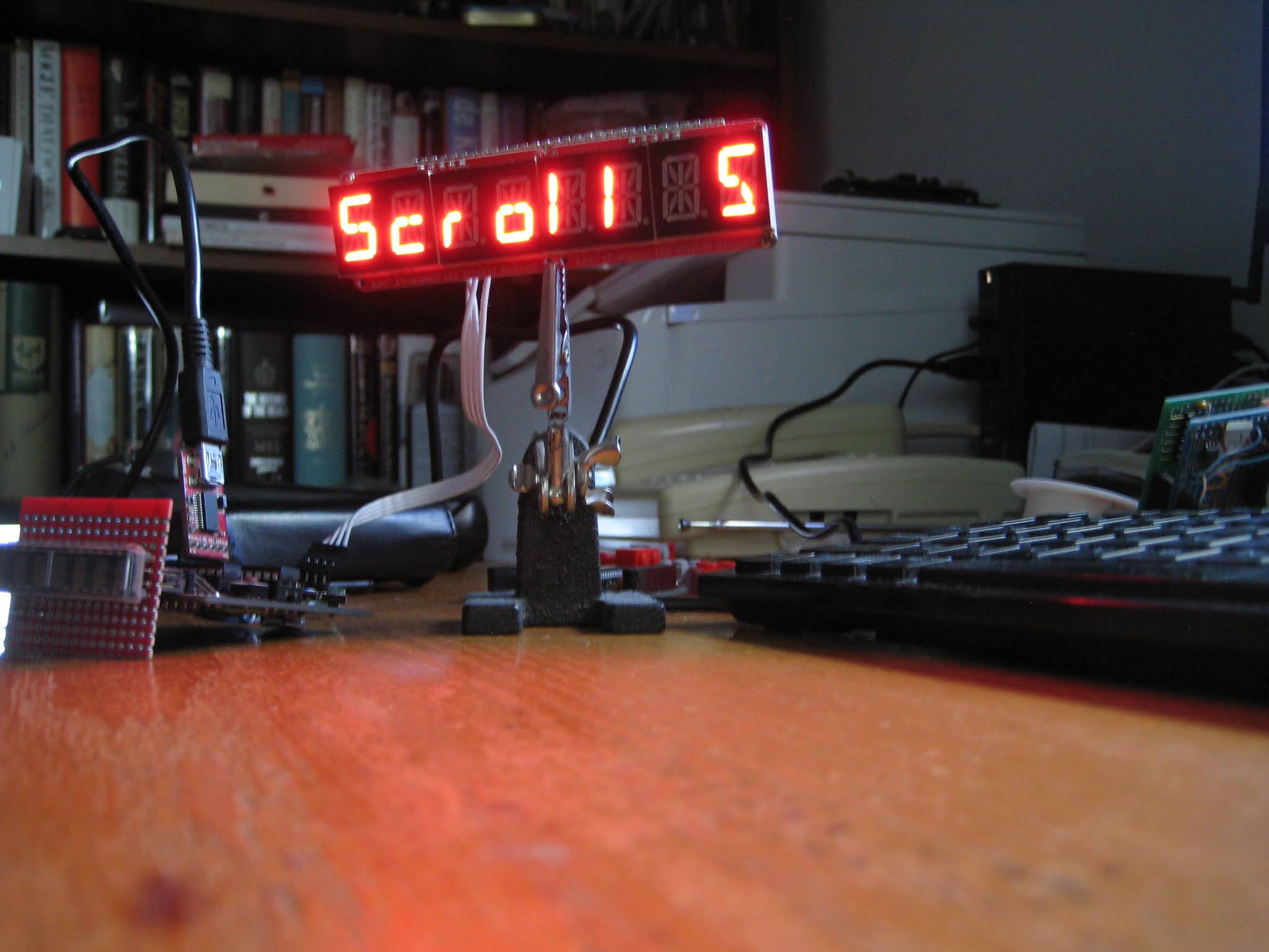
2. replace the function writeDisplay() written for HDSP-2534, with the following:
void writeDisplay()
{
  scd.writeLine(displayBuffer);
}

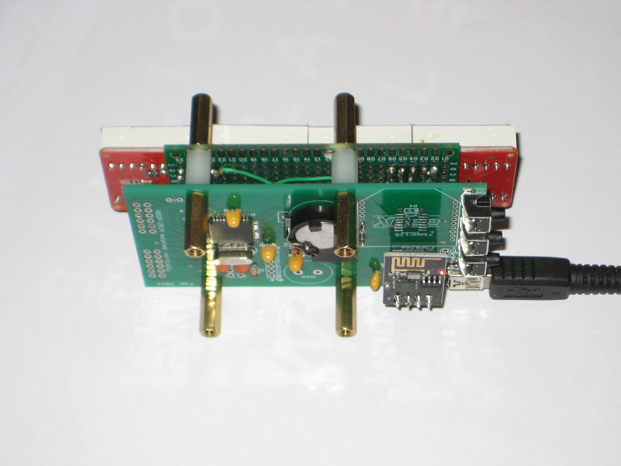
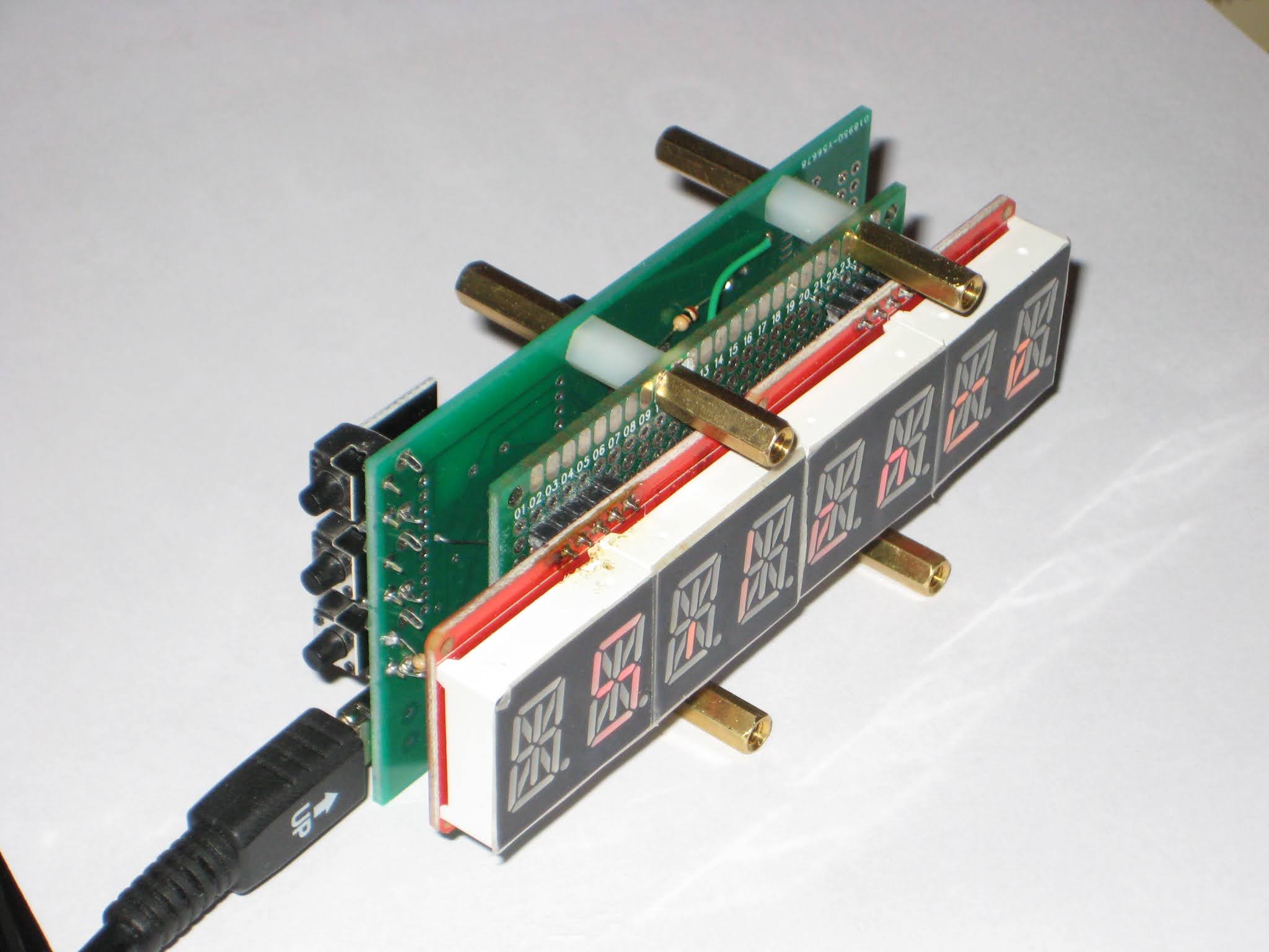
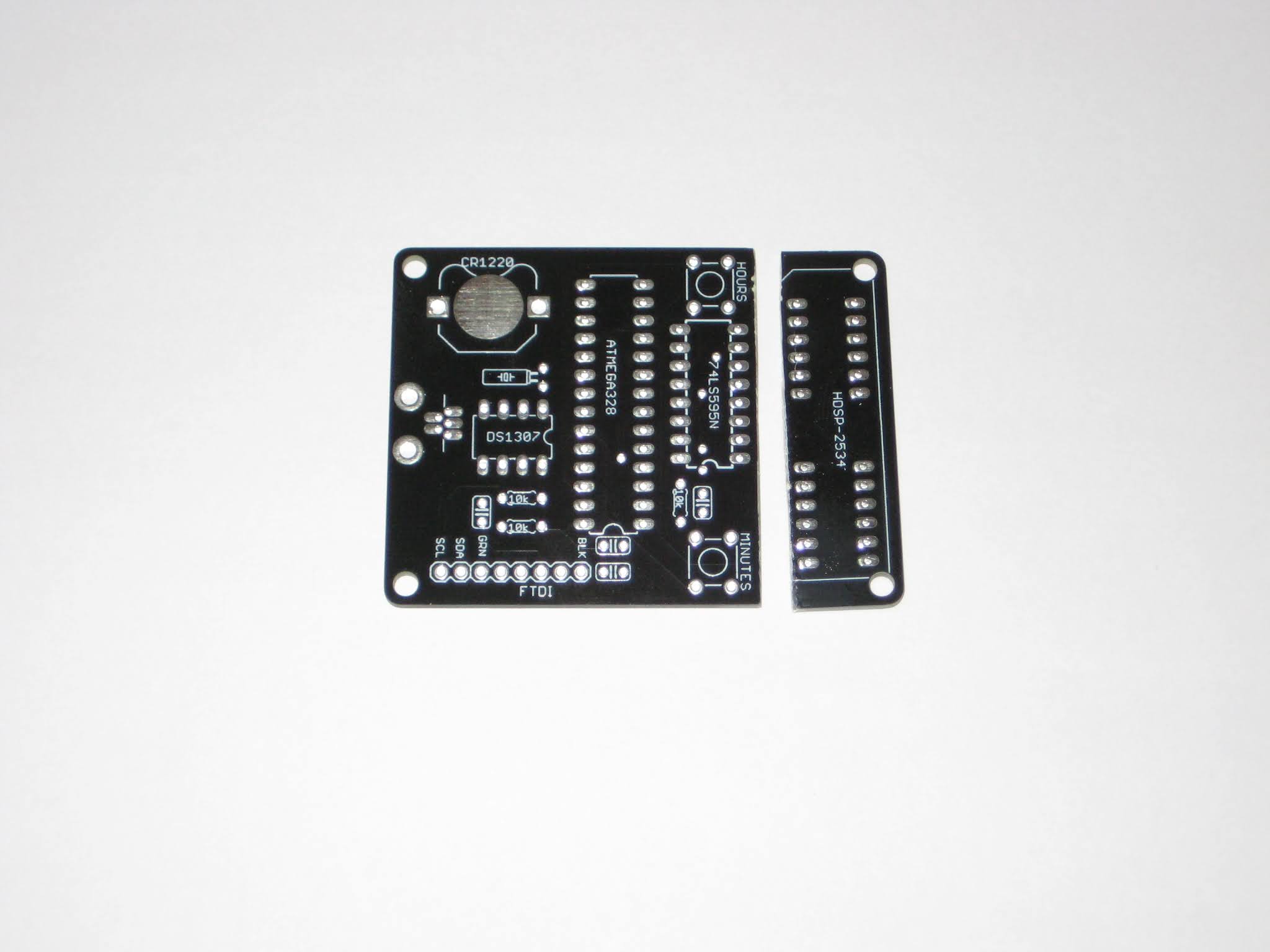
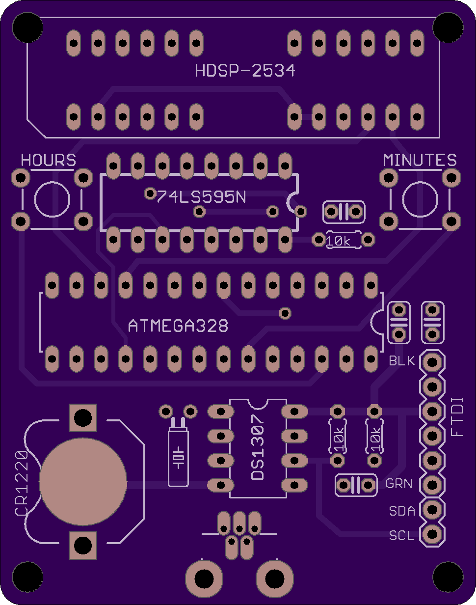
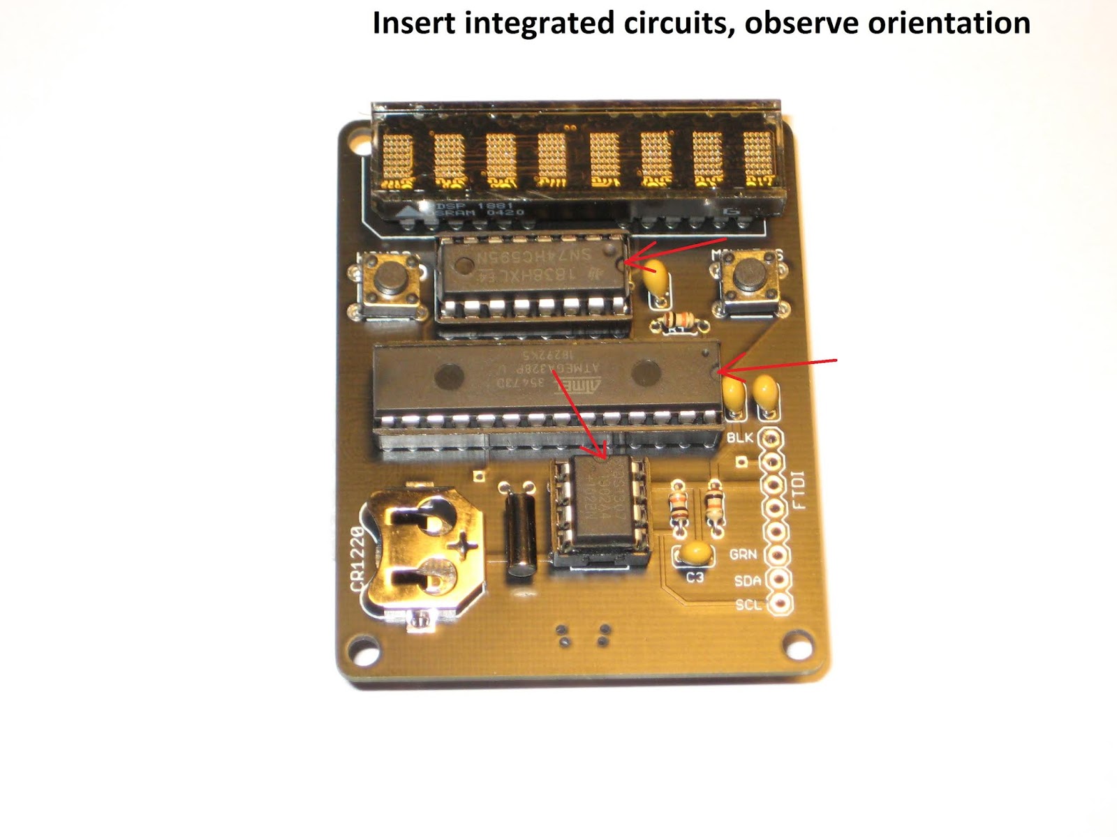
Hardware-wise, some re-wiring is required on the HDSP board, starting with the removal of the 595 shift register. Then, D3, D4 and D5 (ATmega328 pins 5, 6, 11) must be connected respectively to SDCLK, LOAD and DATA pins (1, 2, 27) of the SCD5583 display.

And there you have it, a working HDSP clock with SCD5583 display.

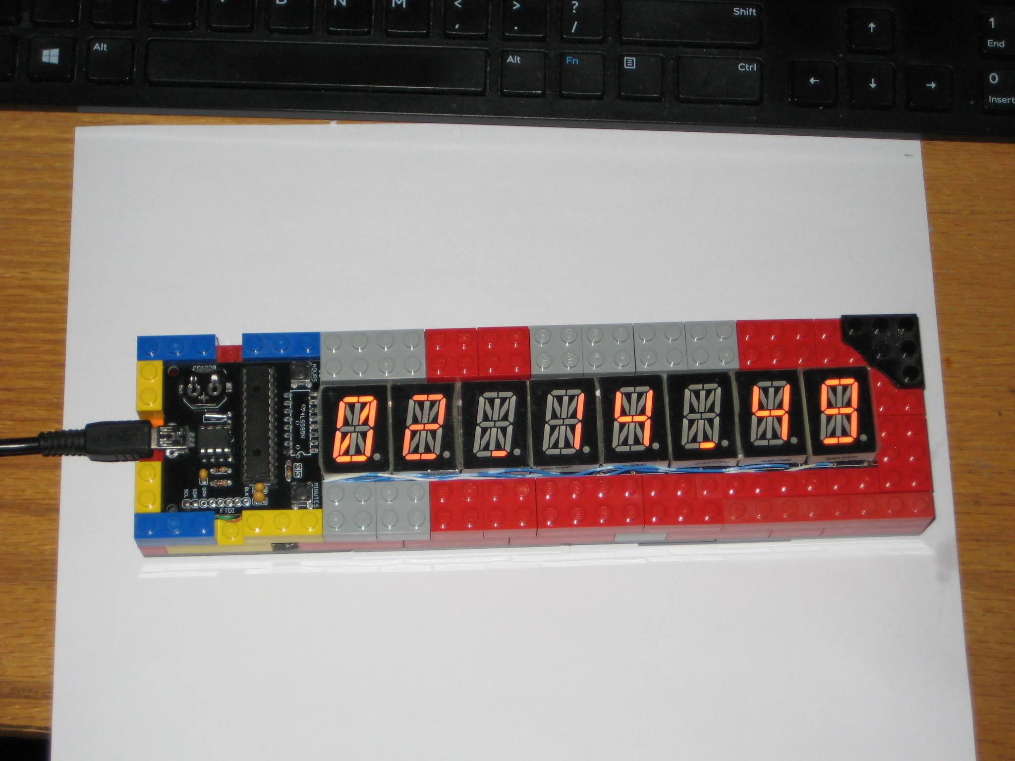
It is worth mentioning that the measured current drawn was between 10mA (lowest brightness) and 20mA (highest), and that it works similarly well when powered by 3V3.


HDSP clock revision 2

The latest revision of the HDSP clock uses the same schematic, but offers an improved PCB layout, with:
  • 4 holes in the corners, for encasing;
  • addition of I2C signals to the FTDI connector, for expansion;
  • the regular push buttons can be replaced with 2-pin right angle buttons;

This revision was successfully used as the assembly kit in the "Introduction to Practical Electronics" course for Grade 6 students.

This would also be a good place for step-by-step assembly instructions, for those who require directions.


melt a bit of solder on the battery pad, to raise it (not pictured)


slide in the CR1220 battery, flat side (+ pole) up (not pictured)


Use a mini B USB cable to power the clock. It should work right away, since the processor is already programmed with the clock software. Use the "Hours" (left) and "Minutes" (right) buttons to set up the time.
Also, insert the CR1220 battery into the holder. It powers the DS1307 RTC (real time clock) when the clock board is disconnected from USB. Note that the small coin battery ONLY powers the RTC integrated circuit, and not the whole clock. The display is lit only when connected to the USB power.

Troubleshooting
  • check for missing soldering joints; you may have forgotten to solder some terminals;
  • check for solder bridges; solder blobs may accidentally connect adjacent holes/terminals that should not be connected;
  • make sure the orientation of the integrated circuits and the display matches the silkscreen, by checking the notches/indentations;
  • ensure that the ICs are fully and completely pushed in the socket, until their bottoms touch the socket's plastic;

What's next

1. Catch up on the theory:
  • recognize components symbols in schematics;
  • recap units of measure for some of the components (ohms for resistors, farads for capacitors); read their intended values (3 digits, color code), measure their real values using a multimeter;
  • understand electrical concepts: voltage, current, resistance (and their dependency), frequency; recap their units of measure;
2. Design and make an enclosure (hint: the easiest is to sandwich the board between plates of transparent acrylic, with standoffs in the 4 corners).

3. Look for a new kit to assemble.

Clock super-display

Today was a good day. In typical fashion, I started a few new "projects" almost in the same time. First one, it's assembling of a new kind of clock, from a kit sent by Nick S. I got stuck pretty early though, so I "parked" it for now. Details to come soon, in a special post.

Second one, an "Adler 121PD" vintage calculator with a VFD display, that I found "in the dumpster" (well, not really, but the idea is the same, I got it for free). I was going to break it apart, for the display and the circuitry, but I gave up when I powered it up (with an improvised cable; the original, proprietary one, was missing) and it actually worked! I may still go ahead with dis-assembling it, since it is not a great value anyway; I checked prices on ebay, and they go for around $20.

Lastly, the project that gave the name of this post: a clock LED super-display, consisting of 3 individual and independent indicators, inspired by the Leitch studio clock, brought to my attention by Nick (VE2HOT). The goal for the clock super-display is to eventually be able to emulate the Leitch clock. Here it is, in its incipient glory (only the back panel; the black wooden frame not pictured):


Since I am not the crafty kind-of-guy (also not keen on spending for form more than for content), I am always looking for cheap, easy and quick solutions for encasing electronics. In this case, Ikea's Ribba 9"x9" frame ($10) seems to be a good fit for the job, and hopefully will help the future clock look "Leitchy" or even better (Nick's photo below):


The 2 alphanumeric displays (4 and 8 chars) of the clock super-display are I2C-driven. The 60 LED ring is adafruit neopixel, controlled by a single pin. With this setup, even an ESP8266 module could be used as the brains of the clock.

The ring is fixed to the cardboard back/panel of the deep Ikea frame with four M3 plastic standoffs glued to the PCB.
The 4-character alphanumeric 16-segment is my creation, introduced earlier. It is driven by the HT16K33 backpack, also from adafruit (not in the picture). The PCB has M3 holes for screws.
The 8-character alphanumeric is made of two side-by-side quad 14-segment LED displays, also from adafruit. The 2 modules already have the HT16K33 drivers installed (soldered on the back). Attaching these quad displays to the panel is not easy, since the holes are probably M1.4. Even these thin M1.4 screws need to be forced, because the screw head presses against display's plastic enclosure. Eventually, the M1.4 screws will be glued to the M3 plastic standoffs, that's the best I could come up with. It is weird that, for such a popular and successful product, one cannot find photos (or instructions) on mounting these modules using screws.

Next step is the software support in the WiFiChron software. Also need to find a way to access the 3 buttons: having them in the back is not a good idea, having them in the front is impossible, unless the glass is replaced with transparent/smoky/grey acrylic, which can be drilled.

Wise time with Arduino 11 May 02:13
esp8266  hdsp  i2c  wifichron