

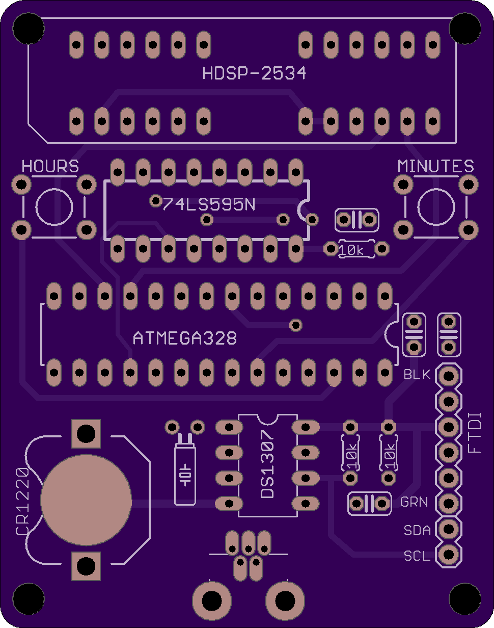
HDSP clock fully through-hole revision 3
The only SMD component in the HDSP clock was the USB miniB connector. To make the kit completely beginner-friendly, this connector was replaced by either of its two (right angle or straight) through hole equivalents. Other changes (from revision 2) are:
- fixed the two smaller pads for DS1307
- some re-routing (which reduced the number of vias to 5)
The TH right angle USB connector is to be mounted on the top, as shown below.
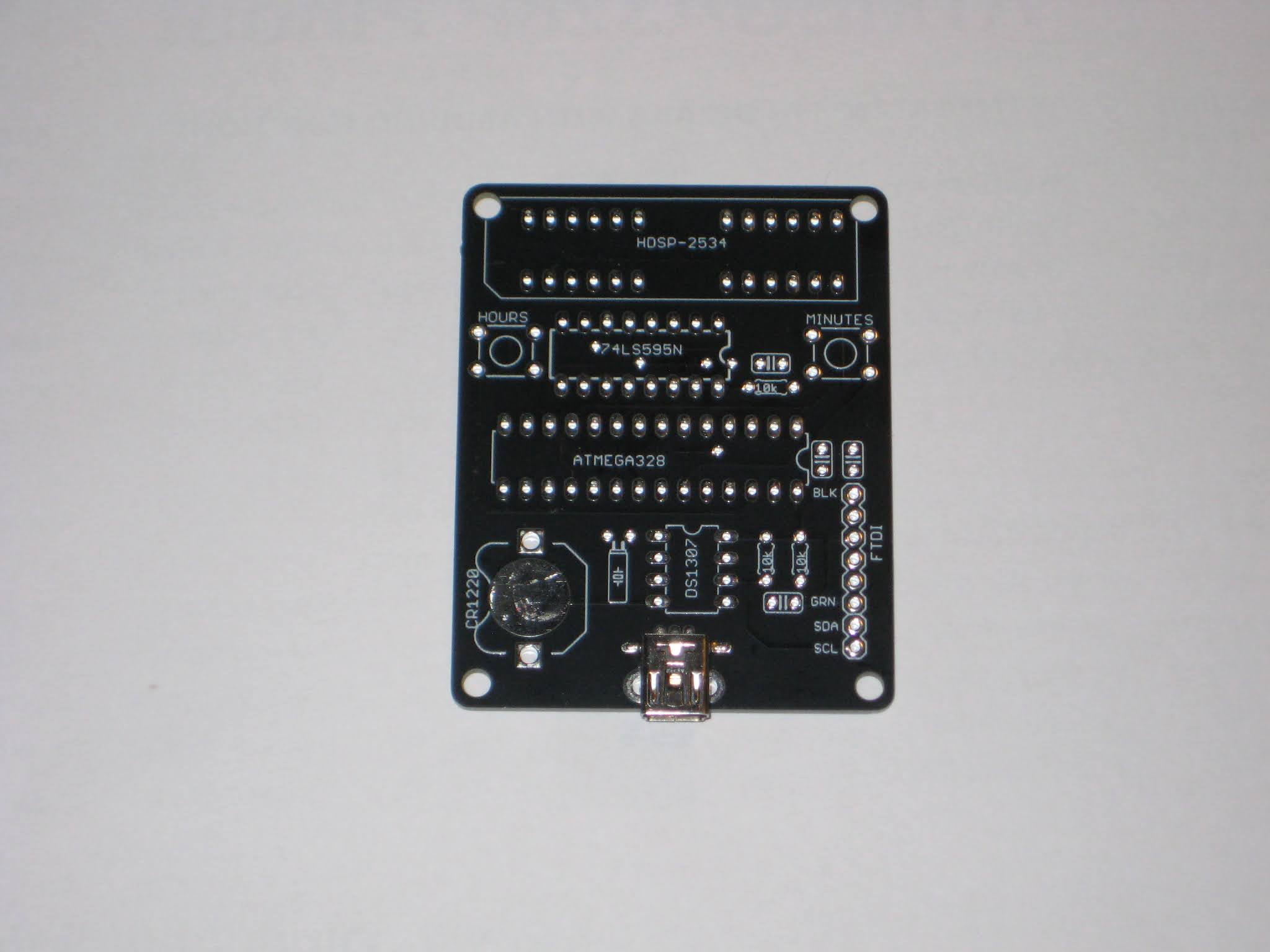
The straight USB connector can only be mounted on the bottom side of the PCB, as shown below.
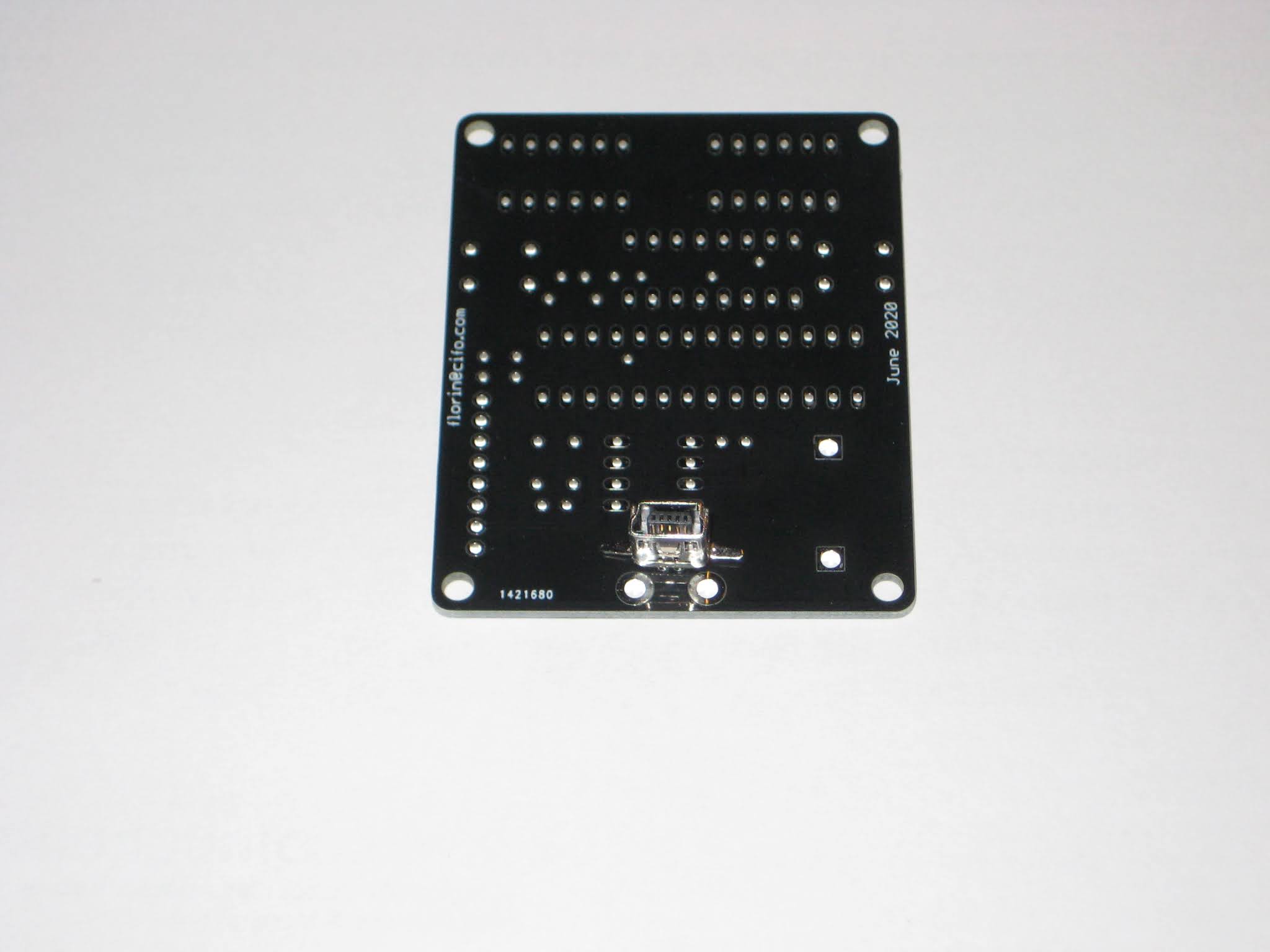
This latter configuration allows the clock to be used without any additional enclosure, with just two standoffs holding it in a vertical position, like this:

Assembly instructions for the HDSP clock kit can be found here, with the only difference being the last step, where the miniB USB connector is soldered.

[original story: Wise time with Arduino]