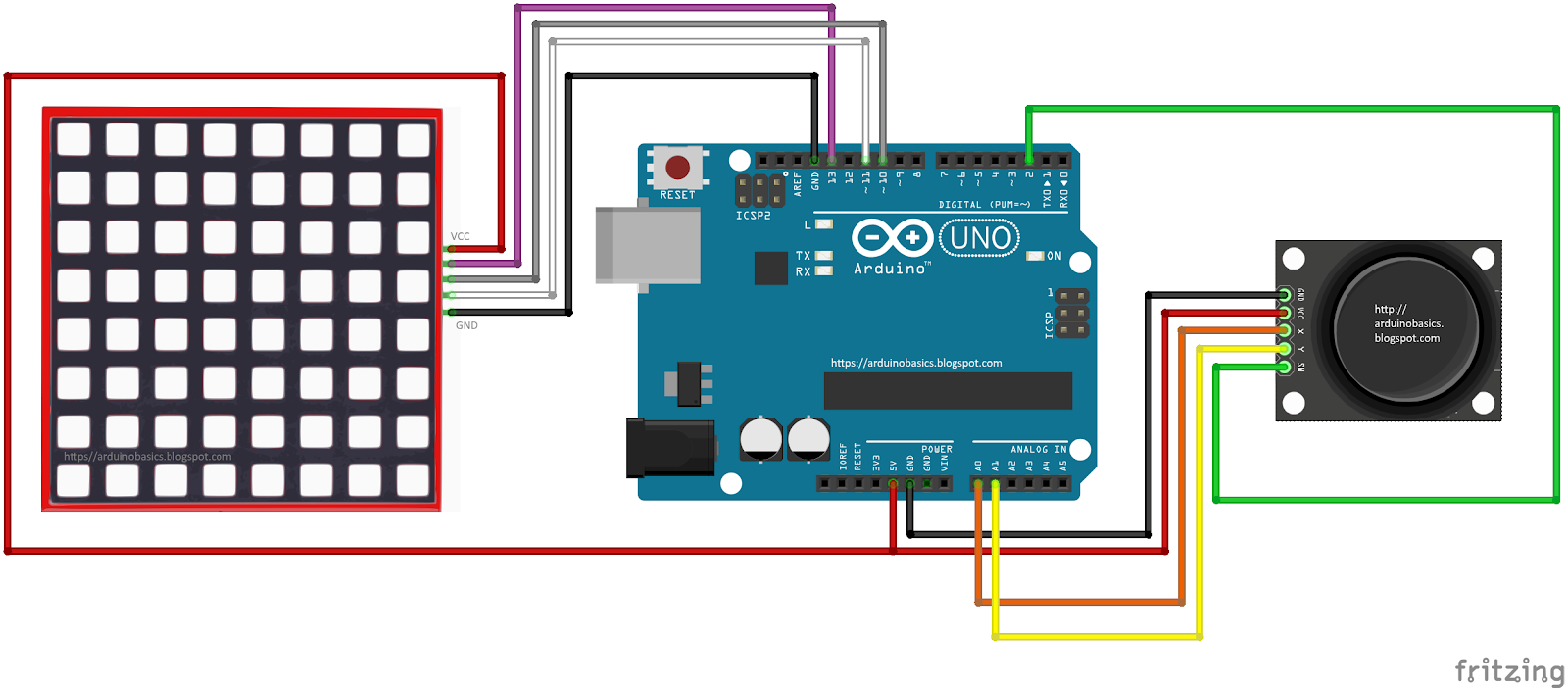
In this project, we will use a little joystick to move a pixel around an 8x8 LED matrix. The joystick has a built-in button, such that when you press down onto the joystick, the colour of the pixel will change from red to blue to green. This is a very simple project, however, controlling the matrix adds a certain level of complexity. You will need to understand binary notation and bit-shifting techniques to grasp the concept of this tutorial.
All of the parts used in this project can be obtained from digitspace.com
The SPI library is required for this project. However, this library is built into the current version of the Arduino IDE. No additional download is required. Just make sure to include it at the top of the sketch.
Arduino Code
The Arduino IDE can be downloaded from the official Arduino website: here. Copy and paste the following code into your Arduino IDE and upload it to the Arduino UNO.
As you can see from the video above, the pixel changes colour when the button is pressed. The position of the pixel relates to the position of the joystick. The lag between the joystick movement and pixel movement is minimal, and very satisfying.
Conclusion
This was a very fun and satisfying project that showcases the interaction between a joystick and a 8x8 LED matrix with the help of an Arduino UNO. This project was sponsored by the kind people at digitspace. Without their sponsorship, this tutorial would not have been possible. Please visit their website for some nice deals on Arduino related products.
If you found this tutorial helpful, please consider supporting me by buying me a virtual coffee/beer.
A Raspberry Pi Zero (W) and Arduino are very different animals, the prior has processing power and connectivity while the latter has some analog to digital converters (ADCs) and nearly real-time reactions. You can connect them to one another with a USB cable and for many projects that will happily wed the two. Beyond that, we can interface this odd couple entirely through serial, SPI, I2C, and logic-level signaling. How? Through a device by [cburgess] that is being called an Arduino shield that supports a Pi0 (W). Maybe it is a cape which interfaces with Arduino. The distinction may be moot since each board has a familiar footprint and both of them are found here.
Depending on how they are set up and programmed, one can take control over the other, or they could happily do their own thing and just exchange a little information. This board is like a marriage counselor between a Raspberry Pi and an Arduino. It provides the level-shifting so they don’t blow each other up and libraries so they can speak nicely to one another. If you want to dig a bit deeper into this one, design files and code examples are on available.
[Kerry Wong] comes across the coolest hardware, and always manages to do something interesting with it. His widget du jour is an old demo board for a digital RF attenuator chip, which can pad a signal in discrete steps according to the settings of some DIP switches. [Kerry]’s goal: forget the finger switch-flipping and bring the attenuator under Arduino control.
As usual with his videos, [Kerry] gives us a great rundown on the theory behind the hardware he’s working with. The chip in question is an interesting beast, an HMC624LP4E from Hittite, a company that was rolled into Analog Devices in 2014. The now-obsolete device is a monolithic microwave integrated circuit (MMIC) built on a gallium arsenide substrate rather than silicon, and attenuates DC to 6-GHz signals in 64 steps down to -31.5 dBm. After a functional check of the board using the DIP switches, he whipped up a quick Arduino project to control the chip with its built-in serial interface. It’s just a prototype for now, but spinning the encoder is a lot handier than flipping switches, and once this is boxed up it’ll make a great addition to [Kerry]’s RF bench.
While it’s true that your parts bin might have a few parts harvested from outdated devices of recent vintage, there’s not much to glean anymore aside from wall warts. But the 3×48-character LCD from [Kerry Wong]’s old Uniden cordless landline phone was tempting enough for him to attempt a teardown and reverse engineering, and the results were instructive.
No data sheet? No problem. [Kerry] couldn’t find anything out about the nicely backlit display, so onto the logic analyzer it went. With only eight leads from the main board to the display module, it wasn’t likely to be a parallel protocol, and the video below shows that to be the case. A little fiddling with the parameters showed the protocol was Serial Peripheral Interface, but as with other standards that aren’t exactly standardized, [Kerry] was left with enough ambiguity to make the analysis interesting. Despite a mysterious header of 39 characters, he was able in the end to drive the LCD with an Arduino, and given that these phones were usually sold as a bundle with a base and several handsets, he ought to have a nice collection of displays for the parts bin.
If you’re at all into medical hacks, you’ve doubtless noticed that the medical industry provides us with all manner of shiny toys to play with. Case in point is a heart-monitoring IC that’s so brand new, it’s not even available in all of the usual distributors yet. [Ashwin], who runs a small prototyping-supplies company, ProtoCentral, has been playing around with the new MAX30003 ECG chip, and the results look great.
The punchline is that the four-to-five dollar chip does everything for you, including analog filtering, wander removal, and even detecting the pulse rate. Using the chip is simple: you plug in two electrodes on one end, and you get the waveform data out over SPI on the other, with little or no work to do on the microprocessor side. The Arduino in the examples is just passing the SPI data straight to the laptop, with no processing going on at all.
[Ashwin] is selling these as breakout boards, but everything is open source, from the hardware to the GUI, so check it out if you’re interested in building your own. In particular, the circuit is just a voltage regulator and five volt level shifter.
Everything we know about electrocardiography projects, we learned from this presentation, and it looks like the devil is in the (many) details, so it’s nice to offload them to custom silicon whenever possible. We just think it’s awesome that we can scoop up some of the giant medical industry’s crumbs to play around with.
Adjust the phase current, crank up the microstepping, and forget about it — that’s what most people want out of a stepper motor driver IC. Although they power most of our CNC machines and 3D printers, as monolithic solutions to “make it spin”, we don’t often pay much attention to them.
In this article, I’ll be looking at the Trinamic TMC2130 stepper motor driver, one that comes with more bells and whistles than you might ever need. On the one hand, this driver can be configured through its SPI interface to suit virtually any application that employs a stepper motor. On the other hand, you can also write directly to the coil current registers and expand the scope of applicability far beyond motors.
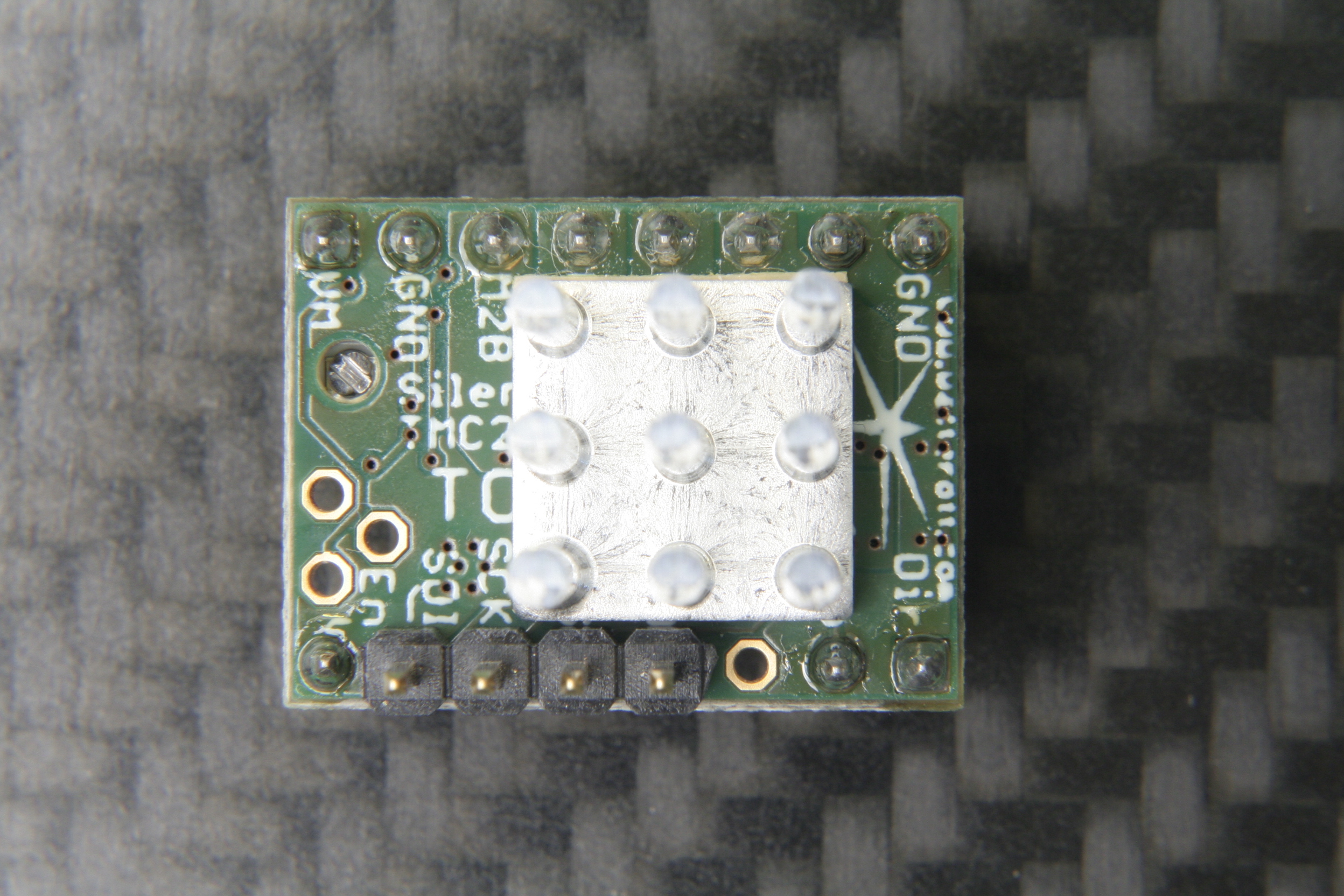
The TMC2130 SilentStepStick’s top side with SPI headers and heatsink.
Last month, we took a closer look at microstepping on common stepper driver ICs, but left out the ones that we actually want to use: the smart ones. Trinamic provides some of the smartest stepper motor drivers on the market, and since the German hacker store Watterott released their SilentStepStick breakout boards for the TMC2100 and TMC2130, they are also setting a new standard for DIY 3D printers, mills and pick-and-place robots. I recently acquired a set of both of them for my Prusa i3 3D printer, and the TMC2130 with its SPI configuration interface really caught my attention.
The TMC2130 SilentStepStick should not be confused with the — far more popular — TMC2100 variant. As the name suggests, it comes as a StepStick-compatible breakout board, and just like it’s famous sibling, features a Trinamic IC on the bottom side of the little PCB. Several vias and copper spills conduct heat away from the IC’s center pad, allowing a heatsink on the top side to effectively cool the driver.
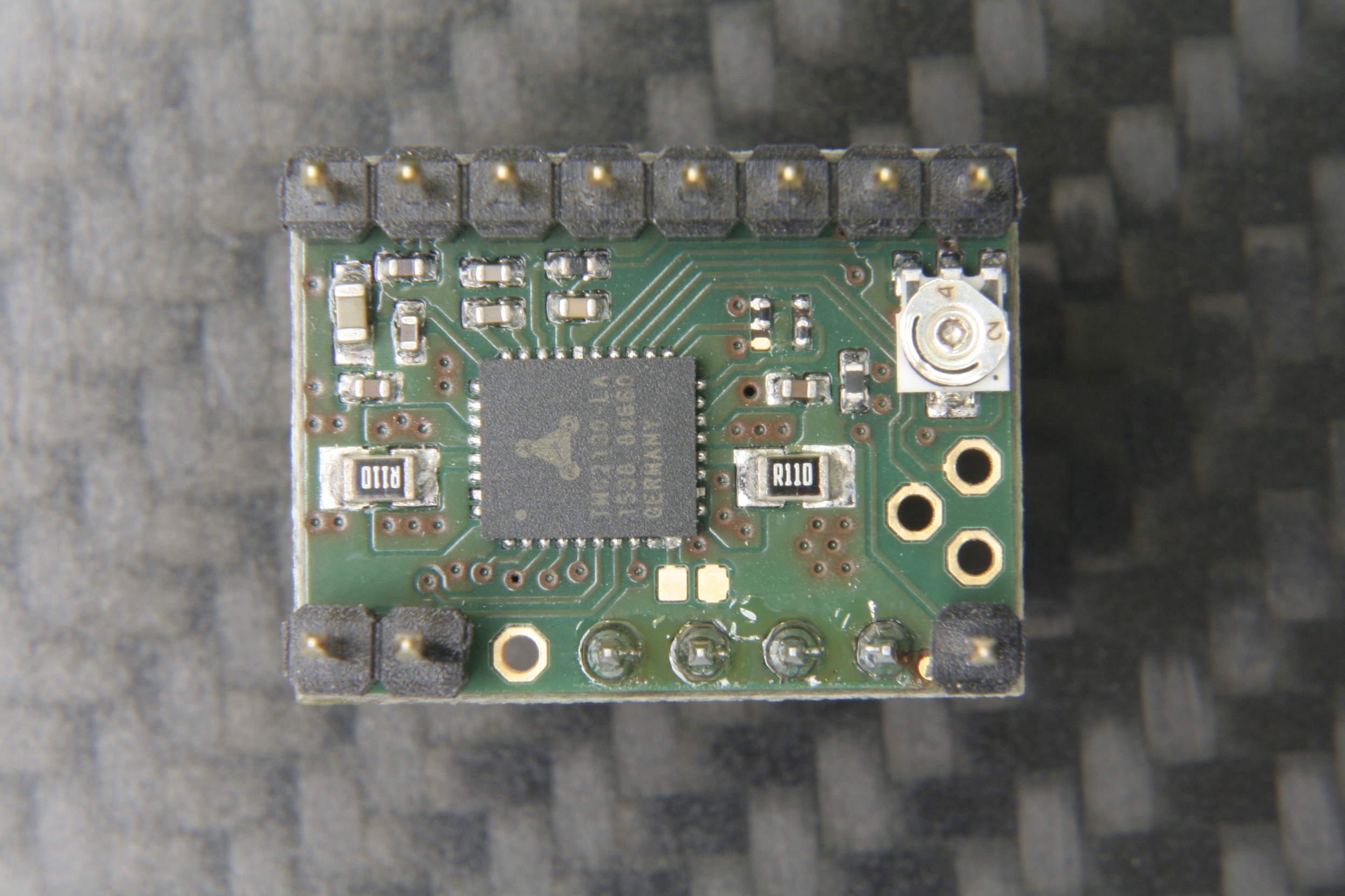
The bottom side with the stand-alone mode solder blob jumper next to the IC.
However, unlike the TMC2100, this one won’t let your motors spin right away. You’ve got two options: Hard-wire it in stand-alone mode, which practically turns it into a TMC2100, or hook up to its SPI-interface and dial in if you want your stepper motor shaken or stirred. In fact, plentiful configuration registers make the TMC2130 an extremely hackable chip, so I’m not even thinking about bridging that solder jumper on the SilentStepStick’s bottom side that activates the stand-alone mode.
First Steps
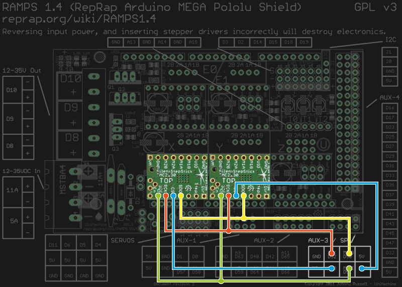
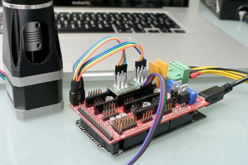
Wiring the TMC2130 to a classic RAMPS 1.4.
As said, before the driver does anything, it wants to be configured, and it’s worth mentioning that all configuration registers are naturally volatile, so if I want to use them in my 3D printer, I need to configure them as part of the printers startup routine.
The RAMPS 1.4 on my 3D printer breaks out the hardware SPI interface of the underlying Arduino through its AUX3 pin header, along with two additional digital pins (D53 and D49), which I used for the cable select signals. After crimping a cable to connect two TMC2130’s to the AUX3 header, I could start digging into the software part.
Watterott provides an example sketch, which writes a basic configuration to the driver’s registers and spins an attached stepper motor. Great stuff, but the datasheet describes 23 configuration registers waiting to be finely tuned, and 8 more to read diagnosis and status data from. So, I wrote a little Arduino library that would make the numerous configuration parameters available in a more practical way. From there, I could just include my library into the Marlin-RC7 3D printer firmware I’m using. Luckily, the current Marlin release candidate already features support for TMC26X drivers, so I could reuse some of its code to put together a Marlin fork that includes 59 of the TMC2130’s parameters in its define-based configuration files. And then, I could take the little buddies out for a spin.
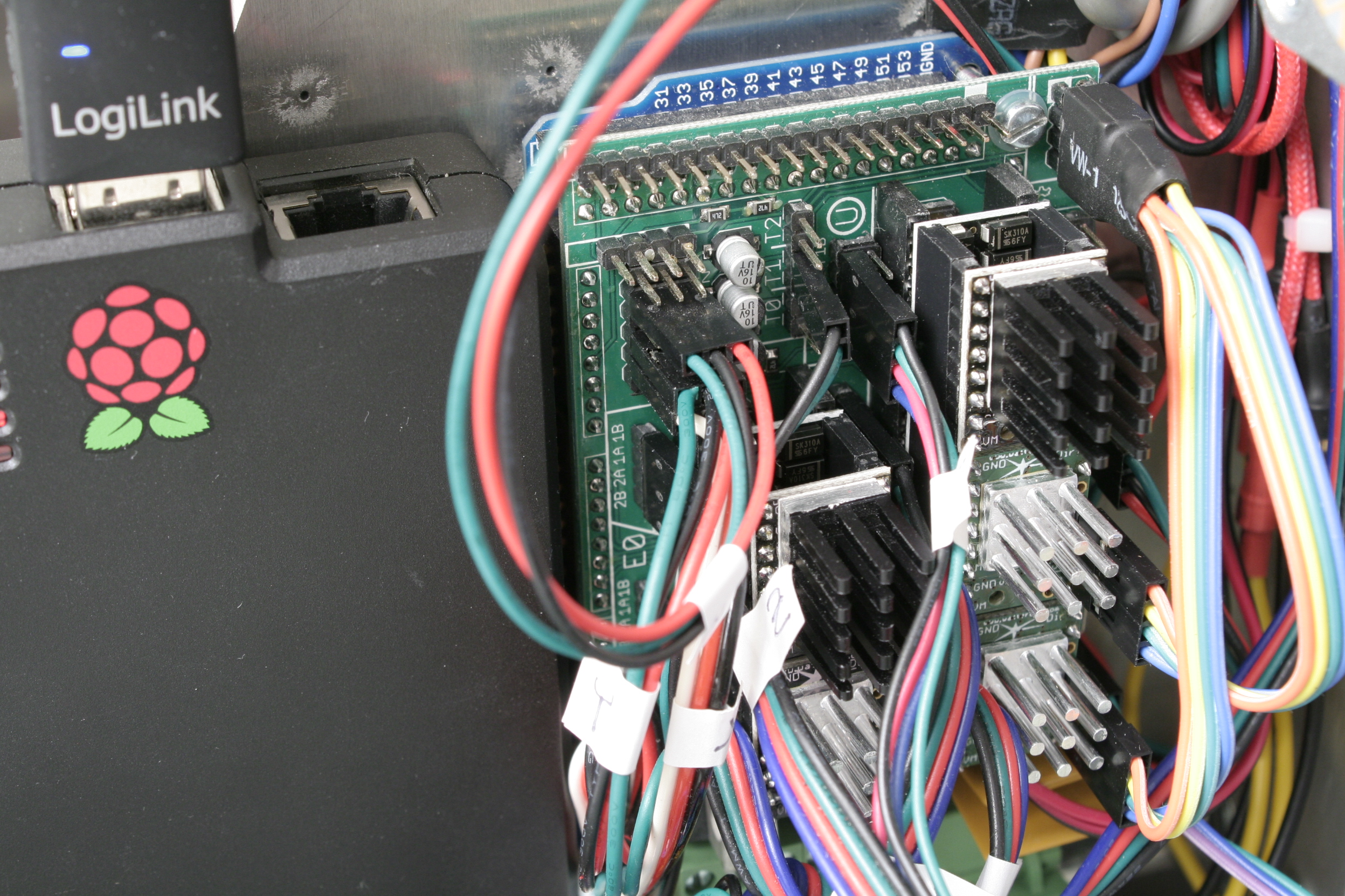
First steps on a RAMPS 1.4 on a somewhat-uino (sorry Massimo). The testing-contraption to the left is a NEMA 17 stepper motor attached to an encoder.
Taking Them For A Spin
With the hardware set up and the software working as supposed, I ran a few sanity tests: toggling parameters on and off and checking how the driver’s behavior changes during printing. Since the TMC2130 let’s you tune almost everything it’s doing, that’s a good first step that helps to eliminate some variables and picking others that are worth a deeper look. Most of the settings can be changed on the fly and mid-print, however, not all parameters can actually be safely changed while the motors are running.
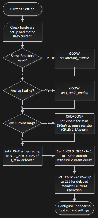
The TMC’s in service. I’m using the SPI-configurable TMC2130’s (silver heatsink) for the X- and Y- axis. The Z-axis and the extruder feature the TMC2100 (black heatsink). All of them are sitting on additional free-runner diode protection shields.An excerpt of Trinamic’s thorough quick start guide.
To actually tune the drivers for a certain application, Trinamic provides a quick start guide in the datasheet, as well as detailed information on each parameter, and on how they interact. Basically, the first step is adjusting the RMS coil current by using the onboard potentiometer on the SilentStepSticks. Then, we need to chose the analog input pin as a current scaling reference to actually make use of the potentiometer. The mentioned library lets me do this through a simple method:
myStepper.set_I_scale_analog(1); // 0: internal, 1: AIN
The running and holding current are the first real parameter that should be tuned, with the running current typically at the desired maximum current, and the holding current at 70% of this value. The delay between a stillstand and the transition from running current to holding current can be adjusted between 0 and 4 seconds, and for now, I set it to 4 seconds, practically disabling the current reduction while the 3D printer is running. The three values share one write-only register, so the corresponding method call looks like this:
and sets the running current to 100% (≙ 31), the holding current to about 70% of this value (≙ 22), and the delay between the two to 4 seconds (≙ 5).
I want torque, so I can leave stealthChop disabled. The datasheet suggests some starting values for configuring the chopper’s off time and the comparator’s blank time settings, but since it’s a key tradeoff between switching noise and torque, it makes sense to iterate through other values as well. The library methods for the two values look like this:
And finally, I need to pick a microstepping resolution and choose if I want to make use of the 256 microstep interpolation feature, covered later in this article:
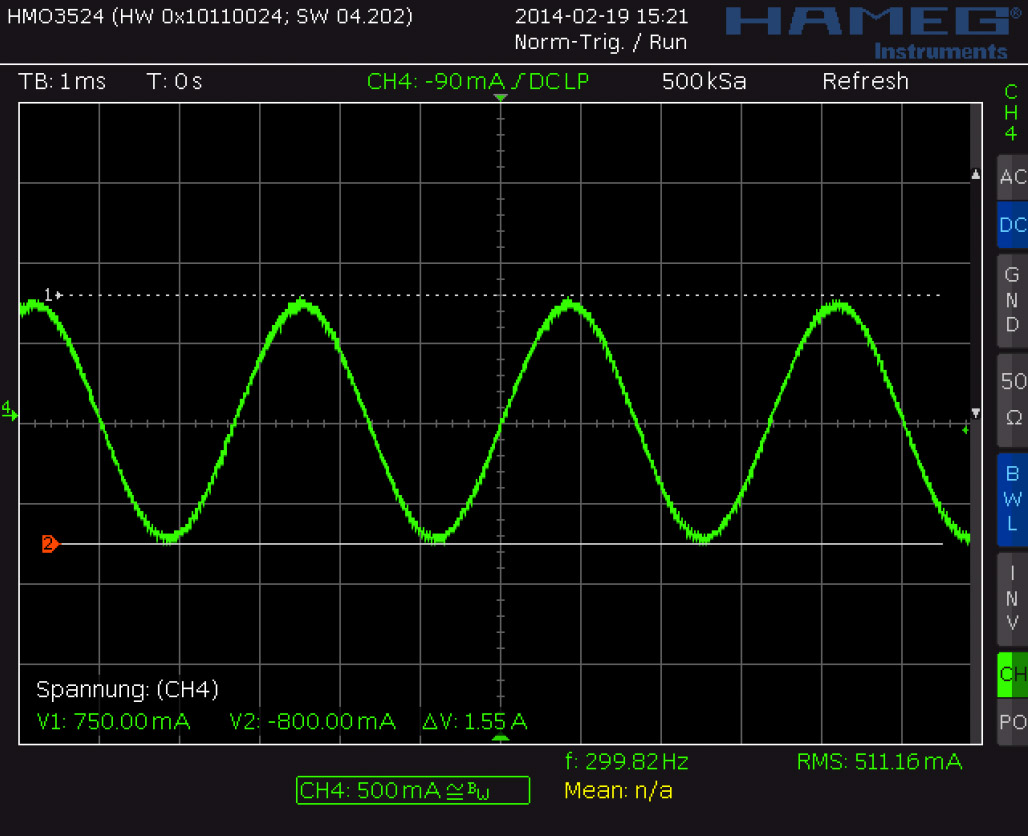
I have yet to walk through the entire tuning procedure, which includes monitoring the coil current on the scope and eliminating distortions in the zero crossing, but I’m getting a clue of the driver’s potential.
Juice
It’s maximum continuous RMS current of about 1.2 A per coil (at least in the QFN package on the SilentStepSticks) lets it look like a low-current driver, inferior to the common A4988 and DRV8825. In practice, it outperforms both of them by making intelligent use of a 2.5 A peak current margin. This gives it more than enough torque for 3D printing. I wouldn’t recommend pushing them over 0.9 A RMS though since the IC will momentarily pull more current if it needs more. For SilentStepStick users, that’s a Vref of 0.88 V. Through the SPI-interface, you can choose how much current you want to send through the motor coils when it’s spinning, and when it’s idling. You can choose after how many seconds it will start to decrease the current to a lower holding current when the motor is in standstill, and then to an even lower idling current. And, of course, you can also set it to squeeze out the maximum juice for everything.
Shifting The Gears
Where it starts getting interesting are settings like the high-velocity mode. Above a configurable velocity threshold, the driver offers you to automatically switch the chopper to a faster decay time to squeeze out some extra speed. You can also literally shift the gears by letting the driver internally switch from microstepping to full-step mode once it’s up to speed.
Microstepping
Choosing a finer microstepping resolution smoothens the stepper’s movement, reduces vibrations and sometimes even increases the positioning accuracy. However, it also multiplies the load on the microcontroller, which has to churn out 16, 32 or 256 times more step pulses per second. The TMC2130 lets you pick an input resolution between 1 and 256 microsteps per full-step, and then gives you the option of interpolating the output resolution to 256 microsteps. This allows for smooth operation even on increasingly retro 8-bit AVR motion controllers, which cannot deliver high step frequencies. Also, by configuring the TMC2130’s interface to double-edge step pulses, you can at least double the step frequency at almost no cost. Given that the modern IC still features the classic step/direction interface and even an enable pin, those few additional features actually make it a sweet drop-in upgrade for less-recent CNC and 3D printer electronics.
Noise Reduction
The TMC2130’s datasheet promises undistorted output with stealthChop.
Just like the TMC2100, the TMC2130 features two efficient and silent drive modes: spreadCycle, and stealthChop. The former delivers high torque at relatively low noise emissions, the latter one is almost inaudible but delivers a dramatically reduced torque. The flexible IC also allows you to tweak the chopper yourself to find the right balance between torque, noise, and efficiency for your application. One of the more noteworthy options in this regard is the possibility of randomizing the chopper’s off time. Since most of the audible noise is released due to dubstep the chopper busily switching the stepper motor’s coils, this option spreads the noise over a wider frequency range to subjectively silence the stepper motor.
Stall Detection
The TMC2130 notices when the motor is stalled and losing steps by measuring the motor’s back EMF. Along the way, it counts missed steps, allowing the controller to compensate for otherwise irreversible step-loss. It’s also a great way to react to obstacles rather than running into them full-force and, of course, the feature can be used as an axis endstop. Trinamic calls this feature StallGuard, and just like anything else in this motor driver, it’s highly configurable.
Direct Mode
Instead of letting the motor driver handle everything for you, you can also choose the direct mode. This mode practically turns the driver into a two-channel, bipolar constant-current source with SPI interface. You can still use it as a motor driver, but the possibilities reach far beyond that. It’s worth mentioning that the datasheet might be a bit confusing here, and the corresponding XDIRECT register actually accepts two signed 9 bit integers (not 8 bit) for each coil and operates as expected within a numeric range of, naturally, ± 254 (not ± 255) to vary the current between ± Imax/RMS..
The Takeaway
About half a year after the release of Watterott’s breakout board, the potential of smarter stepper motor drivers piqued the curiosity of the 3D printing community, but not much has happened in terms of implementation. Admittedly, it takes some effort to get them running. If you’re still busy dialing in the temperature on your 3D printer, you surely don’t want to add a few dozen new variables, but if you’re keen on getting the best out of it, the TMC2130 has a lot to offer: low-noise printing, high-speed printing, print interrupt on failure and recovery from lost steps. Because the driver IC is so hackable, it’s clearly intended to be tuned in to accommodate specific applications. Throwing it on a general purpose test bench probably won’t yield meaningful, general purpose results.
I hope you enjoyed taking a look at a smarter-than-usual stepper motor driver, as one of the new frontiers of DIY 3D printing, and as an interesting component with many other applications. If you’re thinking about experimenting with this IC or breakout board in your 3D printer, feel free to try my Marlin fork to get started. If you’re building something entirely different, the underlying Arduino library will help you out. Who else is using this part? I’ll be glad to hear about your ideas, applications, and experiences in the comments!
[Lewin] wrote in to tell us about a high speed library for Arduino Due that he helped develop which allows interfacing OLED displays that use the SSD1306 display controller, using DMA routines for faster display refresh time.
Typically, displays such as the Monochrome 1.3″ 128×64 OLED graphic display , are interfaced with an Arduino board via the SPI or I2C bus. The Adafruit_SSD1306 library written by [Limor Fried] makes it simple to use these displays with a variety of Arduinos, using either software or hardware SPI. With standard settings using hardware SPI, calls to display() take about 2ms on the Due.
[Lewin] wanted to make it faster, and the SAM3X8E on the Due seemed like it could deliver. He first did a search to find out if this was already done, but came up blank. He did find [Marek Buriak]’s library for ILI9341-based TFT screens. [Marek] used code from [William Greiman], who developed SD card libraries for the Arduino. [William] had taken advantage of the SAM3X8E’s DMA capabilities to enable faster SD card transfers, and [Marek] then adapted this code to allow faster writes to ILI9341-based screens. All [Lewin] had to do was to find the code that sent a buffer out over SPI using DMA in Marek’s code, and adapt that to the Adafruit library for the SSD1306.
There is a caveat though: using this library will likely cause trouble if you are also using SPI to interface to other hardware, since the regular SPI.h library will no longer work in tandem with [Lewin]’s library. He offers some tips on how to overcome these issues, and would welcome any feedback or testing to help improve the code. The speed improvement is substantial. Up to 4 times quicker using standard SPI clock, or 8 times if you increase SPI clock speed. The code is available on his Github repo.
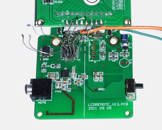
If you want to take a photograph with a professional look, proper lighting is going to be critical. [Richard] has been using a commercial lighting solution in his studio. His Lencarta UltraPro 300 studio strobes provide adequate lighting and also have the ability to have various settings adjusted remotely. A single remote can control different lights setting each to its own parameters. [Richard] likes to automate as much as possible in his studio, so he thought that maybe he would be able to reverse engineer the remote control so he can more easily control his lighting.
[Richard] started by opening up the remote and taking a look at the radio circuitry. He discovered the circuit uses a nRF24L01+ chip. He had previously picked up a couple of these on eBay, so his first thought was to just promiscuously snoop on the communications over the air. Unfortunately the chips can only listen in on up to six addresses at a time, and with a 40-bit address, this approach may have taken a while.
Not one to give up easily, [Richard] chose a new method of attack. First, he knew that the radio chip communicates to a master microcontroller via SPI. Second, he knew that the radio chip had no built-in memory. Therefore, the microcontroller must save the address in its own memory and then send it to the radio chip via the SPI bus. [Richard] figured if he could snoop on the SPI bus, he could find the address of the remote. With that information, he would be able to build another radio circuit to listen in over the air.
Using an Open Logic Sniffer, [Richard] was able to capture some of the SPI communications. Then, using the datasheet as a reference, he was able to isolate the communications that stored information int the radio chip’s address register. This same technique was used to decipher the radio channel. There was a bit more trial and error involved, as [Richard] later discovered that there were a few other important registers. He also discovered that the remote changed the address when actually transmitting data, so he had to update his receiver code to reflect this.
The receiver was built using another nRF24L01+ chip and an Arduino. Once the address and other registers were configured properly, [Richard's] custom radio was able to pick up the radio commands being sent from the lighting remote. All [Richard] had to do at this point was press each button and record the communications data which resulted. The Arduino code for the receiver is available on the project page.
[Richard] took it an extra step and wrote his own library to talk to the flashes. He has made his library available on github for anyone who is interested.
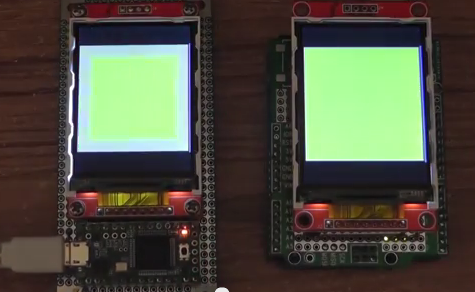
[Paul Stoffregen], known as father of the Teensy, has leveraged the Teensy 3.1’s hardware to obtain some serious speed gains with SPI driven TFT LCDs. Low cost serial TFT LCDs have become commonplace these days. Many of us have used Adafruit’s TFT LCD library to drive these displays on an Arduino. The Adafruit library gives us a simple API to work with these LCDs, and saves us from having to learn the intricacies of various driver chips.
[Paul] has turbocharged the library by using hardware available on Teensy 3.1’s 32 Freescale Kinetis K20 microcontroller. The first bump is raw speed. The Arduino’s ATmega328 can drive the SPI bus at 8MHz, while the Teensy’s Kinetis can ramp things up to 24MHz.
Speed isn’t everything though. [Paul] also used the Freescale’s 4 level FIFO to buffer transfers. By using a “Write first, then block until the FIFO isn’t full” algorithm, [Paul] ensured that new data always gets to the LCD as fast as possible.
Another huge bump was SPI chip select. The Kinetis can drive up to 5 SPI chip select pins from hardware. The ATmega328 doesn’t support chip selects. so they must be implemented with GPIO pins, which takes even more time.
The final result is rather impressive. Click past the break to see the ATmega based Arduno race against the Kinetis K20 powered Teensy 3.1.
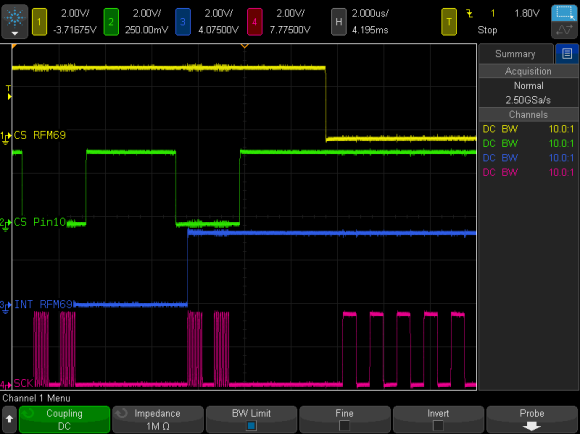
To prevent data corruption when using multiple SPI devices on the same bus, care must be taken to ensure that they are only accessed from within the main loop, or from the interrupt routine, never both. Data corruption can happen when one device is chip selected in the main loop, and then during that transfer an interrupt occurs, chip selecting another device. The original device now gets incorrect data.
For the last several weeks, [Paul] has been working on a new Arduino SPI library, to solve these types of conflicts. In the above scenario, the new library will generate a blocking SPI transaction, thus allowing the first main loop SPI transfer to complete, before attempting the second transfer. This is illustrated in the picture above, the blue trace rising edge is when the interrupt occurred, during the green trace chip select. The best part, it only affects SPI, your other interrupts will still happen on time. No servo jitter!
This is just one of the new library features, check out the link above for the rest. [Paul] sums it up best: “protects your SPI access from other interrupt-based libraries, and guarantees correct setting while you use the SPI bus”.


