Posts with «ssd1306» label

Arduino UNO R4 WiFi: A Guide to Sensors and Displays

We bring the connections of the STEMMA QT/Qwiic connector available on the Arduino UNO R4 WiFi to the outside, using a board that can host I²C-Bus devices and can be daisy-chained with others of the same type.

Among the new features introduced by the Arduino UNO R4, the WiFi version stands out with a small interface connector called STEMMA QT/Qwiic. For form-factor compatibility reasons, this connection did not find a place in the traditional headers compatible with UNO boards, but it is located on the left side of the ICSP.

The connector makes an I²C-Bus accessible according to the pinout shown in Fig. 1, which can be used to manage external devices such as displays, sensors, etc., as long as they support I²C communication.

Fig. 1 Position of the STEMMA QT/Qwiic connector on the Arduino R4 WiFi board.

The SCL and SDA lines, unlike what happens in previous Arduino boards based on Atmel processors (where they were shared with pins A4 and A5 of the standard Arduino header), are connected to a second (secondary) I²C bus. In fact, the Renesas chip used in the R4 makes two distinct I²C buses available. The second one must be managed, however, by calling the specific object Wire1, as will be explained later in this article. The connection was introduced in the Arduino R4 (only in the WiFi version) to quickly connect Sparkfun standard breakout boards to it, since the connector used, a 4-pin single-in-line PCB connector, is the one adopted by Sparkfun boards. Qwiic is an ecosystem of breakout modules and development boards equipped with a so-called Qwiic connector, and it combines the flexibility of I²C with the ease of use of ready-made compatible cables available on the market, making it simple to manage a chain of I²C-Bus devices through a single cable. In practice, this means that wiring Qwiic devices is as simple as connecting them in series, and that’s it. To facilitate the connection and provide physical support for the breakout boards, instead of leaving them “flying,” we thought of designing and proposing a small adapter board that has two connectors compatible with the STEMMA QT/Qwiic standard, creating a pass-through connection that allows interfacing devices on the board itself, but also using the I²C bus to connect other devices. The I²C-Bus connections are distributed on our board in rows of pads where you can insert strips to connect and mechanically support breakout boards. Everything will be clearer by analyzing the project’s electrical schematic, which you can find on this page.

Electrical schematic

Electrical schematic of the adapter board.

As you can see, it is something very simple, which in fact has no electronics but simply creates a series of electrical interconnections, making a pass-through I²C-Bus connection between input and output through the two 4-pin Sparkfun-type connectors, and which has four rows of four pads at 2.54 mm pitch, ready for soldering female strips or pin strips for sensors and various devices. Note that the layout on the printed circuit board provides that the rows of pads have contacts arranged differently from one side to the opposite one: we wanted this to allow mounting boards and especially displays (since the problem occurs, for example, with small OLEDs) that have a different arrangement of Vcc and GND, as well as SDA and SCL. Through the STEMMA QT/Qwiic connector, the power needed for the breakout boards to operate is taken from the Arduino UNO R4 board, thus achieving independent operation of the devices connected to Arduino. As you can see, the circuit is essential and basically only serves to carry connections. The nice thing is that having two JST connectors makes it possible to daisy-chain numerous I²C-Bus interface devices on multiple boards, since the one connected to the Arduino R4 can in turn be connected to a second board, the latter to a third, and so on, to host more elements. For the interconnection between the Arduino R4 and our board, and between multiple adapter boards, you can use a pre-wired cable with a 4-pin JST connector at each end, 1 mm pitch, available at Futura Elettronica. The adapter board we propose here can also be purchased ready-made from [Futura Elettronica](www.futurashop.it) with product code FT1732M.

Construction and use

Photo of the adapter board.

The small adapter board described here can be easily prepared by photoengraving once you have the two copper-side traces, however, given its really low cost, it is possible and convenient to buy it ready-made. To explain how to use it, we propose a basic application that involves acquiring information from a breakout board for barometric pressure and ambient temperature sensors, then displaying it on a small 0.96″ monochrome OLED display based on the SSD1306 controller; clearly, we are referring to two devices equipped with an I²C-Bus interface. The Arduino R4 WiFi connector to use is the one detailed in Fig. 2. To use a Bosch BME280 sensor on a breakout board with the Arduino R4 and the STEMMA standard, you must mount the small breakout board using the appropriate pin strips and following the intended orientation (Fig. 3 can help you, where you can also see in which position to mount it); be careful that if you do not respect the indicated position and orientation, the small board can be irreparably damaged.

Fig. 2 The JST connector for the Qwiic STEMMA connection to be used to connect our board.
Fig. 3 The adapter with an I²C BME280 sensor on a breakout board.

This is because, as mentioned, the rows of I²C-Bus pads inside the printed circuit board are arranged differently depending on which side they are on, to allow mounting all breakout boards available on the market, equipped with 2.54 mm pitch strip connections. On a second FT1732M adapter board, you must mount the small OLED display, which is a standard type and, more precisely, the one sold by Futura Elettronica with the code OLEDGVSCSD; the device must be applied as shown in Fig. 4 after soldering a 4-pin pin-strip to it and using the row of pads whose contacts are arranged as follows: GND, VCC, SCL, SDA.

Fig. 4 The STEMMA QT/Qwiic adapter with the 0.96-inch display module attached.

To implement communication with the BME280 breakout, you must first load the Adafruit_BME280 library into the Arduino IDE; to do this, open the IDE, go to the Sketch menu, and issue the Include Library > Manage Libraries… command. At this point, search for “Adafruit BME280” in the search bar and install the corresponding library. Installation can also be done from a .zip file containing the library, using the appropriate menu command. Then, from the File menu, you can issue the Examples command and load the “BME280_I2C” example; once the sketch is displayed, load it onto the board (the IDE must already have the UNO R4 WiFi among the boards available in the Tools > Board… submenu) and run it, opening the Serial Monitor to view the pressure and temperature data read by the sensor. Note that the Arduino UNO R4 WiFi has two I²C buses and that the Qwiic connector is connected to the secondary one, so you must use Wire1. In most cases, you will be able to select the Wire1 object during library initialization with this code snippet:

Wire1.begin();
libraryName.begin( Wire1 );

Our test sketch

To test the adapter board and the STEMMA Qwiic connection, we wrote for you the simple sketch proposed in Listing 1, which, in association with the breakout board based on BME280 and the OLED display, implements an essential weather station capable of displaying atmospheric pressure and ambient temperature.

To work, the sketch includes the Wire.h, Adafruit Sensor.h, BME280.h, GFX.h, and SSD1306.h libraries, as well as ArduinoGraphics.h and Arduino_LED_Matrix.h to manage the display; in particular, SSD1306.h handles the controller integrated into the OLED display module. In the Setup, the Serial Monitor is initialized for communication at 115200 baud, and then commands are issued to use Wire1, with the instructions:

// Qwiic
Wire1.begin();
Wire1.setClock(100000);
Wire1.setTimeout(1000);

that will be used to make the Arduino UNO R4 communicate with the display and the BPM280 sensor through the Qwiic / STEMMA interface. Once this is done, the I²C-Bus OLED display and the sensor are initialized, then you start acquiring samples of the quantities detected by the latter, sending the result to the display at the corresponding I²C-Bus address. These two operations are repeated in a loop, with a delay time of 20 ms. Note that using the I²C-Bus implies defining the address of the two peripherals in the firmware; in this regard, it should be said that the BME280 breakout typically has address 0x76, which is the default in our sketch; if the query fails and no data appears on the display, it is advisable to change the I²C address in the following line of code:

uint8_t BME_ADDR = 0x76;

replacing 0x76 with 0x77, because breakouts with this preset address also exist. As for the OLED display used in this example, it has an I²C-Bus address of 0x3C, which is fixed and does not vary from manufacturer to manufacturer, because it is defined in the controller chip.

Conclusions

Well, with this we have finished and we leave you to your practical experiments with the Arduino UNO R4 and its Qwiic connection. The application proposed here is one of the many examples of use and employs one board for each I²C-Bus device; however, each one can host, depending on size, multiple breakouts, and remember that the STEMMA/Qwiic connector also supports more than two adapter boards, depending on the current that can be supplied to the bus.

The post Arduino UNO R4 WiFi: A Guide to Sensors and Displays appeared first on Open Electronics.
Tutorial – Using the 0.96″ 128 x 64 Graphic I2C OLED Displays with Arduino

The purpose of this guide is to have an SSD1306-based OLED display successfully operating with your Arduino, so you can move forward and experiment and explore further types of operation with the display.

This includes installing the Arduino library, making a succesful board connection and running a demonstration sketch. So let’s get started!

Connecting the display to your Arduino

The display uses the I2C data bus for communication, and is a 5V and 3.3V-tolerant board.

Arduino Uno to Display

GND ---- GND (GND)
5V/3.3V- Vcc (power supply, can be 3.3V or 5V)
A5 ----- SCL (I2C bus clock)
A4 ----- SDA (I2C bus data)

I2C pinouts vary for other boards. Arduino Leonard uses D2/D3 for SDA and SCL or the separate pins to the left of D13. Arduino Mega uses D20/D21 for SDA and SCL. If you can’t find your I2C pins on other boards, ask your display supplier.

Installing the Arduino library

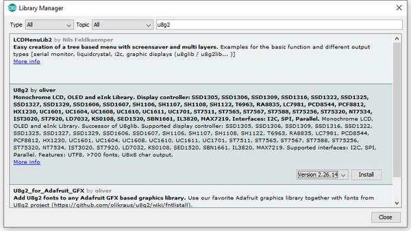
To install the library – simply open the Arduino IDE and select Manage Libraries… from the Tools menu. Enter “u8g2” in the search box, and after a moment it should appear in the results as shown in the image below. Click on the library then click “Install”:

After a moment the library will be installed and you can close that box.

Now it’s time to check everything necessary is working. Open a new sketch in the IDE, then copy and paste the following sketch into the IDE:

// Display > https://pmdway.com/products/0-96-128-64-graphic-oled-displays-i2c-or-spi-various-colors

#include <Arduino.h>
#include <U8x8lib.h>

#ifdef U8X8_HAVE_HW_SPI
#include <SPI.h>
#endif
#ifdef U8X8_HAVE_HW_I2C
#include <Wire.h>
#endif

  U8X8_SSD1306_128X64_NONAME_HW_I2C u8x8(/* reset=*/ U8X8_PIN_NONE);   

/*
  This example will probably not work with the SSD1606, because of the
  internal buffer swapping
*/

void setup(void)
{
  /* U8g2 Project: KS0108 Test Board */
  //pinMode(16, OUTPUT);
  //digitalWrite(16, 0);  

  /* U8g2 Project: Pax Instruments Shield: Enable Backlight */
  //pinMode(6, OUTPUT);
  //digitalWrite(6, 0); 

  u8x8.begin();
  //u8x8.setFlipMode(1);
}

void pre(void)
{
  u8x8.setFont(u8x8_font_amstrad_cpc_extended_f);    
  u8x8.clear();

  u8x8.inverse();
  u8x8.print(" U8x8 Library ");
  u8x8.setFont(u8x8_font_chroma48medium8_r);  
  u8x8.noInverse();
  u8x8.setCursor(0,1);
}

void draw_bar(uint8_t c, uint8_t is_inverse)
{ 
  uint8_t r;
  u8x8.setInverseFont(is_inverse);
  for( r = 0; r < u8x8.getRows(); r++ )
  {
    u8x8.setCursor(c, r);
    u8x8.print(" ");
  }
}

void draw_ascii_row(uint8_t r, int start)
{
  int a;
  uint8_t c;
  for( c = 0; c < u8x8.getCols(); c++ )
  {
    u8x8.setCursor(c,r);
    a = start + c;
    if ( a <= 255 )
      u8x8.write(a);
  }
}

void loop(void)
{
  int i;
  uint8_t c, r, d;
  pre();
  u8x8.print("github.com/");
  u8x8.setCursor(0,2);
  u8x8.print("olikraus/u8g2");
  delay(2000);
  u8x8.setCursor(0,3);
  u8x8.print("Tile size:");
  u8x8.print((int)u8x8.getCols());
  u8x8.print("x");
  u8x8.print((int)u8x8.getRows());
  
  delay(2000);
   
  pre();
  for( i = 19; i > 0; i-- )
  {
    u8x8.setCursor(3,2);
    u8x8.print(i);
    u8x8.print("  ");
    delay(150);
  }
  
  draw_bar(0, 1);
  for( c = 1; c < u8x8.getCols(); c++ )
  {
    draw_bar(c, 1);
    draw_bar(c-1, 0);
    delay(50);
  }
  draw_bar(u8x8.getCols()-1, 0);

  pre();
  u8x8.setFont(u8x8_font_amstrad_cpc_extended_f); 
  for( d = 0; d < 8; d ++ )
  {
    for( r = 1; r < u8x8.getRows(); r++ )
    {
      draw_ascii_row(r, (r-1+d)*u8x8.getCols() + 32);
    }
    delay(400);
  }

  draw_bar(u8x8.getCols()-1, 1);
  for( c = u8x8.getCols()-1; c > 0; c--)
  {
    draw_bar(c-1, 1);
    draw_bar(c, 0);
    delay(50);
  }
  draw_bar(0, 0);

  pre();
  u8x8.drawString(0, 2, "Small");
  u8x8.draw2x2String(0, 5, "Scale Up");
  delay(3000);

  pre();
  u8x8.drawString(0, 2, "Small");
  u8x8.setFont(u8x8_font_px437wyse700b_2x2_r);
  u8x8.drawString(0, 5, "2x2 Font");
  delay(3000);

  pre();
  u8x8.drawString(0, 1, "3x6 Font");
  u8x8.setFont(u8x8_font_inb33_3x6_n);
  for(i = 0; i < 100; i++ )
  {
    u8x8.setCursor(0, 2);
    u8x8.print(i);      // Arduino Print function
    delay(10);
  }
  for(i = 0; i < 100; i++ )
  {
    u8x8.drawString(0, 2, u8x8_u16toa(i, 5)); // U8g2 Build-In functions
    delay(10);    
  }

  pre();
  u8x8.drawString(0, 2, "Weather");
  u8x8.setFont(u8x8_font_open_iconic_weather_4x4);
  for(c = 0; c < 6; c++ )
  {
    u8x8.drawGlyph(0, 4, '@'+c);
    delay(300);
  }
  

  pre();
  u8x8.print("print \\n\n");
  delay(500);
  u8x8.println("println");
  delay(500);
  u8x8.println("done");
  delay(1500);

  pre();
  u8x8.fillDisplay();
  for( r = 0; r < u8x8.getRows(); r++ )
  {
    u8x8.clearLine(r);
    delay(100);
  }
  delay(1000);
}

Your display should go through the demonstration of various things as shown in the video below:

If the display did not work – you may need to manually set the I2C bus address. To do this, wire up your OLED then run this sketch (open the serial monitor for results). It’s an I2C scanner tool that will return the I2C bus display. 

Then use the following line in void setup():

u8x8.setI2CAddress(address)

Replace u8x8 with your display reference, and address with the I2C bus address (for example. 0x17).

Moving on…

By now you have an idea of what is possible with these great-value displays.

Now your display is connected and working, it’s time to delve deeper into the library and the various modes of operations. There are three, and they are described in the library documentation – click here to review them. 

Whenever you use one of the three modes mentioned above, you need to use one of the following constructor lines:

U8G2_SSD1306_128X64_NONAME_F_HW_I2C u8g2(U8G2_R0, /* reset=*/ U8X8_PIN_NONE); // full buffer mode

U8X8_SSD1306_128X64_NONAME_HW_I2C u8x8(/* reset=*/ U8X8_PIN_NONE); // 8x8 character mode

U8G2_SSD1306_128X64_NONAME_1_HW_I2C u8g2(U8G2_R0, /* reset=*/ U8X8_PIN_NONE); // page buffer mode

Match the mode you wish to use with one of the constructors above. For example, in the demonstration sketch you ran earlier, we used the 8×8 character mode constructor in line 14.

Where to from here?

Now it’s time for you to explore the library reference guide which explains all the various functions available to create text and graphics on the display, as well as the fonts and so on. These can all be found on the right-hand side of the driver wiki page.

This post brought to you by pmdway.com – everything for makers and electronics enthusiasts, with free delivery worldwide.

To keep up to date with new posts at tronixstuff.com, please subscribe to the mailing list in the box on the right, or follow us on twitter @tronixstuff.

Tronixstuff 29 Aug 08:38

Push it to the Limit: SSD1306 at 150 FPS

A good deal of the projects we cover here at Hackaday are not, in the strictest sense, practical endeavors. If we required that everything which graced our digital pages had a clear end result, the site would be in a rather sad state of affairs. Sometimes it’s enough just to do something for the challenge of it. But more often than not, you’ll learn something in the process which you can use down the line.

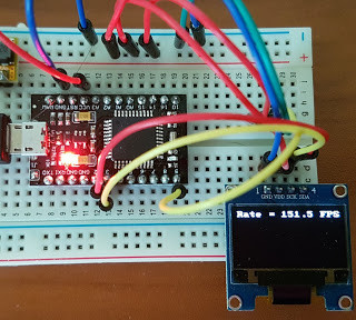
That’s precisely what pushed [Laurence Bank] to see how well he could optimize the frame rate on the popular SSD1306 OLED display. After several iterations of his code, he was able to achieve a blistering 151.5 FPS, with apparently still some room for improvement if he’s feeling up to the challenge. But considering his first attempt was only running at 5.5 FPS, we’d say he’s already more than earned his hacker cred on this one.

A few different tricks were used to achieve such incredible performance gains. To start with, while the official I2C specification says you’re supposed to wait for an acknowledgment back from the device when communicating with it, [Laurence] realized the SSD1306 didn’t actually care. He could continuously blast commands at the display without bothering to wait for an acknowledgment. He admits there are problems with this method, but you can’t argue with the results.

To really wring all the performance out of the system he could, [Laurence] donned his Assembly Cap and examined how the Arduino IDE compiler was interpreting his code. He identified a few areas where changing his C code would force the compiler to generate faster output. He notes that this wouldn’t normally be required when working with more advanced compilers, but that the Arduino toolchain needs its hand held occasionally.

This isn’t the first time we’ve seen somebody try and push more pixels through the very same OLED display, and it’s interesting to see the two very different approaches to the same goal.

High Speed SSD1306 Library

[Lewin] wrote in to tell us about a high speed library for Arduino Due that he helped develop which allows interfacing OLED displays that use the SSD1306 display controller, using DMA routines for faster display refresh time.

Typically, displays such as the Monochrome 1.3″ 128×64 OLED graphic display , are interfaced with an Arduino board via the SPI or I2C bus. The Adafruit_SSD1306 library written by [Limor Fried] makes it simple to use these displays with a variety of Arduinos, using either software or hardware SPI. With standard settings using hardware SPI, calls to display() take about 2ms on the Due.

[Lewin] wanted to make it faster, and the SAM3X8E on the Due seemed like it could deliver. He first did a search to find out if this was already done, but came up blank. He did find [Marek Buriak]’s library for ILI9341-based TFT screens. [Marek] used code from [William Greiman], who developed SD card libraries for the Arduino. [William] had taken advantage of the SAM3X8E’s DMA capabilities to enable faster SD card transfers, and [Marek] then adapted this code to allow faster writes to ILI9341-based screens. All [Lewin] had to do was to find the code that sent a buffer out over SPI using DMA in Marek’s code, and adapt that to the Adafruit library for the SSD1306.

There is a caveat though: using this library will likely cause trouble if you are also using SPI to interface to other hardware, since the regular SPI.h library will no longer work in tandem with [Lewin]’s library. He offers some tips on how to overcome these issues, and would welcome any feedback or testing to help improve the code. The speed improvement is substantial. Up to 4 times quicker using standard SPI clock, or 8 times if you increase SPI clock speed. The code is available on his Github repo.


Filed under: Arduino Hacks