Posts with «rf» label

Fail of the Week: The Arduino Walkie That Won’t Talkie

There’s something seriously wrong with the Arduino walkie-talkie that [GreatScott!] built.

The idea is simple: build a wireless intercom so a group of motor scooter riders can talk in real-time. Yes, such products exist commercially, but that’s no fun at all. With a little ingenuity and a well-stocked parts bin, such a device should be easy to build on the cheap, right?

Apparently not. [GreatScott!] went with an Arduino-based design, partly due to familiarity with the microcontroller but also because it made the RF part of the project seemingly easier due to cheap and easily available nRF24 2.4 GHz audio streaming modules. Everything seems straightforward enough on the breadboard – an op-amp to boost the signal from the condenser mic, a somewhat low but presumably usable 16 kHz sampling rate for the ADC. The radio modules linked up, but the audio quality was heavily distorted.

[GreatScott!] assumed that the rat’s nest of jumpers on the breadboard was to blame, so he jumped right to a PCB build. It’s a logical step, but it seems like it might be where he went wrong, because the PCB version was even worse. We’d perhaps have isolated the issue with the breadboard circuit first; did the distortion come from the audio stage? Or perhaps did the digitization inject some distortion? Or could the distortion be coming from the RF stage? We’d want to answer a few questions like that before jumping to a final design.

We love that [GreatScott!] has no issue with posting his failures – we’ve covered his suboptimal CPU handwarmer, and his 3D-printed BLDC motor stator was a flop too. It’s always nice to post mortem these things to avoid a similar fate.

Digital Attenuator Goes from Manual to Arduino Control

[Kerry Wong] comes across the coolest hardware, and always manages to do something interesting with it. His widget du jour is an old demo board for a digital RF attenuator chip, which can pad a signal in discrete steps according to the settings of some DIP switches. [Kerry]’s goal: forget the finger switch-flipping and bring the attenuator under Arduino control.

As usual with his videos, [Kerry] gives us a great rundown on the theory behind the hardware he’s working with. The chip in question is an interesting beast, an HMC624LP4E from Hittite, a company that was rolled into Analog Devices in 2014. The now-obsolete device is a monolithic microwave integrated circuit (MMIC) built on a gallium arsenide substrate rather than silicon, and attenuates DC to 6-GHz signals in 64 steps down to -31.5 dBm. After a functional check of the board using the DIP switches, he whipped up a quick Arduino project to control the chip with its built-in serial interface. It’s just a prototype for now, but spinning the encoder is a lot handier than flipping switches, and once this is boxed up it’ll make a great addition to [Kerry]’s RF bench.

If this video puts you in an RF state of mind, check out some of [Kerry]’s other videos, like this one about temperature-compensated crystal oscillators, or the mysteries of microwave electronics.

High-Effort Streaming Remote for Low-Effort Bingeing

There’s no limit to the amount of work some people will put into avoiding work. For instance, why bother to get up from your YouTube-induced vegetative state to adjust the volume when you can design and build a remote to do it for you?

Loath to interrupt his PC streaming binge sessions, [miroslavus] decided to take matters into his own hands. When a commercially available wireless keyboard proved simultaneously overkill for the job and comically non-ergonomic, he decided to build a custom streaming remote. His recent microswitch encoder is prominently featured and provides scrolling control for volume and menu functions, and dedicated buttons are provided for play controls. The device reconfigures at the click of a switch to support Netflix, which like YouTube is controlled by sending keystrokes to the PC through a matching receiver. It’s a really thoughtful design, and we’re sure the effort [miroslavus] put into this will be well worth the dozens of calories it’ll save in the coming years.

A 3D-printed DIY remote is neat, but don’t forget that printing can also save a dog-chewed remote and win the Repairs You Can Print contest.

Prextron CHAIN BLOCKS - Arduino Nano controlled Ultrasonic sensor that switches a motor wirelessly using 433MHz RF modules and a relay board.


Description

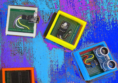
In this tutorial, I will be evaluating Prextron CHAIN blocks – a new system that allows you to connect your sensors and actuators to an Arduino NANO using clever 3D-printed prototyping boards that can be stacked sideways. This very modular system makes it easy to connect, disconnect and replace project components, and eliminate the “rats nest of wires” common to many advanced Arduino projects. CHAIN BLOCKS are open, which means that you can incorporate any of your sensors or actuators to these prototyping boards, and you can decide which specific pin on Arduino you plan to use. The CHAIN BLOCK connections prevent or reduce common connection mistakes, which make them ideal for class-room projects and learning activities.

I am going to set up a project to put these CHAIN BLOCKs to the test:
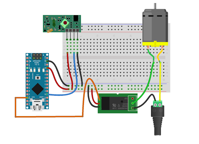
When I place my hand in-front of an Ultrasonic sensor, the Arduino will transmit a signal wirelessly to another Arduino, and consequently turn on a motor.


Parts Required:

You need the following Prextron Chain Blocks


Please note: You may need to solder the module wires to the CHAIN BLOCK protoboard.


Arduino Libraries and IDE

This project does not use any libraries. However, you will need to upload Arduino code to the Arduino. For this you will need the Arduino IDE which can be obtained from the official Arduino website:
https://www.arduino.cc/en/main/software


ARDUINO CODE: RF Transmitter


ARDUINO CODE: RF Receiver


Fritzing diagrams for Transmitter


Fritzing diagrams for Receiver


Concluding comments

The purpose of this project was to evaluate Prextron CHAIN BLOCKs and put them to the test. Here is what I thought of CHAIN BLOCKS at the time of evaluation. Some of my points mentioned below may no longer apply to the current product. It may have evolved / improved since then. So please take that into consideration


What I liked about Chain Blocks

  • The design is simple, the product is simple.
  • Once the Chain Blocks were all assembled, they were very easy to connect to each other.
  • I can really see the benefit of Chain Blocks in a teaching environment, because it simplifies the connection process, and reduces connection mixups.
  • It was good to see that the blocks come in different colours, which means that you can set up different colour schemes for different types of modules.
  • You can incorporate pretty much any sensor or Actuator into the Chain block which is very appealing.
  • You also have the flexibility of choosing which pins you plan to use on the Arduino.
  • Projects look a lot neater, because you no longer have the rats nest of wires.
  • The Blocks lock into each other which means that they are much easier to transport/carry.


What I did not like about Chain Blocks

  • In most cases, the Chain Block protoboard lanes were not numbered, which increased the chances of making mistakes when soldering
  • The need to solder modules to the protoboard, may be a discouragement for some people.
  • I would have liked a choice of different size Chain blocks. Some of the sensors did not fit nicely into the Square blocks.
  • Prextron really need to work on their website if they plan to get serious with this product: Webpage has incomplete functionality or irrelevant links etc etc.


Thank you very much to Prextron for providing the CHAIN BLOCKS used in this tutorial, and allowing me to try out their product. If you are interested in trying them yourself, then make sure to visit them at:


If you like this page, please do me a favour and show your appreciation :

 
Visit my ArduinoBasics Google + page.
Follow me on Twitter by looking for ScottC @ArduinoBasics.
I can also be found on Pinterest and Instagram.
Have a look at my videos on my YouTube channel.


The AAduino Is An Arduino In An AA Battery

You might think that there could be no form factor that has not as yet had an Arduino fitted in to it. This morning a new one came our way. [Johan Kanflo]’s AAduino is an Arduino clone with an onboard RF module that fits within the form factor of an AA battery. Putting the Arduino inside its own battery pack makes a very neat and compact self-contained unit.

At the heart of the board is an ATmega328 clocked at 8MHz to reduce power consumption and fused to drop out at 1.7V. The radio module is a HopeRF RFM69C which as supplied is a little bit too big for the AA form factor so [Johan] has carefully filed away the edge of the PCB to make it fit. Enough room is left within the shape of an AA cell for a couple of DS18B20 temperature sensors and an indicator LED. He provides a handy buyer’s guide to the different versions of a 3xAA box with a lid, and all the files associated with the project are available in his GitHub repository.

Especially with the onboard radio module we can see that the AADuino board could be a very useful piece of kit. Perhaps for instance it could be used as a very low power self-contained UKHASnet node.

We’ve featured quite a few Arduino clones over the years that try to break the size mould in some way. This stripboard Arduino almost but not quite equals the AAduino’s size, as does this PCB version barely wider than the DIP package of its processor. But the AADuino is a bit different, in that it’s a ready-made form factor for putting out in the field rather than just another breadboard device. And we like that.


Filed under: Arduino Hacks, news
Hack a Day 19 Apr 00:00
aa  arduino  arduino hacks  clone  news  rf  

Arduino Masters Ham Radio Digital Mode

[jmilldrum] really gets a lot of use out of his Si5351A breakout board. He’s a ham [NT7S], and the Si5351A can generate multiple square waves ranging from 8 kHz to 160 MHz, so it only stands to reason that it is going to be a useful tool for any RF hacker. His most recent exploit is to use the I2C-controllable chip to implement a Fast Simple QSO (FSQ) beacon with an Arduino.

FSQ is a relatively new digital mode that uses a form of low rate FSK to send text and images in a way that is robust under difficult RF propagation. There are 32 different tones used for symbols so common characters only require a single tone. No character takes more than two tones.

The Si5351A can easily handle the encoding job. Since the output is a square wave, you do need a low-pass filter to put it on the air. [jmilldrum] also used some relatively small amplifiers to get the output up to 20 watts.

You might remember, we’ve talked about [jmilldrum’s] work with the Si5351A before. We also recently were talking about hams experimenting with digital modes and this is a great example, both by the developers of FSQ and [jmilldrum] for implementing it with an Arduino. If you want to learn more about FSQ, see the video below.


Filed under: Arduino Hacks, radio hacks, wireless hacks

433 MHz RF module with Arduino Tutorial 4:

WARNING: Please check whether you can legally use RF transmitters and receivers at your location before attempting this project (or buying the components). This project is aimed at those who are looking to automate their home.

Carrying on from my previous "433MHz transmitter and receiver" tutorials (1,2 & 3): I have thrown away the need to process the signal with a computer. This means that we can now get the Arduino to record the signal from an RF remote (in close proximity), and play it back in no time at all.

The Arduino will forget the signal when powered down or when the board is reset. The Arduino does not have an extensive memory - there is a limit to how many signals can be stored on the board at any one time. Some people have opted to create a "code" in their projects to help maximise the number of signals stored on the board. In the name of simplicity, I will not encode the signal like I did in my previous tutorials.

I will get the Arduino to record the signal and play it back - with the help of a button. The button will help manage the overall process, and control the flow of code.

Apart from uploading the sketch to the Arduino, this project will not require the use of a computer. Nor will it need a sound card, or any special libraries. Here are the parts required:


Parts Required:

Fritzing Sketch


Arduino Sketch


  1
2
3
4
5
6
7
8
9
10
11
12
13
14
15
16
17
18
19
20
21
22
23
24
25
26
27
28
29
30
31
32
33
34
35
36
37
38
39
40
41
42
43
44
45
46
47
48
49
50
51
52
53
54
55
56
57
58
59
60
61
62
63
64
65
66
67
68
69
70
71
72
73
74
75
76
77
78
79
80
81
82
83
84
85
86
87
88
89
90
91
92
93
94
95
96
97
98
99
100
101
102
103
104
105
106
107
108
109
110
111
112
113
114
115
116
117
118
119
120
121
122
123
124
125
126
127


/* 
  433 MHz RF REMOTE REPLAY sketch 
     Written by ScottC 24 Jul 2014
     Arduino IDE version 1.0.5
     Website: http://arduinobasics.blogspot.com
     Receiver: XY-MK-5V      Transmitter: FS1000A/XY-FST
     Description: Use Arduino to receive and transmit RF Remote signal          
 ------------------------------------------------------------- */
 
 #define rfReceivePin A0     //RF Receiver data pin = Analog pin 0
 #define rfTransmitPin 4  //RF Transmitter pin = digital pin 4
 #define button 6           //The button attached to digital pin 6
 #define ledPin 13        //Onboard LED = digital pin 13
 
 const int dataSize = 500; //Arduino memory is limited (max=1700)
 byte storedData[dataSize]; //Create an array to store the data
 const unsigned int threshold = 100; //signal threshold value
 int maxSignalLength = 255; //Set the maximum length of the signal
 int dataCounter = 0; //Variable to measure the length of the signal
 int buttonState = 1; //Variable to control the flow of code using button presses
 int buttonVal = 0; //Variable to hold the state of the button
 int timeDelay = 105; //Used to slow down the signal transmission (can be from 75 - 135)

 void setup(){
   Serial.begin(9600); //Initialise Serial communication - only required if you plan to print to the Serial monitor
   pinMode(rfTransmitPin, OUTPUT);
   pinMode(ledPin, OUTPUT);
   pinMode(button, INPUT);
 }
 
 void loop(){
   buttonVal = digitalRead(button);
  
   if(buttonState>0 && buttonVal==HIGH){
     //Serial.println("Listening for Signal");
     initVariables();
     listenForSignal();
   }
   
   buttonVal = digitalRead(button);
   
   if(buttonState<1 && buttonVal==HIGH){
     //Serial.println("Send Signal");
     sendSignal();
   }
   
   delay(20);
 }
 
 
 /* ------------------------------------------------------------------------------
     Initialise the array used to store the signal 
    ------------------------------------------------------------------------------*/
 void initVariables(){
   for(int i=0; i<dataSize; i++){
     storedData[i]=0;
   }
   buttonState=0;
 }
 
 
 /* ------------------------------------------------------------------------------
     Listen for the signal from the RF remote. Blink the RED LED at the beginning to help visualise the process
     And also turn RED LED on when receiving the RF signal 
    ------------------------------------------------------------------------------ */
 void listenForSignal(){
   digitalWrite(ledPin, HIGH);
   delay(1000);
   digitalWrite(ledPin,LOW);
   while(analogRead(rfReceivePin)<threshold){
     //Wait here until an RF signal is received
   }
   digitalWrite(ledPin, HIGH);
   
   //Read and store the rest of the signal into the storedData array
   for(int i=0; i<dataSize; i=i+2){
     
      //Identify the length of the HIGH signal---------------HIGH
      dataCounter=0; //reset the counter
      while(analogRead(rfReceivePin)>threshold && dataCounter<maxSignalLength){
        dataCounter++;
      }  
      storedData[i]=dataCounter;    //Store the length of the HIGH signal
    
      
      //Identify the length of the LOW signal---------------LOW
      dataCounter=0;//reset the counter
      while(analogRead(rfReceivePin)<threshold && dataCounter<maxSignalLength){
        dataCounter++;
      }
      storedData[i+1]=dataCounter;  //Store the length of the LOW signal
   }
   
     storedData[0]++;  //Account for the first AnalogRead>threshold = lost while listening for signal
     digitalWrite(ledPin, LOW);
 }
 
 
 /*------------------------------------------------------------------------------
    Send the stored signal to the FAN/LIGHT's RF receiver. A time delay is required to synchronise
    the digitalWrite timeframe with the 433MHz signal requirements. This has not been tested with different
    frequencies.
    ------------------------------------------------------------------------------ */
 void sendSignal(){
   digitalWrite(ledPin, HIGH);
   for(int i=0; i<dataSize; i=i+2){
       //Send HIGH signal
       digitalWrite(rfTransmitPin, HIGH);
       delayMicroseconds(storedData[i]*timeDelay);
       //Send LOW signal
       digitalWrite(rfTransmitPin, LOW);
       delayMicroseconds(storedData[i+1]*timeDelay);
   }
   digitalWrite(ledPin, LOW);
   delay(1000);
   
   
   /*-----View Signal in Serial Monitor
   for(int i=0; i<dataSize; i=i+2){
       Serial.println("HIGH,LOW");
       Serial.print(storedData[i]);
       Serial.print(",");
       Serial.println(storedData[i+1]);
   }
   ---------------------------------- */
 }


Now let's see this project in action !

Have a look at the video below to see the Arduino turning a light and fan on/off shortly after receiving the RF signal from the RF remote. The video will also show you how to put this whole project together - step by step.

The Video


This concludes my 433MHz transmitter and receiver tutorials (for now). I hope you enjoyed them.
Please let me know whether this worked for you or not.
I have not tested this project with other remotes or other frequencies - so would be interested to find out whether this technique can be used for ALL RF projects ??

 
  Loading...


If you like this page, please do me a favour and show your appreciation :

  Visit my ArduinoBasics Google + page.
Follow me on Twitter by looking for ScottC @ArduinoBasics.
Have a look at my videos on my YouTube channel.


However, if you do not have a google profile...
Feel free to share this page with your friends in any way you see fit.

ScottC 29 Jul 19:09

433 MHz RF module with Arduino Tutorial 4:


WARNING: Please check whether you can legally use RF transmitters and receivers at your location before attempting this project (or buying the components). This project is aimed at those who are looking to automate their home.
There are 4 parts to this tutorial:
To get the most out of this tutorial - it is best to start at tutorial Part 1, and then progress to Part 2 then Part 3 and then do Part 4 last. Doing the RF tutorials in this order will help you to understand the process better.


Project 4 : 433 Mhz RF remote replacement tutorial

Carrying on from my previous "433MHz transmitter and receiver" tutorials (1,2 & 3): I have thrown away the need to process the signal with a computer. This means that we can now get the Arduino to record the signal from an RF remote (in close proximity), and play it back in no time at all.
The Arduino will forget the signal when powered down or when the board is reset. The Arduino does not have an extensive memory - there is a limit to how many signals can be stored on the board at any one time. Some people have opted to create a "code" in their projects to help maximise the number of signals stored on the board. In the name of simplicity, I will not encode the signal like I did in my previous tutorials.
I will get the Arduino to record the signal and play it back - with the help of a button. The button will help manage the overall process, and control the flow of code.
Apart from uploading the sketch to the Arduino, this project will not require the use of a computer. Nor will it need a sound card, or any special libraries. Here are the parts required:


Parts Required:


Fritzing Sketch


Arduino Sketch


Now let's see this project in action !
Have a look at the video below to see the Arduino turning a light and fan on/off shortly after receiving the RF signal from the RF remote. The video will also show you how to put this whole project together - step by step.

The Video


This concludes my 433MHz transmitter and receiver tutorials (for now). I hope you enjoyed them.
Please let me know whether this worked for you or not.
I have not tested this project with other remotes or other frequencies - so would be interested to find out whether this technique can be used for ALL RF projects ??


If you like this page, please do me a favour and show your appreciation :

  Visit my ArduinoBasics Google + page.
Follow me on Twitter by looking for ScottC @ArduinoBasics.
Have a look at my videos on my YouTube channel.


However, if you do not have a google profile...
Feel free to share this page with your friends in any way you see fit.
ScottC 29 Jul 19:09

433 MHz RF module with Arduino Tutorial 3


Project 3: RF Remote Control Emulation

In the first tutorial, I introduced the 433 MHz Transmitter and Receiver with a simple sketch to test their functionality. In the second tutorial, the 433MHz receiver was used to receive a signal from an RF remote. The RF remote signal was coded based on the pattern and length of its HIGH and LOW signals. The signals received by the remote can be described by the code below:

 
Code comparison table


The RF remote that I am using transmits the same signal 6 times in a row. The signal to turn the light on is different from that used to turn the light off. In tutorial 2, we were able to "listen to" or receive the signal from the RF remote using the RF receiver. I thought it would be possible to just play back the signal received on the Arduino's analogPin, but the time it takes to perform a digital write is different to the time it takes to do an AnalogRead. Therefore it won't work. You need to slow down the digitalWrite speed.
I would like to find out if it is possible to apply this delay to all 433 MHz signal projects, however, I only have one 433 MHz remote.

If the delay in your project is the same as mine (or different) I would be keen to know - please leave a comment at the end of the tutorial.

We are going to use trial and error to find the optimal digitalWrite delay time. We will do this by slowly incrementing the delay until the transmission is successful. The transmission is considered successful if the fan-light turns on/off. All we have to do is count the number of transmissions until it is successful, then we should be able to calculate the delay.


Parts Required


The Transmitter Fritzing Sketch


RF Calibration - Arduino Sketch

 1
2
3
4
5
6
7
8
9
10
11
12
13
14
15
16
17
18
19
20
21
22
23
24
25
26
27
28
29
30
31
32
33
34
35
36
37
38
39
40
41
42
43
44
45
46
47
48
49
50
51
52
53
54
55
56
57
58
59
60
61
62
63
64
65
66
67
68
69
70
71
72
73
74
75
76
77
78
79
80
81
82
83
84
85
86
87
88
89
90
91
92
93
94
95
96
97
98
99
100
101
102
103
104
105
106
107
108
109
110
111
112
113
114
115
116
117
118
119
120
121
122
123
124
125
126
127
128
/* 
  Transmit sketch - RF Calibration
     Written by ScottC 17 July 2014
     Arduino IDE version 1.0.5
     Website: http://arduinobasics.blogspot.com
     Transmitter: FS1000A/XY-FST
     Description: A simple sketch used to calibrate RF transmission.          
 ------------------------------------------------------------- */

 #define rfTransmitPin 4  //RF Transmitter pin = digital pin 4
 #define ledPin 13        //Onboard LED = digital pin 13
 
 const int codeSize = 25; //The size of the code to transmit
 int codeToTransmit[codeSize]; //The array used to hold the RF code
 int lightON[]={2,2,2,2,1,4,4,4,4,5,1,4,4,4,4,4,4,5,2,2,1,4,4,4,6}; //The RF code that will turn the light ON
 int lightOFF[]={2,2,2,2,1,4,4,4,4,5,1,4,4,4,4,4,4,5,2,2,2,2,2,2,3}; //The RF code that will turn the light OFF
 int codeToggler = 0; //Used to switch between turning the light ON and OFF
 int timeDelay=5; // The variable used to calibrate the RF signal lengths.


 void setup(){
   Serial.begin(9600); // Turn the Serial Protocol ON
   pinMode(rfTransmitPin, OUTPUT); //Transmit pin is an output
   pinMode(ledPin, OUTPUT);
  
 //LED initialisation sequence - gives us some time to get ready
  digitalWrite(ledPin, HIGH);
  delay(3000);
  digitalWrite(ledPin, LOW);
  delay(1000);
 }


  void loop(){
    toggleCode();    // switch between light ON and light OFF
    transmitCode();  // transmit the code to RF receiver on the Fan/Light
    
    timeDelay+=10;    //Increment the timeDelay by 10 microseconds with every transmission
    delay(2000); //Each transmission will be about 2 seconds apart.
  }


  /*----------------------------------------------------------------
     toggleCode(): This is used to toggle the code for turning 
                   the light ON and OFF 
  -----------------------------------------------------------------*/
  void toggleCode(){
    if(codeToggler){
       for(int i = 0; i<codeSize; i++){
         codeToTransmit[i]=lightON[i];
       } 
      
    } else{
      for(int i = 0; i<codeSize; i++){
         codeToTransmit[i]=lightOFF[i];
       } 
    }
    codeToggler=!codeToggler;
  }


  /*-----------------------------------------------------------------
    transmitCode(): Used to transmit the signal to the RF receiver on
                    the fan/light. There are 6 different HIGH-LOW signal combinations. 
                    
                    SH = short high   or  LH = long high   
                                     PLUS
         SL = short low    or    LL = long low    or    VLL = very long low
                    
  -------------------------------------------------------------------*/
   void transmitCode(){
    // The LED will be turned on to create a visual signal transmission indicator.
    digitalWrite(ledPin, HIGH);
   
   //initialise the variables
    int highLength = 0;
    int lowLength = 0;
    
    //The signal is transmitted 6 times in succession - this may vary with your remote.
    for(int j = 0; j<6; j++){
      for(int i = 0; i<codeSize; i++){
        switch(codeToTransmit[i]){
          case 1: // SH + SL
            highLength=3;
            lowLength=3;
          break;
          case 2: // SH + LL
            highLength=3;
            lowLength=7;
          break;
          case 3: // SH + VLL
            highLength=3;
            lowLength=92;
          break;
          case 4: // LH + SL
            highLength=7;
            lowLength=3;
          break;
          case 5: // LH + LL
            highLength=7;
            lowLength=7;
          break;
          case 6: // LH + VLL
            highLength=7;
            lowLength=92;
          break;
        }
           
         /* Transmit a HIGH signal - the duration of transmission will be determined
            by the highLength and timeDelay variables */
         digitalWrite(rfTransmitPin, HIGH);
         delayMicroseconds(highLength*timeDelay);
         
         /* Transmit a LOW signal - the duration of transmission will be determined
            by the lowLength and timeDelay variables */
         digitalWrite(rfTransmitPin,LOW);
         delayMicroseconds(lowLength*timeDelay);
      }
    }
    //Turn the LED off after the code has been transmitted.
    digitalWrite(ledPin, LOW);
 }
I used an array to hold the RF code for light ON and light OFF. Each number within the code represents a specific sequence of HIGH and LOW lengths. For example, 2 represents a SHORT HIGH and a LONG LOW combination. A short length = 3, a long length = 7, and a very long length = 92. You need to multiply this by the timeDelay variable to identify how much time to transmit the HIGH and LOW signals for.
The short and long lengths were identified from the experiments performed in tutorial 2 (using the RF receiver). Each code is transmitted 6 times. The LED is turned on at the beginning of each transmission, and then turned off at the end of the transmission. The timeDelay variable starts at 5 microseconds, and is incremented by 10 microseconds with every transmission.
In the video, you will notice that there is some flexibility in the timeDelay value. The Mercator Fan/Light will turn on and off when the timeDelay variable is anywhere between 75 and 135 microseconds in length. It also seems to transmit successfully when the timeDelay variable is 175 microseconds.
So in theory, if we want to transmit a signal to the fan/light, we should be able to use any value between 75 and 135, however in future projects, I think I will use a value of 105, which is right about the middle of the range.


Video


  Now that I have the timeDelay variable, I should be able to simplify the steps required to replicate a remote control RF signal. Maybe there is room for one more tutorial on this topic :)

Update: Here it is - tutorial 4
Where you can record and playback an RF signal (without using your computer).