Posts with «rf» label

433 MHz RF module with Arduino Tutorial 3


There are 4 parts to this tutorial:
To get the most out of this tutorial - it is best to start at tutorial Part 1, and then progress to Part 2 then Part 3 and then do Part 4 last. Doing the RF tutorials in this order will help you to understand the process better.


Project 3: RF Remote Control Emulation

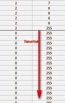
In the first tutorial, I introduced the 433 MHz Transmitter and Receiver with a simple sketch to test their functionality. In the second tutorial, the 433MHz receiver was used to receive a signal from an RF remote. The RF remote signal was coded based on the pattern and length of its HIGH and LOW signals. The signals received by the remote can be described by the code below:

 
Code comparison table


The RF remote that I am using transmits the same signal 6 times in a row. The signal to turn the light on is different from that used to turn the light off. In tutorial 2, we were able to "listen to" or receive the signal from the RF remote using the RF receiver. I thought it would be possible to just play back the signal received on the Arduino's analogPin, but the time it takes to perform a digital write is different to the time it takes to do an AnalogRead. Therefore it won't work. You need to slow down the digitalWrite speed.
I would like to find out if it is possible to apply this delay to all 433 MHz signal projects, however, I only have one 433 MHz remote.

If the delay in your project is the same as mine (or different) I would be keen to know - please leave a comment at the end of the tutorial.

We are going to use trial and error to find the optimal digitalWrite delay time. We will do this by slowly incrementing the delay until the transmission is successful. The transmission is considered successful if the fan-light turns on/off. All we have to do is count the number of transmissions until it is successful, then we should be able to calculate the delay.


Parts Required


The Transmitter Fritzing Sketch


RF Calibration - Arduino Sketch


I used an array to hold the RF code for light ON and light OFF. Each number within the code represents a specific sequence of HIGH and LOW lengths. For example, 2 represents a SHORT HIGH and a LONG LOW combination. A short length = 3, a long length = 7, and a very long length = 92. You need to multiply this by the timeDelay variable to identify how much time to transmit the HIGH and LOW signals for.
The short and long lengths were identified from the experiments performed in tutorial 2 (using the RF receiver). Each code is transmitted 6 times. The LED is turned on at the beginning of each transmission, and then turned off at the end of the transmission. The timeDelay variable starts at 5 microseconds, and is incremented by 10 microseconds with every transmission.
In the video, you will notice that there is some flexibility in the timeDelay value. The Mercator Fan/Light will turn on and off when the timeDelay variable is anywhere between 75 and 135 microseconds in length. It also seems to transmit successfully when the timeDelay variable is 175 microseconds.
So in theory, if we want to transmit a signal to the fan/light, we should be able to use any value between 75 and 135, however in future projects, I think I will use a value of 105, which is right about the middle of the range.


Video


  Now that I have the timeDelay variable, I should be able to simplify the steps required to replicate a remote control RF signal. Maybe there is room for one more tutorial on this topic :)

Update: Here it is - tutorial 4
Where you can record and playback an RF signal (without using your computer).


433 MHz RF module with Arduino Tutorial 2


There are 4 parts to this tutorial:
To get the most out of this tutorial - it is best to start at tutorial Part 1, and then progress to Part 2 then Part 3 and then do Part 4 last. Doing the RF tutorials in this order will help you to understand the process better.


Project 2: RF Remote Copy

In the previous project, we transmitted a signal wirelessly from one Arduino to another. It was there to help troubleshoot communication between the modules. It was important to start with a very short distance (1-2 cm) and then move the RF modules further apart to test the range. The range can be extended by soldering an antenna to the module, or by experimenting with different voltage supplies to the modules (making sure to keep within the voltage limits of the modules.)
In this project - we aim to receive a signal from an RF remote. The remote that I am using is a Mercator Remote Controller for a Fan/Light. (Remote controller code is FRM94). It is important that you use a remote that transmits at the same frequency as your receiver. In this case, my remote just happens to use a frequency of 433MHz. I was able to receive RF signals from from a distance of about 30cm without an antenna (from my remote to the receiver).


Video


Here are the parts that you will need to carry out this project:
 

Parts Required


Remote Controller


You can quickly test your remote, by pressing one of the buttons in close proximity to the RF receiver (using the same sketch as in Project 1), and you should see the LED flicker on an off in response to the button press. If you don't see the LED flickering, then this project will not work for you.

Here is a picture of the remote controller that I am using:


Arduino Sketch - Remote Receiver

The following sketch will make the Arduino wait until a signal is detected from the remote (or other 433 MHz RF device). Once triggered, it will turn the LED ON, and start to collect and store the signal data into an array.
I did my best to keep the signal reading section of the sketch free from other functions or interruptions.The aim is to get the Arduino to focus on reading ONLY... and once the reading phase is complete, it will report the signal data to the Serial monitor. So you will need to have the Serial monitor open when you press the remote control button.
The remote control signal will be made up of HIGH and LOW signals - which I will try to illustrate later in the tutorial. But for now, all you need to know is that the Signal will alternate between HIGH and LOW signals, and that they can be different lengths.
This sketch aims to identify how long each LOW and HIGH signal is (to make up the complete RF remote signal). I have chosen to capture 500 data points(or 250 LOW/HIGH combinations).You may wish to increase or decrease the dataSize variable to accomodate your specific RF signal. In my case, I only really needed 300 data points, because there was a "flat" signal for the last 200 data points (characterised by 200 repetitions of a LOW signal length of 0 and HIGH signal length of 255)

--------------------------------------------------


Receiver Fritzing Sketch


Results

After pressing the button on the RF remote, the data signal is printed to the Serial Monitor. You can copy the data to a spreadsheet program for review. This is an example of the signal produced after pushing the button on the remote for turning the fan/light on.
The following code was produced from pushing the button responsible for turning the light off:
The code sequence above may seem a bit random until you start graphing it. I grabbed the LOW column - and produced the following chart:
The chart above is a bit messy - mainly because the timing is slightly out... in that sometimes it can squeeze an extra read from a particular signal. But what is important to note here is that you can differentiate a LONG signal from a SHORT signal. I have drawn a couple of red dotted lines where I believe most of the readings tend to sit. I then used a formula in the spreadsheet to calibrate the readings and make them a bit more uniform. For example, if the length of the signal was greater than 4 analogReads, then I converted this to 6. If it was less than 4 analogReads, then I converted it to 2. I used a frequency table to help decide on the cutoff value of 4, and just decided to pick the two values (2 for short, and 6 for long) based on the frequency tables below. I could have chosen 5 as the LONG value, but there were more 6's overall.

  **The meaning of "frequency" in the following tables relate to the "number of times" a specific signal length is recorded.


And this is the resulting chart:

You will notice that the pattern is quite repetitive. I helped to identify the sections with vertical red lines (near the bottom of the chart). In other words, the signal produced by the remote is repeated 6 times.
I then did the same for the HIGH signal column and combined the two to create the following chart:


You will notice that the HIGH signals also have a repetitive pattern, however have a Very long length at the end of each section. This is almost a break to separate each section.
This is what a single section looks like zoomed in:


SL = [Short LOW] signal. - or short blue bar
SH = [Short HIGH] signal - or short yellow bar
LL = [Long LOW] signal - or long blue bar
LH = [Long HIGH] signal - or long yellow bar
VLH = [Very long HIGH} signal - or very long yellow bar (~92 analogReads in length)


  You will notice that there are only about 6 different combinations of the signals mentioned above. We can use this to create a coding system as described below:


We can use this coding system to describe the signals. The charts below show the difference between turning the LIGHT ON and LIGHT OFF.


PLEASE NOTE: You may notice when you copy the signals from the Serial monitor that you get a series of (0,255) combinations. This is actually a timeout sequence - which generally occurs after the signal is complete.

 Here is an example of what I mean.


This is the end of tutorial 2. In the next tutorial, we will use the code acquired from the remote to turn the FAN LIGHT on and off (using the 433 MHz RF transmitter).

Click here for Tutorial 3

ScottC 26 Jun 18:05

433 MHz RF module with Arduino Tutorial 2

Project 2: RF Remote Copy

In the previous project, we transmitted a signal wirelessly from one Arduino to another. It was there to help troubleshoot communication between the modules. It was important to start with a very short distance (1-2 cm) and then move the RF modules further apart to test the range. The range can be extended by soldering an antenna to the module, or by experimenting with different voltage supplies to the modules (making sure to keep within the voltage limits of the modules.)

In this project - we aim to receive a signal from an RF remote. The remote that I am using is a Mercator Remote Controller for a Fan/Light. (Remote controller code is FRM94). It is important that you use a remote that transmits at the same frequency as your receiver. In this case, my remote just happens to use a frequency of 433MHz. I was able to receive RF signals from from a distance of about 30cm without an antenna (from my remote to the receiver).


Video


Here are the parts that you will need to carry out this project:
 

Parts Required


Remote Controller

You can quickly test your remote, by pressing one of the buttons in close proximity to the RF receiver (using the same sketch as in Project 1), and you should see the LED flicker on an off in response to the button press. If you don't see the LED flickering, then this project will not work for you.

Here is a picture of the remote controller that I am using:


Arduino Sketch - Remote Receiver

The following sketch will make the Arduino wait until a signal is detected from the remote (or other 433 MHz RF device). Once triggered, it will turn the LED ON, and start to collect and store the signal data into an array.

I did my best to keep the signal reading section of the sketch free from other functions or interruptions.The aim is to get the Arduino to focus on reading ONLY... and once the reading phase is complete, it will report the signal data to the Serial monitor. So you will need to have the Serial monitor open when you press the remote control button.

The remote control signal will be made up of HIGH and LOW signals - which I will try to illustrate later in the tutorial. But for now, all you need to know is that the Signal will alternate between HIGH and LOW signals, and that they can be different lengths.

This sketch aims to identify how long each LOW and HIGH signal is (to make up the complete RF remote signal). I have chosen to capture 500 data points(or 250 LOW/HIGH combinations).You may wish to increase or decrease the dataSize variable to accomodate your specific RF signal. In my case, I only really needed 300 data points, because there was a "flat" signal for the last 200 data points (characterised by 200 repetitions of a LOW signal length of 0 and HIGH signal length of 255)


--------------------------------------------------
 1
2
3
4
5
6
7
8
9
10
11
12
13
14
15
16
17
18
19
20
21
22
23
24
25
26
27
28
29
30
31
32
33
34
35
36
37
38
39
40
41
42
43
44
45
46
47
48
49
50
51
52
53
54
55
56
57
58
59
60
61
62
63
64
65
66
67
68
69
70
71
72
73
74
75
76
77
78
79
80
81
82
83
84
85
86
87


/* 
  RF Remote Capture sketch 
     Written by ScottC 24 Jun 2014
     Arduino IDE version 1.0.5
     Website: http://arduinobasics.blogspot.com
     Receiver: XY-MK-5V
     Description: Use Arduino to Receive RF Remote signal          
 ------------------------------------------------------------- */

 const int dataSize = 500; //Arduino memory is limited (max=1700)
 byte storedData[dataSize]; //Create an array to store the data
 #define ledPin 13           //Onboard LED = digital pin 13
 #define rfReceivePin A0     //RF Receiver data pin = Analog pin 0
 const unsigned int upperThreshold = 100; //upper threshold value
 const unsigned int lowerThreshold = 80; //lower threshold value
 int maxSignalLength = 255; //Set the maximum length of the signal
 int dataCounter = 0; //Variable to measure the length of the signal
 unsigned long startTime=0; //Variable to record the start time
 unsigned long endTime=0; //Variable to record the end time
 unsigned long signalDuration=0; //Variable to record signal reading time
 

 void setup(){
  Serial.begin(9600);
  pinMode(ledPin, OUTPUT);
  
  /* The following code will only run ONCE --------------
  ---Press the reset button on the Arduino to run again-- */
  
  while(analogRead(rfReceivePin)<1){
      //Wait here until a LOW signal is received
      startTime=micros(); //Update start time with every cycle.
  }
  digitalWrite(ledPin, HIGH); //Turn LED ON
  
  
  //Read and store the rest of the signal into the storedData array
  for(int i=0; i<dataSize; i=i+2){
    
    //Identify the length of the LOW signal---------------LOW
    dataCounter=0; //reset the counter
    while(analogRead(rfReceivePin)>upperThreshold && dataCounter<maxSignalLength){
      dataCounter++;
    }
    storedData[i]=dataCounter;
    
    //Identify the length of the HIGH signal---------------HIGH
    dataCounter=0;//reset the counter
    while(analogRead(rfReceivePin)<lowerThreshold && dataCounter<maxSignalLength){
      dataCounter++;
    }
    storedData[i+1]=dataCounter;
    
    //Any readings between the two threshold values will be ignored.
    //The LOW or HIGH signal length must be less than the variable "maxSignalLength"
    //otherwise it will be truncated. All of the HIGH signals and LOW signals combined
    //must not exceed the variable "dataSize", otherwise it will be truncated.
    //The maximum number of signals is 1700 - if you try to extend this variable to a higher
    //number than 1700 - then the Arduino will freeze up and sketch will not work.
    //-------------------------------------------------------------
  }
  
  endTime=micros(); //Record the end time of the read period.
  signalDuration = endTime-startTime;
  
  digitalWrite(ledPin, LOW);//Turn LED OFF
  
  //Send report to the Serial Monitor
  Serial.println("=====================");
  Serial.print("Read duration: ");
  Serial.print(signalDuration);
  Serial.println(" microseconds");
  Serial.println("=====================");
  Serial.println("LOW,HIGH");
  delay(20);
  for(int i=0; i<dataSize; i=i+2){
    Serial.print(storedData[i]);
    Serial.print(",");
    Serial.println(storedData[i+1]);
    delay(20);
  }
 }

 void loop(){
   //Do nothing here
 }


Receiver Fritzing Sketch

Results

After pressing the button on the RF remote, the data signal is printed to the Serial Monitor. You can copy the data to a spreadsheet program for review. This is an example of the signal produced after pushing the button on the remote for turning the fan/light on.
The following code was produced from pushing the button responsible for turning the light off:
The code sequence above may seem a bit random until you start graphing it. I grabbed the LOW column - and produced the following chart:
 
The chart above is a bit messy - mainly because the timing is slightly out... in that sometimes it can squeeze an extra read from a particular signal. But what is important to note here is that you can differentiate a LONG signal from a SHORT signal. I have drawn a couple of red dotted lines where I believe most of the readings tend to sit. I then used a formula in the spreadsheet to calibrate the readings and make them a bit more uniform. For example, if the length of the signal was greater than 4 analogReads, then I converted this to 6. If it was less than 4 analogReads, then I converted it to 2. I used a frequency table to help decide on the cutoff value of 4, and just decided to pick the two values (2 for short, and 6 for long) based on the frequency tables below. I could have chosen 5 as the LONG value, but there were more 6's overall.
 
  **The meaning of "frequency" in the following tables relate to the "number of times" a specific signal length is recorded.

 
And this is the resulting chart:

You will notice that the pattern is quite repetitive. I helped to identify the sections with vertical red lines (near the bottom of the chart). In other words, the signal produced by the remote is repeated 6 times.
I then did the same for the HIGH signal column and combined the two to create the following chart:


You will notice that the HIGH signals also have a repetitive pattern, however have a Very long length at the end of each section. This is almost a break to separate each section.
This is what a single section looks like zoomed in:


SL = [Short LOW] signal. - or short blue bar
SH = [Short HIGH] signal - or short yellow bar
LL = [Long LOW] signal - or long blue bar
LH = [Long HIGH] signal - or long yellow bar
VLH = [Very long HIGH} signal - or very long yellow bar (~92 analogReads in length)

 
  You will notice that there are only about 6 different combinations of the signals mentioned above. We can use this to create a coding system as described below:


We can use this coding system to describe the signals. The charts below show the difference between turning the LIGHT ON and LIGHT OFF.


PLEASE NOTE: You may notice when you copy the signals from the Serial monitor that you get a series of (0,255) combinations. This is actually a timeout sequence - which generally occurs after the signal is complete.
 
 Here is an example of what I mean.


This is the end of tutorial 2. In the next tutorial, we will use the code acquired from the remote to turn the FAN LIGHT on and off (using the 433 MHz RF transmitter).

Click here for Tutorial 3

ScottC 26 Jun 18:05

433 MHz RF module with Arduino Tutorial 1


There are 4 parts to this tutorial:
To get the most out of this tutorial - it is best to start at tutorial Part 1, and then progress to Part 2 then Part 3 and then do Part 4 last. Doing the RF tutorials in this order will help you to understand the process better.


If you are looking for a way to communicate between Arduinos, but don't have much cash at your disposal, then look no further. These RF modules are not only affordable, but easy to use. They are much easier to set up than an XBee, plus you can use them without the need of a special shield. Before you rush out and buy a ton of these modules, make sure that you are not breaking any radio transmission laws in your country. Do your research, and buy them only if you are allowed to use them in your area. There are a few [OPTIONAL] libraries that can be used to help you and your particular project.


I will mention at this point however, that I did NOT use any libraries in this particular tutorial. That's right. I will show how easy it is to transmit data from one arduino to another using these RF modules WITHOUT libraries.

Also if you are looking for an easy way to record the signals and play them back without a computer - then jump to this tutorial.

Video


Project 1- RF Blink


Firstly we need to test if the RF modules are working. So we will design a very simple transmit and receive sketch to test their functionality. We will use the Arduino's onboard LED to show when the transmitter is transmitting, and when the other Arduino is receiving. There will be a slight delay between the two Arduinos. You can solder an antenna onto these modules, however I did not do this, I just kept the modules close together (1-2cm apart). I also found that I was getting better accuracy when I used 3V instead of 5V to power the receiver. While using 5V for VCC on the receiver, I would get a lot of interference, however with 3V, I hardly got any noise. If you find you are getting unpredictable results, I would suggest you switch to 3V on the receiver and move the transmitter and receiver modules right next to each other. Remember this is just a check... you can experiment with an antenna or a greater distance afterwards.

Here are the parts that you will need to carry out this project:
 

Parts Required


The Transmitter and Receiver Fritzing Sketch


The Transmitter

The transmitter has 3 pins


 Notice the pin called "ATAD". It took me a while to figure out what ATAD stood for, when I suddenly realised that this was just a word reversed. It should be DATA (not ATAD). Nevertheless, this is the pin responsible for transmitting the signal. We will make the Arduino's onboard LED illuminate when the transmitter pin is HIGH, and go off when LOW as described in the following table.


And this is the Arduino Sketch to carry out the data transmission.


Arduino sketch - Transmitter


The Receiver


If all goes to plan, the onboard LED on this Arduino should light up (and go off) at the same time as the onboard LED on the transmitting Arduino. There is a chance that the receiver may pick up stray signals from other transmitting devices using that specific frequency. So you may need to play around with the threshold value to eliminate the "noise". But don't make it too big, or you will eliminate the signal in this experiment. You will also notice a small delay between the two Arduinos.


Arduino sketch - Receiver


When a HIGH signal is transmitted to the other Arduino. It will produce an AnalogRead = 0.
When a LOW signal is transmitted, it will produce an AnalogRead = 400.
This may vary depending on on your module, and voltage used.
The signals received can be viewed using the Serial Monitor, and can be copied into a spreadsheet to create a chart like this:


You will notice that the HIGH signal (H) is constant, whereas the LOW signal (L) is getting smaller with each cycle. I am not sure why the HIGH signal produces a Analog reading of "0". I would have thought it would have been the other way around. But you can see from the results that a HIGH signal produces a 0 result and a LOW signal produces a value of 400 (roughly).


Tutorial 2

In tutorial 2, we will receive and display a signal from a Mercator RF Remote Controller for Fan/Light.


Tutorial 3

In tutorial 3 - we use the signal acquired from tutorial 2, and transmit the signal to the fan/light to turn the light on and off.


Tutorial 4

In tutorial 4 - we use the information gathered in the first 3 tutorials and do away with the need for a computer. We will listen for a signal, store the signal, and then play it back by pressing a button. Similar to a universal remote ! No libraries, no sound cards, no computer. Just record signal and play it back. Awesome !!


If you like this page, please do me a favour and show your appreciation :

  Visit my ArduinoBasics Google + page.
Follow me on Twitter by looking for ScottC @ArduinoBasics.
Have a look at my videos on my YouTube channel.


However, if you do not have a google profile...
Feel free to share this page with your friends in any way you see fit.


© Copyright by ScottC

433 MHz RF module with Arduino Tutorial 1


If you are looking for a way to communicate between Arduinos, but don't have much cash at your disposal, then look no further. These RF modules are not only affordable, but easy to use. They are much easier to set up than an XBee, plus you can use them without the need of a special shield. Before you rush out and buy a ton of these modules, make sure that you are not breaking any radio transmission laws in your country. Do your research, and buy them only if you are allowed to use them in your area. There are a few [OPTIONAL] libraries that can be used to help you and your particular project.


I will mention at this point however, that I did NOT use any libraries in this particular tutorial. That's right. I will show how easy it is to transmit data from one arduino to another using these RF modules WITHOUT libraries.

Also if you are looking for an easy way to record the signals and play them back without a computer - then jump to this tutorial.

Video


Project 1- RF Blink


Firstly we need to test if the RF modules are working. So we will design a very simple transmit and receive sketch to test their functionality. We will use the Arduino's onboard LED to show when the transmitter is transmitting, and when the other Arduino is receiving. There will be a slight delay between the two Arduinos. You can solder an antenna onto these modules, however I did not do this, I just kept the modules close together (1-2cm apart). I also found that I was getting better accuracy when I used 3V instead of 5V to power the receiver. While using 5V for VCC on the receiver, I would get a lot of interference, however with 3V, I hardly got any noise. If you find you are getting unpredictable results, I would suggest you switch to 3V on the receiver and move the transmitter and receiver modules right next to each other. Remember this is just a check... you can experiment with an antenna or a greater distance afterwards.

Here are the parts that you will need to carry out this project:
 

Parts Required


The Transmitter and Receiver Fritzing Sketch


The Transmitter

The transmitter has 3 pins,
Notice the pin called "ATAD". It took me a while to figure out what ATAD stood for, when I suddenly realised that this was just a word reversed. It should be DATA (not ATAD). Nevertheless, this is the pin responsible for transmitting the signal. We will make the Arduino's onboard LED illuminate when the transmitter pin is HIGH, and go off when LOW as described in the following table.


And this is the Arduino Sketch to carry out the data transmission.

Arduino sketch - Transmitter

1
2
3
4
5
6
7
8
9
10
11
12
13
14
15
16
17
18
19
20
21
22
23
24
25
26
27
28
29
 /* 
RF Blink - Transmit sketch 
    Written by ScottC 17 Jun 2014
    Arduino IDE version 1.0.5
    Website: http://arduinobasics.blogspot.com
    Transmitter: FS1000A/XY-FST
    Description: A simple sketch used to test RF transmission.          
------------------------------------------------------------- */

#define rfTransmitPin 4  //RF Transmitter pin = digital pin 4
#define ledPin 13        //Onboard LED = digital pin 13

void setup(){
  pinMode(rfTransmitPin, OUTPUT);
  pinMode(ledPin, OUTPUT);
}

void loop(){
  for(int i=4000; i>5; i=i-(i/3)){
    digitalWrite(rfTransmitPin, HIGH); //Transmit a HIGH signal
    digitalWrite(ledPin, HIGH); //Turn the LED on
    delay(2000); //Wait for 1 second
    
    digitalWrite(rfTransmitPin,LOW); //Transmit a LOW signal
    digitalWrite(ledPin, LOW); //Turn the LED off
    delay(i); //Variable delay
  }
}


The Receiver


If all goes to plan, the onboard LED on this Arduino should light up (and go off) at the same time as the onboard LED on the transmitting Arduino. There is a chance that the receiver may pick up stray signals from other transmitting devices using that specific frequency. So you may need to play around with the threshold value to eliminate the "noise". But don't make it too big, or you will eliminate the signal in this experiment. You will also notice a small delay between the two Arduinos.


Arduino sketch - Receiver

1
2
3
4
5
6
7
8
9
10
11
12
13
14
15
16
17
18
19
20
21
22
23
24
25
26
27
28
29
30
31
32
33
34
 /* 
 RF Blink - Receiver sketch 
    Written by ScottC 17 Jun 2014
    Arduino IDE version 1.0.5
    Website: http://arduinobasics.blogspot.com
    Receiver: XY-MK-5V
    Description: A simple sketch used to test RF transmission/receiver.          
------------------------------------------------------------- */

#define rfReceivePin A0  //RF Receiver pin = Analog pin 0
#define ledPin 13        //Onboard LED = digital pin 13

unsigned int data = 0; // variable used to store received data
const unsigned int upperThreshold = 70; //upper threshold value
const unsigned int lowerThreshold = 50; //lower threshold value

void setup(){
  pinMode(ledPin, OUTPUT);
  Serial.begin(9600);
}

void loop(){
  data=analogRead(rfReceivePin); //listen for data on Analog pin 0
  
  if(data>upperThreshold){
    digitalWrite(ledPin, LOW); //If a LOW signal is received, turn LED OFF
    Serial.println(data);
  }
  
  if(data<lowerThreshold){
    digitalWrite(ledPin, HIGH); //If a HIGH signal is received, turn LED ON
    Serial.println(data);
  }
}


When a HIGH signal is transmitted to the other Arduino. It will produce an AnalogRead = 0.
When a LOW signal is transmitted, it will produce an AnalogRead = 400.
This may vary depending on on your module, and voltage used.
The signals received can be viewed using the Serial Monitor, and can be copied into a spreadsheet to create a chart like this:


You will notice that the HIGH signal (H) is constant, whereas the LOW signal (L) is getting smaller with each cycle. I am not sure why the HIGH signal produces a Analog reading of "0". I would have thought it would have been the other way around. But you can see from the results that a HIGH signal produces a 0 result and a LOW signal produces a value of 400 (roughly).


Tutorial 2

In tutorial 2, we will receive and display a signal from a Mercator RF Remote Controller for Fan/Light.


Tutorial 3

In tutorial 3 - we use the signal acquired from tutorial 2, and transmit the signal to the fan/light to turn the light on and off.


Tutorial 4

In tutorial 4 - we use the information gathered in the first 3 tutorials and do away with the need for a computer. We will listen for a signal, store the signal, and then play it back by pressing a button. Similar to a universal remote ! No libraries, no sound cards, no computer. Just record signal and play it back. Awesome !!


If you like this page, please do me a favour and show your appreciation :

  Visit my ArduinoBasics Google + page.
Follow me on Twitter by looking for ScottC @ArduinoBasics.
Have a look at my videos on my YouTube channel.


However, if you do not have a google profile...
Feel free to share this page with your friends in any way you see fit.

© Copyright by ScottC

LayerOne badges stop bullets; drive away

We love badges. And we’ve really got to thank [Charliex] for taking the time to write a huge post about this year’s LayerOne badges, especially since they’ve got their backs up against the deadline for pulling everything together in time.

Here it is, the stock badge on the left, with an add-on shield on the right. Now the original intent was to make this badge the chassis of an RC car. [Charliex] chewed through his development time trying to source toy cars that could be gutted for parts that would mount easily on the badge. This looked promising at first, but turned out to be folly. Instead what we have here is an Arduino compatible board with an RF transmitter which can be cut off and used separately if you wish. Attendees will be able to use the badge to take control of the toy cars (cases of them have been shipped to the conference), with the option to use the USB functionality to facilitate automation.

So what about stopping bullets? There is a bug in the module [Charliex] used to export the board design from Eagle. They came back from the fab house as 0.125″ substrate. That’s pretty beefy!

The conference is this weekend… better get on that!


Filed under: cons
Hack a Day 24 May 19:01
arduino  badge  badges  cons  layerone  rc  remote control  rf  shield