Posts with «neopixel» label

Electronic Connect 4 Console Doesn’t Use LCD
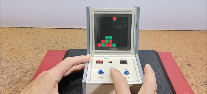
You might think that making your own electronic games would require some kind of LCD, but lately, [Mirko Pavleski] has been making his using inexpensive 8X8 WS2812B LED panels. This lets even a modest microcontroller easily control a 64-pixel “screen.” In this case, [Mirko] uses an Arduino Nano, 3 switches, and a buzzer along with some 3D printed components to make a good-looking game. You can see it in action in the video below.

The WS2812B panels are easy to use since the devices have a simple protocol where you only talk to the first LED. You send pulses to determine each LED’s color. The first LED changes color and then starts repeating what you send to the next LED, which, of course, does the same thing. When you pause a bit, the array decides you are done, and the next train of pulses will start back at the first LED.

It looks like the project is based on a German project from [Bernd Albrecht], but our German isn’t up to snuff, and machine translation always leaves something to be desired. Another developer added a play against the computer mode. This is a simple program and would be easy to port to the microcontroller of your choice. [Mirko]’s execution of it looks like it could be a commercial product. If you made one as a gift, we bet no one would guess you built it yourself.

Of course, you could play a real robot. You could probably repurpose this hardware for many different games, too.

Hack a Day 29 May 03:00

The Great Resistor Embiggens the Smallest Value

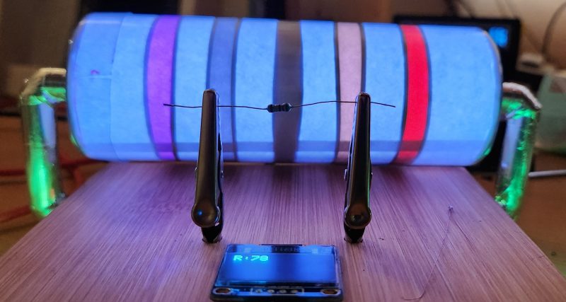
With surface-mount components quickly becoming the norm, even for homebrew hardware, the resistor color-code can sometimes feel a bit old-hat. However, anybody who has ever tried to identify a random through-hole resistor from a pile of assorted values will know that it’s still a handy skill to have up your sleeve. With this in mind, [j] decided to super-size the color-code with “The Great Resistor”.

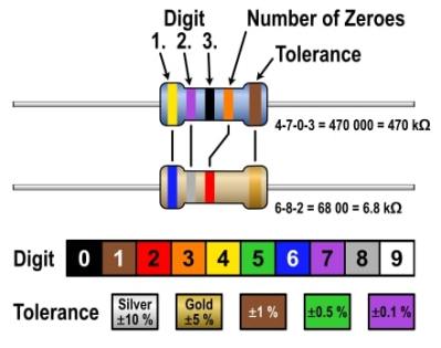
How the resistor color-code bands work

At the heart of the project is an Arduino Nano clone and a potential divider that measures the resistance of the test resistor against a known fixed value. Using the 16-bit ADC, the range of measurable values is theoretically 0 Ω to 15 MΩ, but there are some remaining issues with electrical noise that currently limit the practical range to between 100 Ω and 2 MΩ.

[j] is measuring the supply voltage to help counteract the noise, but intends to move to an oversampling/averaging method to improve the results in the next iteration.

The measured value is shown on the OLED display at the front, and in resistor color-code on an enormous symbolic resistor lit by WS2812 RGB LEDs behind.

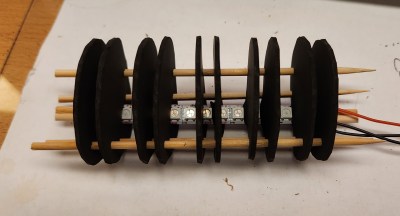
Inside The Great Resistor, the LEDs and baffle plates make the magic work

Precision aside, the project looks very impressive and we like the way the giant resistor has been constructed. It would look great at a science show or a demonstration. We’re sure that the noise issues can be ironed out, and we’d encourage any readers with experience in this area to offer [j] some tips in the comments below. There’s a video after the break of The Great Resistor being put through its paces!

If you want to know more about the history of the resistor color code bands, then we have you covered.  Alternatively, how about reading the color code directly with computer vision?

Speed up CircuitPython LED animations 10x!

In many LED animations, you need to apply an operation to all LEDs as fast as possible. Often this is “fadeToBlackBy”, i.e. “dim all LEDs by some amount”. There are some common effects that you can easily get back using that and one other action. For example: the Cylon effect is “Turn an LED on, [...]

Building a Tessellated NeoPixel Clock

Anyone can buy a clock, but building your own lets you express your creative flair along the way. [Edison Science Corner] did just that with this neat sci-fi looking design.

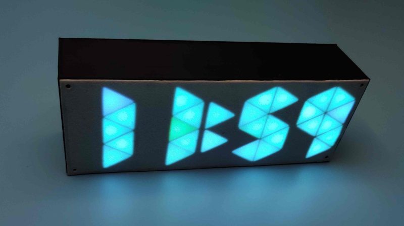
The build relies on an Arduino Pro Mini to run the show, paired with a DS3231 real-time clock module. The latter part is of great importance, as without it, the Arduino would not keep accurate time. The 3D printed enclosure looks nondescript from the outside. However, inside, it’s got a neat triangular structure which allows the time to be displayed in that attractive tessellated triangular fashion. There’s a black plastic separator between all the segments which stop unattractive bleed-through and really help with the final effect. The individual triangles are each lit by a NeoPixel LED, which are both addressable and capable of lighting up in RGB colors. It makes for an attractive and colorful display.

If you want to try something more traditional yet challenging, consider whipping up your own 7-segment displays. Video after the break.

Hack a Day 02 Oct 00:00

Jigsaw Puzzle Lights Up With Each Piece

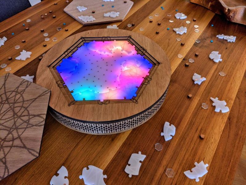
Putting the last piece of a project together and finally finishing it up is a satisfying feeling. When the last piece of a puzzle like that is a literal puzzle, though, it’s even better. [Nadieh] has been working on this jigsaw puzzle that displays a fireworks-like effect whenever a piece is placed correctly, using a lot of familiar electronics and some unique, well-polished design.

The puzzle is a hexagonal shape and based on a hexagonally symmetric spirograph, with the puzzle board placed into an enclosure which houses all of the electronics. Each puzzle piece has a piece of copper embedded in a unique location so when it is placed on the board, the device can tell if it was placed properly or not. If it was, an array of color LEDs mounted beneath a translucent diffuser creates a lighting effect that branches across the entire board like an explosion. The large number of pieces requires a multiplexer for the microcontroller, an ATtiny3216.

This project came out of a FabAcademy, so the documentation is incredibly thorough. In fact, everything on this project is open sourced and available on the project page from the code to the files required for cutting out the puzzle pieces and the enclosure. It’s an impressive build with a polish we would expect from a commercial product, and reminds us of an electrified jigsaw puzzle we saw in a previous build.

Thanks to [henk] for the tip!

QTPy-knob: Simple USB knob w/ CircuitPython

I like minimal solutions to problems. I was playing with a CircuitPython-enabled QT Py on a breadboard with and a rotary encoder and I ended up making a USB knob, like many others have done before. But I realized: waitaminute, I can literally just plug the encoder directly onto the QT Py… Thus was born [...]
Todbot 26 Feb 01:10
hardware-hacking  hid  knob  neopixel  qtpy  usb  

DIY Neopixel / WS2812 Development Kit

If you are like me, you play around with Neopixel / WS2812-style LEDs a lot. Normally I solder my own custom-connectors and don’t use the ones that come with the reels I buy. But since we’ve been playing around with WS2812-compatible Xmas lights, I decided to make a “Neopixel Dev Kit” for easier experimenting with [...]
Todbot 08 Jan 21:09

WS2812-compatible “fairy light” LEDs that know their address

I’ve not done much on our plotter Xmas tree this week because, well… if you follow me on Twitter, it’s likely you’ve seen me ramble on about these crazy new Christmas Tree lights we got for our tree (first tree ever!). They appeared to maybe be WS2812 / Neopixel compatible and yup, they were! But [...]
Todbot 01 Jan 21:49

Dad Scores Big with DIY Indoor Hockey Game

We suppose it’s a bit early to call it just yet, but we definitely have a solid contender for Father of the Year. [DIY_Maxwell] made a light-up hockey game for his young son that looks like fun for all ages. Whenever the puck is hit with the accompanying DIY hockey stick (or anything else), it lights up and produces different sounds based on its acceleration.

Inside the printed puck is an Arduino Nano running an MPU6050 accelerometer, a 12-NeoPixel ring, and a piezo buzzer. [DIY_Maxell] reused a power bank charging circuit to charge up the small LiPo battery.

The original circuit used a pair of coin cells, but the Arduino was randomly freezing up, probably because of the LEDs’ current draw. Be sure to check out the video after the break, which begins with a little stop motion and features a solder stand in the shape of a 3D printer.

Got a house full of carpet or breakables? You could always build an air hockey table instead.

Greeking out with Arduinos

Learning a new language is hard work, but they say that the best way to learn something is to teach it. [Angeliki Beyko] is learning Greek, and what better way to teach than to build a vocabulary flash-card game from Arduinos, color screens, 1602 text screens, and arcade buttons? After the break, we have a video from the creator talking about how to play, the hardware she chose, and what to expect in the next version.

Pegboard holds most of the hardware except the color screens, which are finicky when it comes to their power source. The project is like someone raided our collective junk drawers and picked out the coolest bits to make a game. Around the perimeter are over one hundred NeoPixels to display the game progress and draw people like a midway game. Once invested, you select a category on the four colored arcade buttons by looking at the adjacent LCD screens’ titles. An onboard MP3 shield reads a pseudo-random Greek word and displays it on the top-right 1602 screen in English phonetics. After that, it is multiple choice with your options displaying in full-color on four TFT monitors. A correct choice awards you a point and moves to the next word, but any excuse to mash on arcade buttons is good enough for us.

[Angeliki] does something we see more often than before, she’s covering what she learned, struggled with, would do differently, and how she wants to improve. We think this is a vital sign that the hacker community is showcasing what we already knew; hackers love to share their knowledge and improve themselves.

Typing Greek with a modern keyboard will have you reaching for an alt-code table unless you make a shortcut keyboard, and if you learn Greek, maybe you can figure out what armor they wore to battle.