Today’s class went much better than last Friday’s.
I took the advice one of the students gave me last we and started with a “do now” question. (She had actually suggested an “exit ticket”, but I don’t have the time management skills to leave a block of time at the end of class.) The question I asked was a design task that was easy if you knew what you were doing, but subtly harder than the standard sort of text-book question, because it was a design question, not an analysis question:
You have sensor whose resistance varies from 1kΩ to 4kΩ with the property it measures. Design a circuit whose output voltage varies from 1v (at 1kΩ) to 2v (at 4kΩ).
I gave the students 10 minutes to work on this at the beginning of class. A good question to prompt discussion (according to the peer instruction blogs and websites) should be answerable by 30–80% of the students. More than that and the question was too easy to be useful, and less than that and the question is too hard for peer discussion to be worthwhile. It turned out that no one had gotten it after 10 minutes (too hard to use as a peer instruction question), so we used it as the basis for a class discussion.
Almost everyone realized that the desired circuit was a voltage source and a voltage divider (not too surprising, since that’s the only circuit they’ve used so far). The majority also realized that the variable resistor had to be on the lower leg, between the output and ground, and a couple of the students could articulate why. I suggested the common heuristic of trying extreme values (0 and ∞) for the variable resistor, to see whether the output voltage would go up or down as the resistance changed.
The students were then able to set up the simultaneous equations to solve for the input voltage and the fixed resistance. The hole in everyone’s thinking when working on the problem initially is that they had not considered the voltage of the source as a design parameter to solve for, though one student had asked about it. This was the blind spot I was expecting, so I was able to use it as a teachable moment. After we had the equations set up using mainly student input, I gave the students another minute or two to solve them, and about half the class was able to solve them correctly in the time provided. (I suspect that everyone could have if given enough time, but I didn’t want to take any more time in class—those who didn’t solve it in class could practice their algebra at home if they needed to.) One student had made an algebra or arithmetic mistake, and gotten a source voltage smaller than one of the desired output voltages. This was also a good mistake to get, since we could use it to talk about sanity checks on results.
I think that the 20 or so minutes of class was well spent, as we uncovered several important misconceptions, and raised awareness of all unspecified variables as potential design parameters, reasoning using extreme values, and the usefulness of sanity checks.
After that, we spent some time discussing different temperature sensors. From the students, I got thermistor, infrared thermometer, mercury thermometer+camera, and enzyme + other sensor (pH, conductivity, color, …). I added RTD, silicon band-gap, and thermocouple to the mix. We talked a little about the advantages and disadvantages of each. At the end, I also threw in bimetallic strips and tilt switches for one-bit digitization of temperature. I wonder how many students will look at the thermostats in their apartments and try to figure out what sensor they include.
For the remainder of the class, we talked about gnuplot commands, particularly the “plot” command.
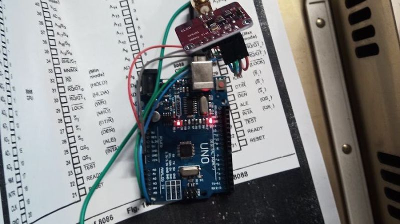
After class, several of us went over to the lab, where my son met us and helped the students install the DataLoger, python, pyserial, the Arduino environment, and gnuplot. While he was doing that, I borrowed an Uno R3 Arduino board and made sure that all the computers in the labs had the drivers installed for it. We had 2 installation failures: on one Windows laptop, my son was unable to get the serial ports to work and one Mac laptop couldn’t install gnuplot.
The problem with the gnuplot installation on that Mac was not solvable by the techniques in the comments for Installing gnuplot—a nightmare, because all the methods there assume that you can install the command-line tools “make” and “gcc”. The Mac had 10.6.8 installed, but the student had never bothered to install the development tools and had lost the original CD-ROM with the Xcode tools on it. The Apple Developer site does not provide the command-line tools for anything older than 10.7.3. The only workaround we could find was to download the 4.1GByte complete Xcode suite for OS 10.6.8, which I was not willing to wait around for. (Other students with 10.6.8 had no trouble installing gnuplot, because they already had the command-line tools, though they’d never used them.)
I did not look at the problem on the Windows machine (the student had to leave for class before I became available), but I don’t know that I could have done anything—my son knows more about Windows than I do, so if he was stuck, I probably would have been also.
Next year I’m going to want to do an install session before the first lab. (Or, if we go to 2 labs a week, as the first lab.)
On Wednesday, I’ll start with another “do now” question, though I’m not sure what it’ll be on, since I’ve not yet gotten to the material for this week’s lab: how a microphone works. I’ll do a tiny bit of gnuplot (just the “fit” command) and try to get through how a microphone works and an idealized i-vs-v plot for the FET output of the microphone.
Filed under:
Circuits course Tagged:
Arduino,
circuits,
gnuplot,
parts,
teaching,
temperature measurement,
voltage divider