Twelve Days of Christmas as Performed By 1980s Speech Chip
In a curious historical twist, the “Twelve days of Christmas” are actually the days of revelry that followed the 25th. The preceding period, Advent, was traditionally a fast, not unlike Lent. When and why a fast became an excuse for chocolate calendars we cannot say, but this historical information is presented to explain that this great hack by [Kevin], making a vintage speech synthesizer chip sing the classic carol will remain relevant at least until January 5th — or perhaps even the 19th, for the Orthodox amongst us.
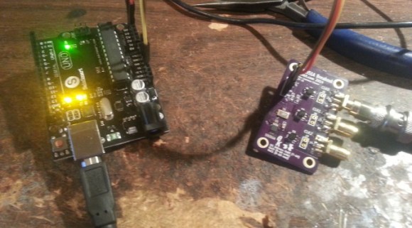
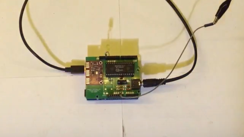
The chip in question is an SP0256A-AL2, which you may remember from various speech projects for 8-bit computers back in the day. It can talk, after a fashion, by reproducing 56 “allophones” — the sounds that make up English speech — from ROM. Singing, though? We cannot recall much of that back in the day, but then, a talking computer was impressive enough.
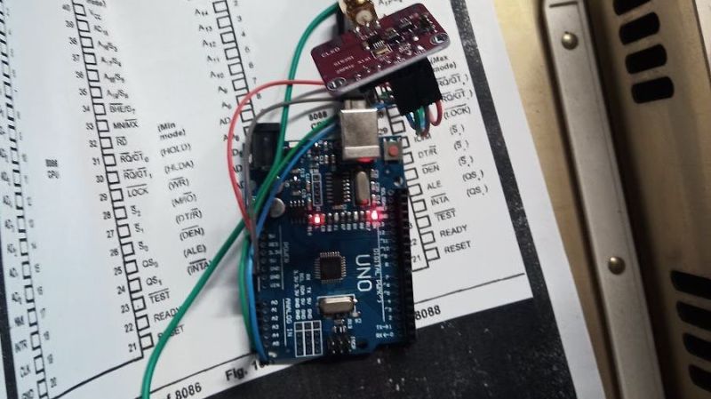
As it turns out this is building on an earlier hack [Kevin] did in which he used an Arduino to make the venerable speech chip MIDI controllable. In that project’s write-up it is revealed that a Si5351 programmable clock module is used to give a variable pitch signal to the speech synthesizer. In this way he’s able to get about an octave an a half, which is good enough when the carol in question only spans one octave.
Of course the pitch signal needs to be varied by something and for that the venerable Arduino once again takes the place of an 8-bit computer. In this case it’s pre-programmed, but can also be set up for MIDI control.Of course nothing says you can’t use true retro hardware or a more-capable RP2040 instead of the Amtel chip.
It’s sad to think how much compute power has been wasted this year on AI-generated novelty carols when a little bit of 1980s silicon and some ingenuity can do nearly as good — or better, depending on your tastes.
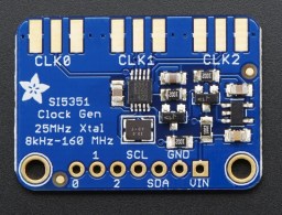 [Tom] used a Teensy 3.1 Arduino compatible board, to control the Si5351