Posts with «cnc hacks» label

The $50 Pen Plotter

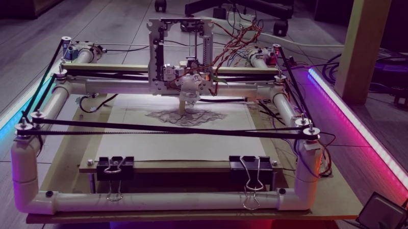
[Arca] sets out to build himself a low-cost pen plotter that doesn’t require access to a 3D printer. The plotter uses a coreXY arrangement, powered by 28BYJ-48 stepper motors, which he overdrives with +12 VDC to increase the torque. Pen up and down control is done using a stepper motor salvaged from a DVD reader. The frame is constructed using PVC electrical conduit and associated fittings, and [Arca] uses the hot glue gun quite liberally. Steppers were driven by A4988 modules with heatsinks, and motion control is provided by GRBL running on an Arduino UNO.

He has a few issues with glitches on the limit switches, and is continuing to tweak the design. There is no documentation yet, but you can discern the construction easily from the video if you want to try your hand at making one of these. This is a really cool DIY plotter, and many parts you probably have laying around your parts boxes. As [Arca] says, it’s not an AxiDraw, but the results are respectable. Keep a lookout for part 2 of this project on his YouTube channel.

Hack a Day 19 Mar 21:00

Simple CNC Gear Production with Arduino

We’ve seen plenty of people 3D printing custom gears over the years, but [Mr Innovative] decided against an additive process for his bespoke component. He ended up using a simple CNC machine that makes use of several components that were either salvaged from a 3D printer or produced on one. Using a small saw blade, the machine cuts gear teeth into some plastic material and — presumably — could cut gears into anything the saw blade was able to slice into, especially if you added a little lubrication, cooling, and dust removal.

If you’ve built a 3D printer, you’ll see a lot of familiar parts. Stepper motors, aluminum extrusion, straight rods, bearing blocks, and rod holders are all used in the build. There’s also a lead screw and the associated components you usually see in a printer’s Z-axis. Naturally, an Arduino drives the whole affair.

The saw blade was custom-made from a washer, grinding an edge and using a 3D printed template to cut teeth in it. We might have been more inclined to use a cut-off wheel from a rotary tool, but this certainly did the trick. An LCD accepts the gear diameter and number of teeth. The stepper rotates the correct number of degrees and another stepper lowers the cutting head which is spinning with a common DC motor.

As impressive as this machine is, the fact remains that a 3D printer can produce more complex designs. For example, a herringbone pattern can help with alignment issues. It has been done many times. You can even use a resin printer, although you might prefer to stick with FDM.

Hack a Day 10 Oct 16:30

Old CNC Brain Swapped With An Arduino

[Sebastian] and [Stefan Shütz] had a ISEL EP1090 CNC machine at home, sitting unused, and they decided to bring it to life. With pretty good mechanical specs, this CNC looked promising – alas, it was severely constrained by its controller. The built-in CPU’s software was severely outdated, had subpar algorithms for motor driving programmed in, and communication with the CNC was limited because the proprietary ISEL communications protocol that isn’t spoken by other devices.The two brothers removed the CPU from its PLCC socket, and went on to wiring a grbl-fueled Arduino into the controller box.

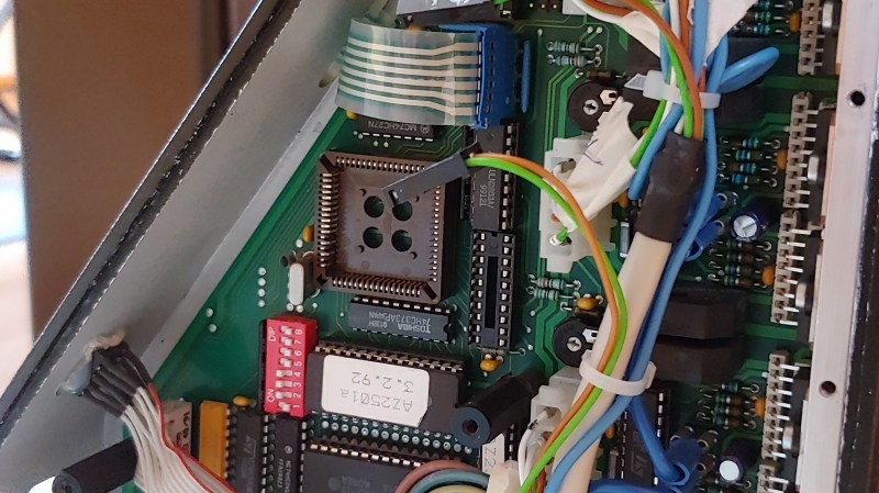
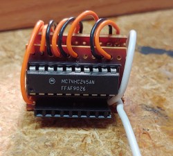
They reverse-engineered the motor driver connections – those go through a 74HC245 buffer between the original CPU and the drivers. Initially, they put an Arduino inside the control box of the CNC and it fit nicely, but it turned out the Arduino’s CPU would restart every time the spindle spun up – apparently, EMC would rear its head. So, they placed the Arduino out of the box, and used two CAT7 cables to wire up the motor and endstop signals to it.

For tapping into these signals, they took the 74HC245 out of its socket, and made an interposer from two small protoboards and some pin headers – letting them connect to the STEP and DIR lines without soldering wires into the original PCB. There’s extensive documentation, GRBL settings, and more pictures in their GitHub repo, too – in case you have a similar CNC and would like to learn about upgrading its controller board!

After this remake, the CNC starts up without hassles. Now, the brothers shall CNC on! Often, making an old CNC machine work is indeed that easy, and old controller retrofits have been a staple of ours. You can indeed use an Arduino, one of the various pre-made controller boards like Gerbil or TinyG, or even a Raspberry Pi – whatever helps you bridge the divide between you and a piece of desktop machinery you ought to start tinkering with.

Minimal Mill: The Minamil

Having a few machine tools at one’s disposal is a luxury that not many of us are afforded, and often an expensive one at that. It is something that a large percentage of us may dream about, though, and with some commonly available tools and inexpensive electronics a few people have put together some very inexpensive CNC machines. The latest is the Minamil, which uses a rotary tool and straps it to an economical frame in order to get a functional CNC mill setup working.

This project boasts impressively low costs at around $15 per axis. Each axis uses readily available parts such as bearings and threaded rods that are readily installed in the mill, and for a cutting head the build is based on a Dremel-like rotary tool that has a similarly low price tag. Let’s not ignore the essentially free counterweight that is used.

For control, an Arduino with a CNC shield powers the three-axis device which is likely the bulk of the cost of this project. [Paul McClay] also points out that a lot of the material he needed for this build can be salvaged from things like old printers, so the $45 price tag is a ceiling, not a floor.

The Minamil has been demonstrated milling a wide variety of materials with excellent precision. Both acrylic and aluminum are able to be worked with this machine, but [Paul] also demonstrates it in its capacity to mill PCBs. It does have some limitations but for the price it seems that this mill can’t be beat, even compared to his previous CNC build which repurposed old CD drives.

The HackadayPrize2021 is Sponsored by:

From Printer to Vinyl Cutter

Some might look at a cheap inkjet printer and see a clunky device that costs more to replace the ink than to buy a new one. [Abhishek Verma] saw an old inkjet printer and instead saw a smooth gantry and feed mechanism, the perfect platform to build his own DIY vinyl cutter.

The printer was carefully disassembled. The feed mechanism was reworked to be driven by a stepper motor with some 3D printed adapter plates. A solenoid-based push/pull mechanism for the cutting blade was added with a 3D printed housing along with a relay module. An Arduino Uno takes in commands from a computer with the help of a CNC GRBL shield.

What we love about this build is the ingenuity and reuse of parts inside the old printer. For example, the old PCB was cut and connectors were re-used. From the outside, it’s hard to believe that HP didn’t manufacture this as a vinyl cutter.

If you don’t have a printer on hand, you can always use your CNC as a vinyl cutter. But if you don’t have a CNC, [Abhishek] shares all the STL files for his cutter as well as the schematic. Video after the break.

Teaching an Old Lathe New Tricks With a Programmable Power Feed

Ask anybody whose spent time standing in front of a mill or lathe and they’ll tell you that some operations can get tedious. When you need to turn down a stainless rod by 1/4″ in 0.030″ increments, you get a lot of time to reflect on why you didn’t just buy the right size stock as you crank the wheel back and forth. That’s where the lead screw comes in — most lathes have a gear-driven lead screw that can be used to actuate the z-axis ( the one which travels parallel to the axis of rotation). It’s no CNC, but this type of gearing makes life easier and it’s been around for a long time.

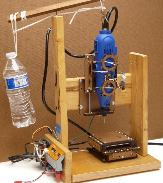
[Tony Goacher] took this idea a few steps further when he created the Leadscrew Buddy. He coupled a beautiful 1949 Myford lathe with an Arduino, a stepper motor, and a handful of buttons to add some really useful capabilities to the antique machine. By decoupling the lead screw from the lathe’s gearbox and actuating it via a stepper motor, he achieved a much more granular variable feed speed.

If that’s not enough, [Tony] used a rotary encoder to display the cutting tool’s position on a home-built Digital Readout (DRO). The pièce de résistance is a “goto” command. Once [Tony] sets a home position, he can command the z-axis to travel to a set point at a given speed. Not only does this make turning easier, but it makes the process more repeatable and yields a smoother finish on the part.

These features may not seem so alien to those used to working with modern CNC lathes, but to the vast majority of us garage machinists, [Tony]’s implementation is an exciting look at how we can step up our turning game. It also fits nicely within the spectrum of lathe projects we’ve seen here at Hackaday- from the ultra low-tech to the ludicrously-precise.

OpenScan 3D Scans All Of The (Small) Things

The OpenScan project has been updated quite a bit since its inception. OpenScan is an open source, Arduino or Raspberry Pi-based 3D scanner for small objects that uses 3D printed hardware and some common electronic components to create 3D scans using photogrammetry; a process by which a series of still images from different angles are used to create a 3D point cloud of an object, which can then be used to generate a 3D model.

Feature visualization overlays detected features onto the camera preview to help judge quality. Broadly speaking, green is good.

Photogrammetry is a somewhat involved process that relies on consistent conditions, so going through the whole process only to find out the results aren’t up to snuff can be tiresome. Happily, OpenScan offers some interesting new functions such as feature visualization via the web interface, which helps a user judge scan quality and make changes to optimize results without having to blindly cross their fingers quite so much. OpenScan remains a one-person project by [Thomas], who is clearly motivated to improve his design and we’re delighted to see it getting updates.

Embedded below is a video that walks through the installation and web interface. It’s a fairly long and comprehensive, but if you like you can skip directly to [Thomas] demonstrating the interface around the 8:22 mark, or watch it below. Interested in your own unit? [Thomas] has an e-shop for parts and the GitHub repository is right here; the project also has its own subreddit.

Photogrammetry isn’t limited to small objects. We have seen some neat applications in the past, where it was the missing link to modeling a custom control panel and making a 3d scan of a custom-molded ergonomic trackball.

A Better Embroidery Machine, With 3D Printing and Common Parts

In concept, an everyday sewing machine could make embroidery a snap: the operator would move the fabric around in any direction they wish while the sewing machine would take care of slapping down stitches of colored thread to create designs and filled areas. In practice though, getting good results in this way is quite a bit more complex. To aid and automate this process, [sausagePaws] has been using CNC to take care of all the necessary motion control. The result is the DIY Embroidery Machine V2 which leverages 3D printed parts and common components such as an Arduino and stepper drivers for an economical DIY solution.

It’s not shown in the photo here, but we particularly like the 3D printed sockets that are screwed into the tabletop. These hold the sewing machine’s “feet”, and allow it to be treated like a modular component that can easily be removed and used normally when needed.

The system consists of a UI running on an Android tablet, communicating over Bluetooth to an Arduino. The Arduino controls the gantry which moves the hoop (a frame that holds a section of fabric taut while it is being embroidered), while the sewing machine lays down the stitches.

[sausagePaws]’s first version worked well, but this new design really takes advantage of 3D printing as well as the increased availability of cheap and effective CNC components. It’s still a work in progress that is a bit light on design details, but you can see it all in action in the video embedded below.

Custom Machined Pump Keeps CNC Lubrication Under Control

Rub two pieces of metal against each other hard enough, and it won’t be long before they heat up sufficiently to cause problems. That’s especially true when one is a workpiece and one is a tool edge, and the problems that arise from failing to manage the heat produced by friction can cost you dearly.

The traditional way of dealing with this is by pumping heavy streams of liquid coolant at the workpiece, but while that works, it creates problems of its own. That’s where minimum quantity lubrication comes in. MQL uses a fine mist of lubricant atomized in a stream of compressed air, which saves on lube and keeps swarf cleaner for easier recycling. The gear needed for MQL can be pricey though, so [brockard] decided to add homebrew MQL to his CNC router, with great results.

The video below shows the whole process, from raw metal to finished system – skip ahead to about 12 minutes if you just want to see final testing, but be warned that you’ll be missing some high-quality machining. The finished pump is a double-piston design, with each side driven by a cam rotated by a servo. An Arduino controls the speed of the motor based on the current settings; the pump is turned on and off through G-code control of a relay.

The lubricant stream is barely visible in the video, as opposed to the sloshing mess of traditional flood coolants, and seems much more suitable for a hobbyist-grade CNC setup. Need to build a CNC router before you build this? You can do much worse than this one.

Thanks for the tip, [Jasper Jans].

Manual 3D Digitizer Works a Bit Like 3-Dimensional Measuring Tape

Digitizing an object usually means firing up a CAD program and keeping the calipers handy, or using a 3D scanner to create a point cloud representing an object’s surfaces. [Dzl] took an entirely different approach with his DIY manual 3D digitizer, a laser-cut and 3D printed assembly that uses rotary encoders to create a turntable with an articulated “probe arm” attached.

Each joint of the arm is also an encoder, and by reading the encoder values and applying a bit of trigonometry, the relative position of the arm’s tip can be known at all times. Manually moving the tip of the arm from point to point on an object therefore creates measurements of that object. [Dzl] successfully created a prototype to test the idea, and the project files are available on GitHub.

We remember the earlier version of this project and it’s great to see how it’s been updated with improvements like the addition of a turntable with an encoder. DIY 3D digitizing takes all kinds of approaches, and one example was this unit that used four Raspberry Pi Zeros and four cameras to generate high quality 3D scans.