Posts with «acrylic» label

Minimal Mill: The Minamil
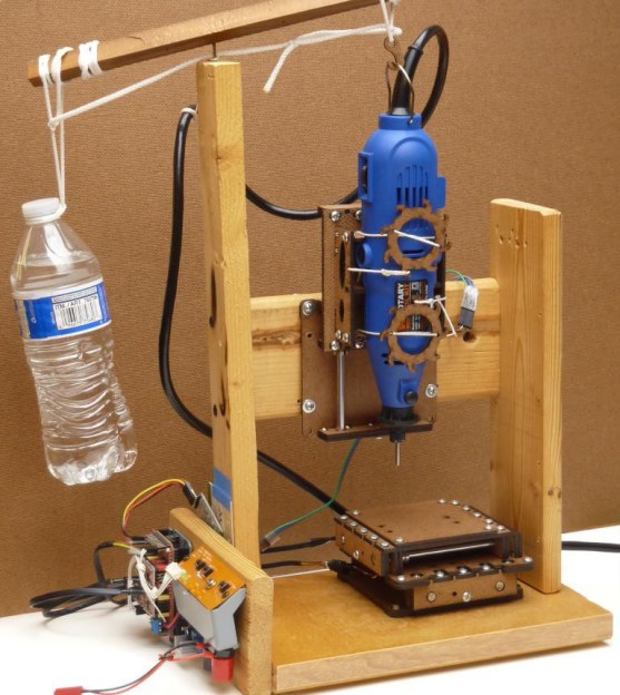
Having a few machine tools at one’s disposal is a luxury that not many of us are afforded, and often an expensive one at that. It is something that a large percentage of us may dream about, though, and with some commonly available tools and inexpensive electronics a few people have put together some very inexpensive CNC machines. The latest is the Minamil, which uses a rotary tool and straps it to an economical frame in order to get a functional CNC mill setup working.

This project boasts impressively low costs at around $15 per axis. Each axis uses readily available parts such as bearings and threaded rods that are readily installed in the mill, and for a cutting head the build is based on a Dremel-like rotary tool that has a similarly low price tag. Let’s not ignore the essentially free counterweight that is used.

For control, an Arduino with a CNC shield powers the three-axis device which is likely the bulk of the cost of this project. [Paul McClay] also points out that a lot of the material he needed for this build can be salvaged from things like old printers, so the $45 price tag is a ceiling, not a floor.

The Minamil has been demonstrated milling a wide variety of materials with excellent precision. Both acrylic and aluminum are able to be worked with this machine, but [Paul] also demonstrates it in its capacity to mill PCBs. It does have some limitations but for the price it seems that this mill can’t be beat, even compared to his previous CNC build which repurposed old CD drives.

The HackadayPrize2021 is Sponsored by:

Lasers, Mirrors, and Sensors Combine in an Optical Bench Game

Who would have thought you could make a game out of an optical bench? [Chris Mitchell] did, and while we were skeptical at first, his laser Light Bender game has some potential. Just watch your eyes.

The premise is simple: direct the beam of a colored laser to the correct target before time runs out. [Chris] used laser-cut acrylic for his playfield, which has nine square cutouts arranged in a grid. Red, green, and blue laser pointers line the bottom of the grid, with photosensors and RGB LEDs lining the grid on the other three sides. Play starts with a random LED lighting up in one of the three colors, acting as a target. The corresponding color laser comes on, and the player has to insert mirrors or pass-through blocks in the grid to create a path to the target. The faster you hit the CdS cell, the higher your score. It’s simple, but it looks really engaging. We can imagine all sorts of upgrades, like lighting up two different targets at once, or adding a beamsplitter block to hit two targets with the same color. Filters and polarizers could add to the optical fun too.

We like builds that are just for fun, especially when they’re well-crafted and have a slight air of danger. The balloon-busting killbots project we featured recently comes to mind.


RGB Disk Goes Interactive with Bluetooth; Shows Impressive Plastic Work

[smash_hand] had a clear goal: a big, featureless, white plastic disk with RGB LEDs concealed around its edge. So what is it? A big ornament that could glow any color or trippy mixture of colors one desires. It’s an object whose sole purpose is to be a frame for soft, glowing light patterns to admire. The disk can be controlled with a simple smartphone app that communicates over Bluetooth, allowing anyone (or in theory anything) to play with the display.

The disk is made from 1/4″ clear plastic, which [smash_hand] describes as plexiglass, but might be acrylic or polycarbonate. [smash_hands] describes some trial and error in the process of cutting the circle; it was saw-cut with some 3-in-1 oil as cutting fluid first, then the final shape cut with a bandsaw.

The saw left the edge very rough, so it was polished with glass polishing compound. This restores the optical properties required for the edge-lighting technique. The back of the disc was sanded then painted white, and the RGB LEDs spaced evenly around the edge, pointing inwards.

The physical build is almost always the difficult part in a project like this — achieving good diffusion of LEDs is a topic we talk about often. [smash_hands] did an impressive job and there are never any “hot spots” where an LED sticks out to your eye. With this taken care of, the electronics came together with much less effort. An Arduino with an HC-05 Bluetooth adapter took care of driving the LEDs and wireless communications, respectively. A wooden frame later, and the whole thing is ready to go.

[smash_hands] provides details like a wiring diagram as well as the smartphone app for anyone who is interested. There’s the Arduino program as well, but interestingly it’s only available in assembly or as a raw .hex file. A video of the disk in action is embedded below.

Making LED lighting interactive comes in many different shapes and forms, and as the disk above shows, shifting color patterns can be pleasantly relaxing.

“Arduino Borealis” Combines LEDs and Paint

[Stef Cohen] decided to combine three different artistic mediums for her latest project. Those are painting, electronics, and software. The end goal was to recreate the aurora borealis, also known as the northern lights, in a painting.

The first step was to make the painting. [Stef] began with a shadow box. A shadow box is sort of like a picture frame that is extra deep. A snowy scene was painted directly onto the front side of the glass plate of the shadow box using acrylic paint. [Stef] painted the white, snowy ground along with some pine trees. The sky was left unpainted, in order to allow light to shine through from inside of the shadow box. A sheet of vellum paper was fixed to the inside of the glass pane. This serves to diffuse the light from the LEDs that would eventually be placed inside the box.

Next it was time to install the electronics. [Stef] used an off-the-shelf RGB LED matrix from Adafruit. The matrix is configured with 16 rows of 32 LEDs each. This was controlled with an Arduino Uno. The LED matrix was mounted inside the shadow box, behind the vellum paper. The Arduino code was easily written using Adafruit’s RGB Matrix Panel library.

To get the aurora effect just right, [Stef] used a clever trick. She took real world photographs of the aurora and pixelated them using Photoshop. She could then sample the color of each pixel to ensure that each LED was the appropriate color. Various functions from the Adafruit library were used to digitally paint the aurora into the LED matrix. Some subtle animations were also included to give it an extra kick.


Filed under: Arduino Hacks, led hacks

Laser-Cut Clock Uses Planetary Gear

[wyojustin] was trying to think of projects he could do that would take advantage of some of the fabrication tech that’s become available to the average hobbyist. Even though he doesn’t have any particular interest in clocks, [wyojustin] discovered that he could learn a lot about the tools he has access to by building a clock.

[wyojustin] first made a clock based off of a design by [Brian Wagner] that we featured a while back. The clock uses an idler wheel to move the hour ring so it doesn’t need a separate hour hand. After he built his first design, [wyojustin] realized he could add a planetary gear that could move an hour hand as well. After a bit of trial and error with gear ratios, he landed on a design that worked.

The clock’s movement is a stepper motor that’s driven by an Arduino. Although [wyojustin] isn’t too happy with the appearance of his electronics, the drive setup seems to work pretty well. Check out [wyojustin]’s site to see the other clock builds he’s done (including a version with a second hand), and you can peruse all of his design files on GitHub.

Looking for more clock-building inspiration? Check out some other awesome clock builds we’ve featured before.


Filed under: Arduino Hacks, clock hacks

Sleek Desk Lamp Changes Colors Based on Sun Position

[Connor] was working on a project for his college manufacturing class when he came up with the idea for this sleek desk lamp. As a college student, he’s not fond of having his papers glowing brightly in front of him at night. This lamp takes care of the problem by adjusting the color temperature based on the position of the sun. It also contains a capacities touch sensor to adjust the brightness without the need for buttons with moving parts.

The base is made from two sheets of aluminum and a bar of aluminum. These were cut and milled to the final shape. [Connor] found a nice DC barrel jack from Jameco that fits nicely with this design. The head of the lamp was made from another piece of aluminum bar stock. All of the aluminum pieces are held together with brass screws.

A slot was milled out of the bottom of the head-piece to make room for an LED strip and a piece of 1/8″ acrylic. This piece of acrylic acts as a light diffuser.  Another piece of acrylic was cut and added to the bottom of the base of the lamp. This makes for a nice glowing outline around the bottom that gives it an almost futuristic look.

The capacitive touch sensor is a pretty simple circuit. [Connor] used the Arduino capacitive touch sensor library to make his life a bit easier. The electronic circuit really only requires a single resistor between two Arduino pins. One of the pins is also attached to the aluminum body of the lamp. Now simply touching the lamp body allows [Connor] to adjust the brightness of the lamp.

[Connor] ended up using an Electric Imp to track the sun. The Imp uses the wunderground API to connect to the weather site and track the sun’s location. In the earlier parts of the day, the LED colors are cooler and have more blues. In the evening when the sun is setting or has already set, the lights turn more red and warm. This is easier on the eyes when you are hunched over your desk studying for your next exam. The end result is not only functional, but also looks like something you might find at that fancy gadget store in your local shopping mall.


Filed under: Arduino Hacks

Small Quadruped Robot

Primary image

What does it do?

Navigate around via ultrasound

Hi, I'm new to LMR as a member. But I've been browsing around LMR to learn robotics. First, sorry for my bad English. I finished making my quadruped robot a couple weeks ago. It was my first robotic project using microcontroller. In fact, it was my first microcontroller project. Unfortunately it wasn't well documented during the making process since I didn't plan to publish it before. :( So here is what I can collect from scattered file in my PC..


Cost to build

$150,00

Embedded video

Finished project

Complete

Number

Time to build

Type

URL to more information

Weight

read more

n/a