Posts with «touch sensor» label

Electronic door lock with Arduino UNO R4 WiFi and touch sensor

This project builds a basic electronic door lock with the Arduino UNO R4 WiFi. A touch sensor detects contact, a relay controls a solenoid lock, and an OLED display shows the system status. The principle is simple: touch the sensor, the door unlocks for 5 seconds, then locks itself again. It is a starting point for customizable smart locking systems.

The central board is the Arduino UNO R4 WiFi, which manages the whole flow. The touch sensor sends a signal to the board, which activates the relay to power the lock. The 128×64 pixel OLED display shows the startup, locked, and unlocked screens. The system uses a relay module to separate the control circuit from the power circuit, so the solenoid lock operates safely.

The circuit and components of the lock

Assembly requires few components: the Arduino board, the touch sensor, the OLED display, the relay module, and a solenoid lock. Everything connects on a breadboard with jumper wires. The relay is essential because the lock runs at 12 VDC, while the Arduino operates at 5 V. Without the relay, the lock’s current would damage the board.

The OLED display connects via I2C, using the SSD1306 and Adafruit_GFX libraries. The 128×64 pixel resolution is enough to show the system status with clear characters. The touch sensor connects to a digital pin: when it detects a touch, it sends a high signal to the Arduino. The response is immediate, and the relay trips right away.

The firmware and unlock time

The code is written in the Arduino IDE and uses the SSD1306, Adafruit_GFX, and Adafruit_SSD1306 libraries. The sketch reads the touch sensor state and, when it detects a touch, activates the relay. The display shows the unlock screen for 5 seconds, then the system locks the door again. The unlock time is fixed at 5 seconds, but it can be changed in the code.

The operation is cyclic: startup, waiting, unlock, relock. The OLED display updates the status in real time, so you always know whether the door is locked or unlocked. The project demonstrates the principle of a basic electronic lock, and the maker’s website collects the details for replicating it. It is a simple but complete system.

For assembly you also need a universal acrylic support to keep the Arduino and breadboard tidy. 15 cm male-to-female jumper wires help connect the modules without soldering. The project can be expanded with a numeric keypad, an RFID reader, or a Wi-Fi module for remote control.

In short, this project is an excellent base for anyone who wants to understand how an electronic lock works. The components are few, the code is essential, and the result is functional. With the Arduino UNO R4 WiFi you also have the option to add connectivity in the future, turning the prototype into a real smart lock.

Source: https://srituhobby.com/how-to-make-a-solenoid-door-lock-system-using-a-touch-sensor/

The post Electronic door lock with Arduino UNO R4 WiFi and touch sensor appeared first on Open Electronics.
Touch-Typing On Fingertips? Prototype Says It Could Work

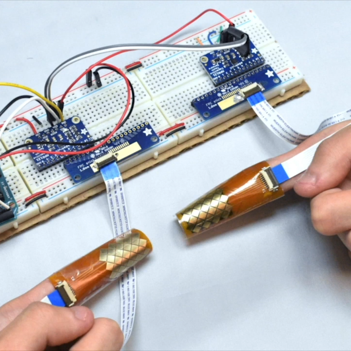
The fingertips are covered in touch sensors, each intended to be tapped by the thumbtip of the same hand.

Touch-typing with thumbs on a mobile phone keyboard is a pretty familiar way to input text, and that is part of what led to BiTipText, a method of allowing bimanual text input using fingertips. The idea is to treat the first segments of the index fingers as halves of a tiny keyboard, whose small imaginary keys are tapped with the thumbs. The prototype shown here was created to see how well the concept could work.

The prototype hardware uses touch sensors that can detect tap position with a high degree of accuracy, but the software side is where the real magic happens. Instead of hardcoding a QWERTY layout and training people to use it, the team instead ran tests to understand users’ natural expectations of which keys should be on which finger, and how exactly they should be laid out. This data led to an optimized layout, and when combined with predictive features, test participants could achieve an average text entry speed of 23.4 words per minute.

Judging by the prototype hardware, it’s understandable if one thinks the idea of fingertip keyboards may be a bit ahead of its time. But considering the increasingly “always on, always with you” nature of personal technology, the goal of the project was more about investigating ways for users to provide input in fast and subtle ways. It seems that the idea has some merit in principle. The project’s paper can be viewed online, and the video demonstration is embedded below.

One interesting thing is this: the inertia of users being familiar with a QWERTY layout is apparent even in a forward-thinking project like this one. We covered how Dvorak himself struggled with people’s unwillingness to change, even when there were clear benefits to doing so.

[via Arduino Blog]

Colorful, Touch-Sensitive Light Table is Ready for Gaming

It’s an ambitious build for sure — you don’t start with $500 worth of wood if you don’t intend for the finished product to dazzle. And this 240-pixel touch-sensitive light box coffee table does indeed dazzle.

Sometimes when we see such builds as these, fit and finish take a back seat to function. [dasdingo89] bucks that trend with a nicely detailed build, starting with the choice of zebrawood for the table frame. The bold grain and the frosted glass top make for a handsome table, but what lurks beneath the glass is pretty special too. The 240 WS2812 modules live on custom PCBs, each thoughtfully provided with connectors for easy service. There’s also an IR transmitter-receiver pair on each board to detect when something is placed over the pixel. The pixel boards are connected to custom-built shift register boards for the touch sensors, and an Arduino with Bluetooth runs the whole thing. Right now the table just flashes and responds to hand gestures, but you can easily see this forming the basis of a beautiful Tetris or Pong table.

This build reminds us a little of this pressure-sensitive light floor we featured recently, which also has some gaming possibilities. Maybe [dasdingo89] and  [creed_bratton_] should compare notes and see who can come up with the best games for their platform.

[via r/DIY and a tip from emptycanister]


Filed under: Arduino Hacks, led hacks

Sleek Desk Lamp Changes Colors Based on Sun Position

[Connor] was working on a project for his college manufacturing class when he came up with the idea for this sleek desk lamp. As a college student, he’s not fond of having his papers glowing brightly in front of him at night. This lamp takes care of the problem by adjusting the color temperature based on the position of the sun. It also contains a capacities touch sensor to adjust the brightness without the need for buttons with moving parts.

The base is made from two sheets of aluminum and a bar of aluminum. These were cut and milled to the final shape. [Connor] found a nice DC barrel jack from Jameco that fits nicely with this design. The head of the lamp was made from another piece of aluminum bar stock. All of the aluminum pieces are held together with brass screws.

A slot was milled out of the bottom of the head-piece to make room for an LED strip and a piece of 1/8″ acrylic. This piece of acrylic acts as a light diffuser.  Another piece of acrylic was cut and added to the bottom of the base of the lamp. This makes for a nice glowing outline around the bottom that gives it an almost futuristic look.

The capacitive touch sensor is a pretty simple circuit. [Connor] used the Arduino capacitive touch sensor library to make his life a bit easier. The electronic circuit really only requires a single resistor between two Arduino pins. One of the pins is also attached to the aluminum body of the lamp. Now simply touching the lamp body allows [Connor] to adjust the brightness of the lamp.

[Connor] ended up using an Electric Imp to track the sun. The Imp uses the wunderground API to connect to the weather site and track the sun’s location. In the earlier parts of the day, the LED colors are cooler and have more blues. In the evening when the sun is setting or has already set, the lights turn more red and warm. This is easier on the eyes when you are hunched over your desk studying for your next exam. The end result is not only functional, but also looks like something you might find at that fancy gadget store in your local shopping mall.


Filed under: Arduino Hacks

Fruit piano uses a different circuit than the Makey Makey

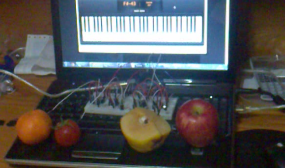
[Hasbi Sevinç] is using perishable goods in his electronics project. The orange, tomato, and two apples seen above act as keys for the virtual piano. The concept is the same as the Makey Makey which is often demonstrated as a banana piano. This implementation uses an Arduino to read the sensors and to connect to the computer running the piano program.

You can see there’s a fair amount of circuitry built on the breadboard. Each piece of fruit has its own channel to make it into a touch sensor. The signal produced when your finger contacts the food is amplified by transistors connected in a Darlington pair. That circuit drives the low side of a optoisolator transmitter. The receiving side of it is connected the I/O pin of the Arduino. You can see the schematic as well as a demo clip after the break.

This use of hardware frees up a lot of your microcontroller cycles. That’s because projects like this banana piano use the timers to measure RC decay. [Hasbi's] setup provides a digital signal that at most only needs to be debounced.


Filed under: arduino hacks, peripherals hacks