It has an SPI interface, it is powered by 5V, character set is defined and stored internally.
A quick search produced a sketch and documentation for the driver, PT6302.
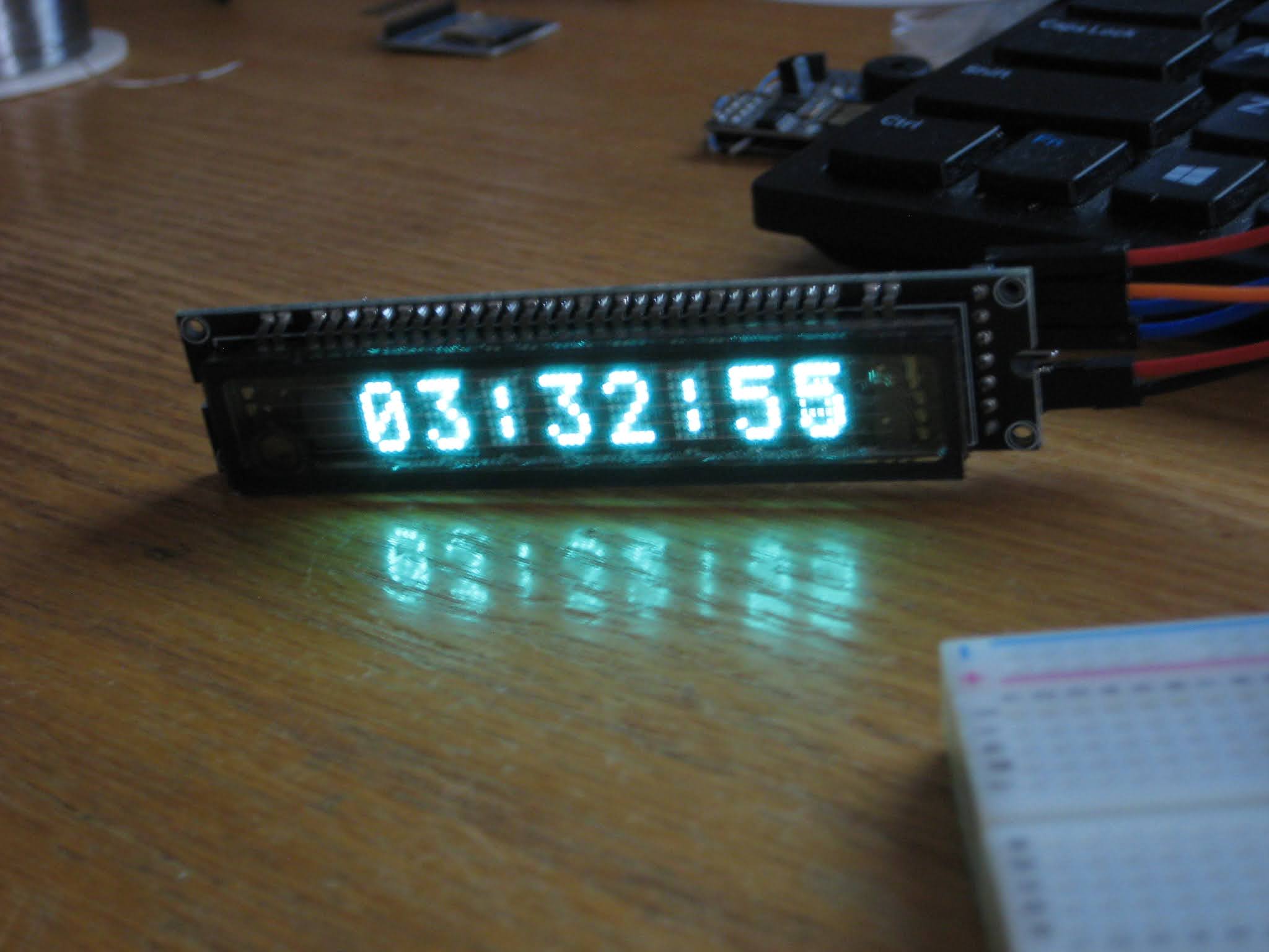
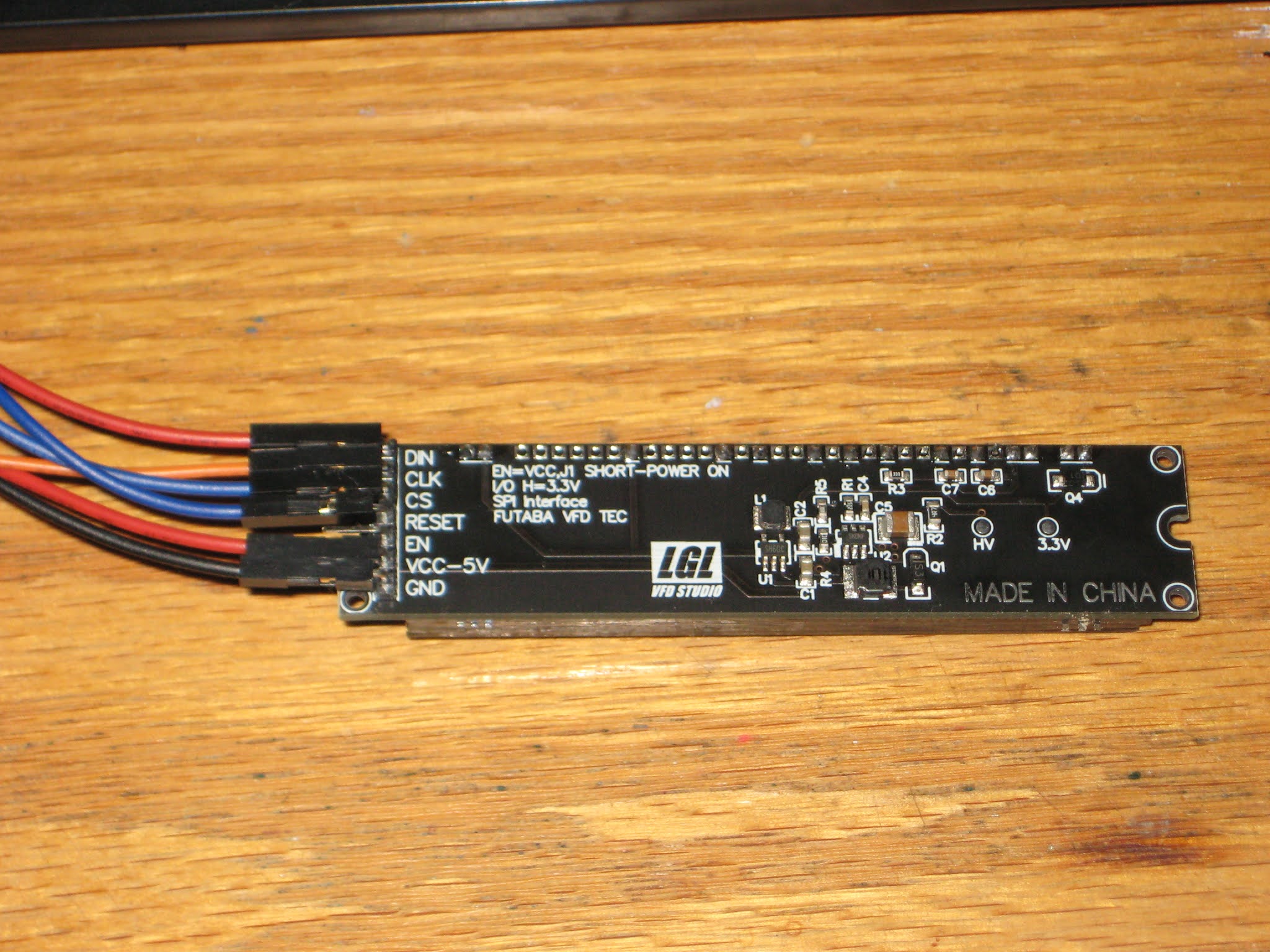
According to the PCB silkscreen, the VFD module is powered by 5V, but the signals are 3V3. (The 30V required by the VFD glass itself is made by the on-board switching mode power supply, so no need to worry about generating high voltage externally.) An ESP32 board would be the perfect candidate to control this display. Luckily, the found sketch was also written for ESP32, so all I had to do was compile and upload using Arduino IDE 1.8.13. The only problem was that my IDE installation did not show ESP32 boards anymore, even though I used it once previously. Therefore, I had to re-visit the whole setup process once again. This time I am documenting it, to save on any future effort. So here are the steps:
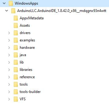
install Arduino IDE (1.8.13, in my case) from Windows store, placed here:
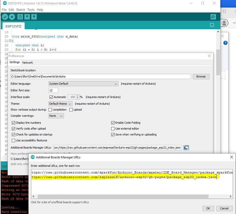
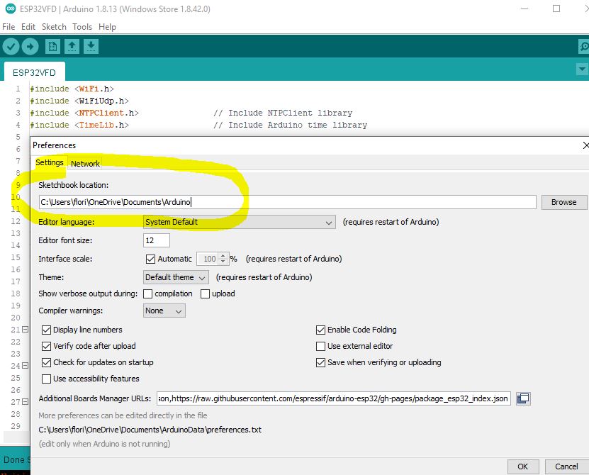
add the ESP32/expressif package URL for the Boards Manager, as nicely explained here; essentially, select menu File -> Preferences, then add line
install the set of ESP32 boards in "Boards Manager"; menu Tools -> Boards Manager:
select the proper board for the ESP32-WROOM dev kit that I used; menu Tools -> Boards Manager -> ESP32 Arduino -> Node32s;
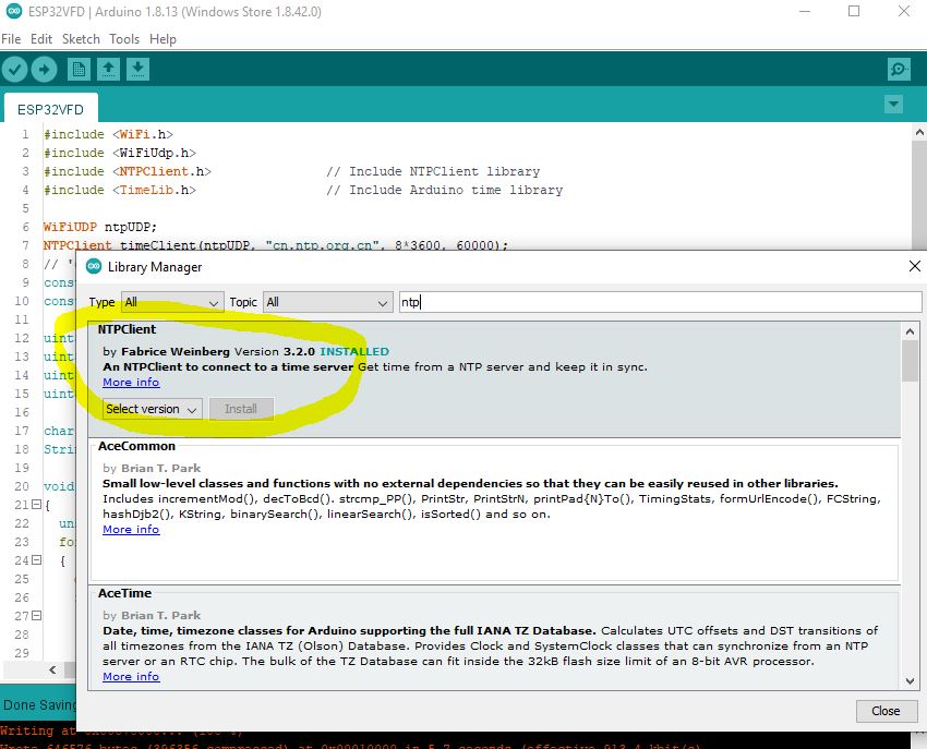
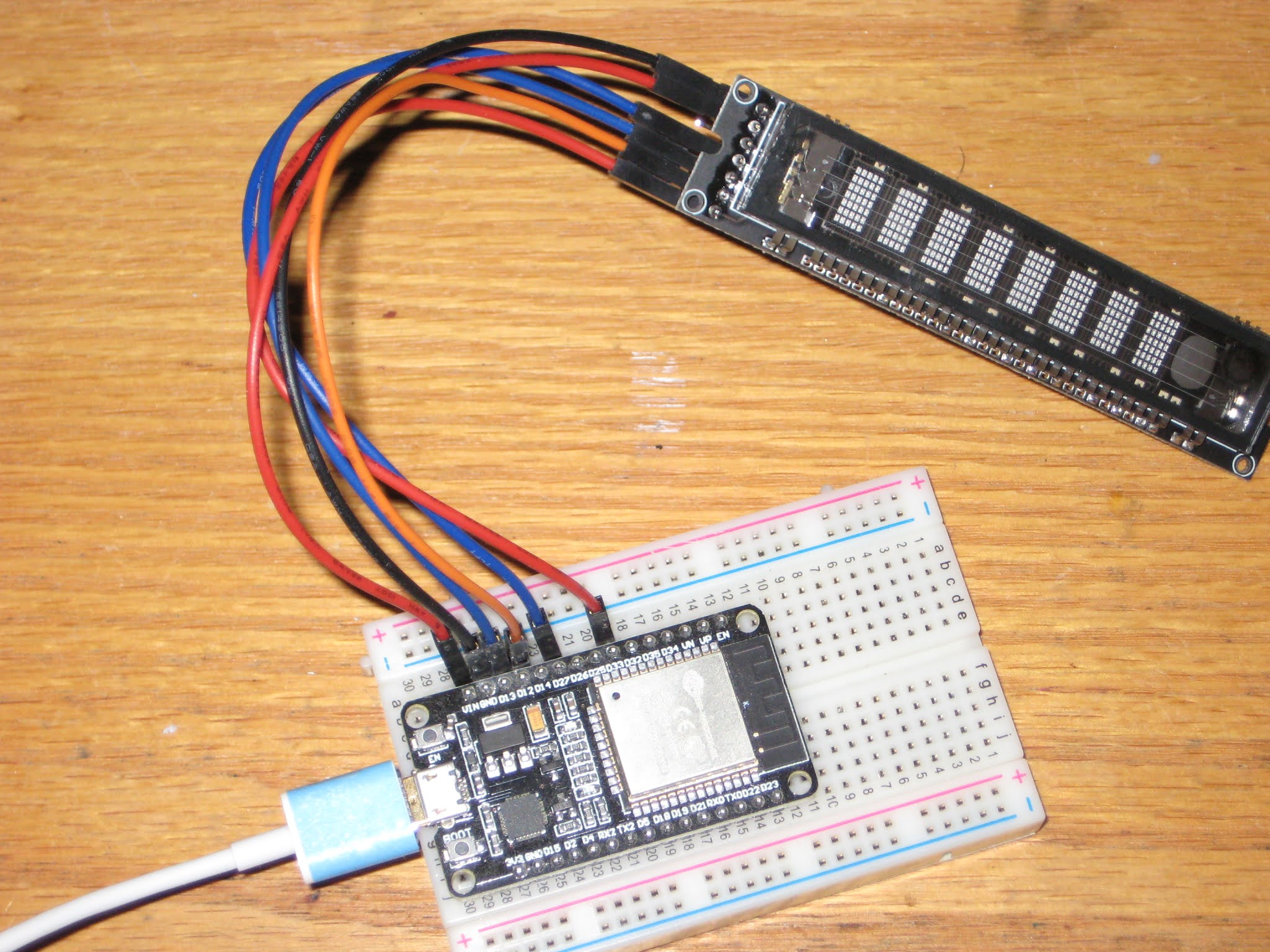
open the sketch, then modify the SPI pins (I used DIN=33, CLK=12, CS=13, RST=27, all on the same side of the ESP32 dev module); got compilation error "Library not found" for both NTPClient and TimeLib;
install the missing libraries, through menu Tools -> Manage Libraries...
The 2 libraries have been installed here
at the location specified in File -> Preferences:
compile, then upload successfully.
Surprisingly easy, straightforward and without glitches, this must have been the easiest ever first-time interfacing with a device.
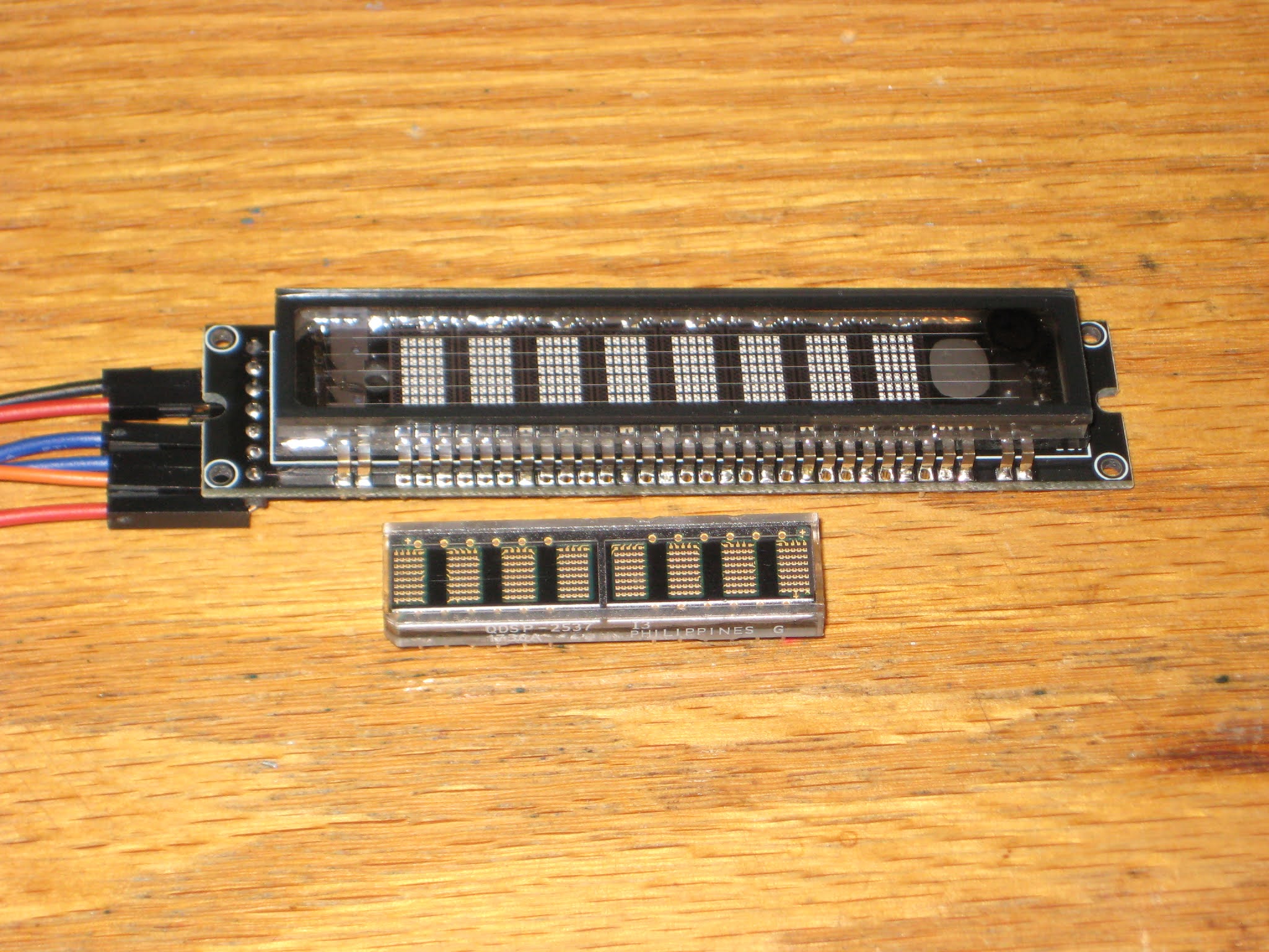
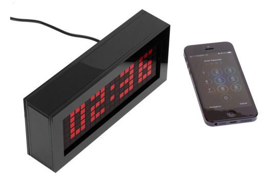
Compared to the HDSP-2534 LED display, the characters in the VFD module are about 50% bigger, and much brighter, making it readable from a greater distance. The current consumption is in the range 100-200mA, versus about 20mA taken by the HDSP display.
Also, at just about US$13, this (yet unnamed, or maybe Futaba?, see photo below) VFD display makes a great functional alternative for the more expensive HDSP/Avago/Siemens/Osram 8-character LED displays.
reasonably priced (this is relative; what may be expensive for me may be cheap for you)
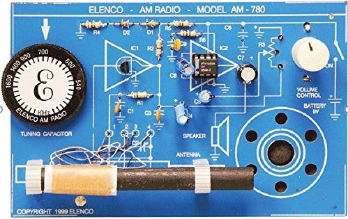
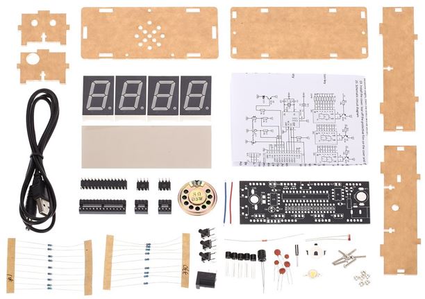
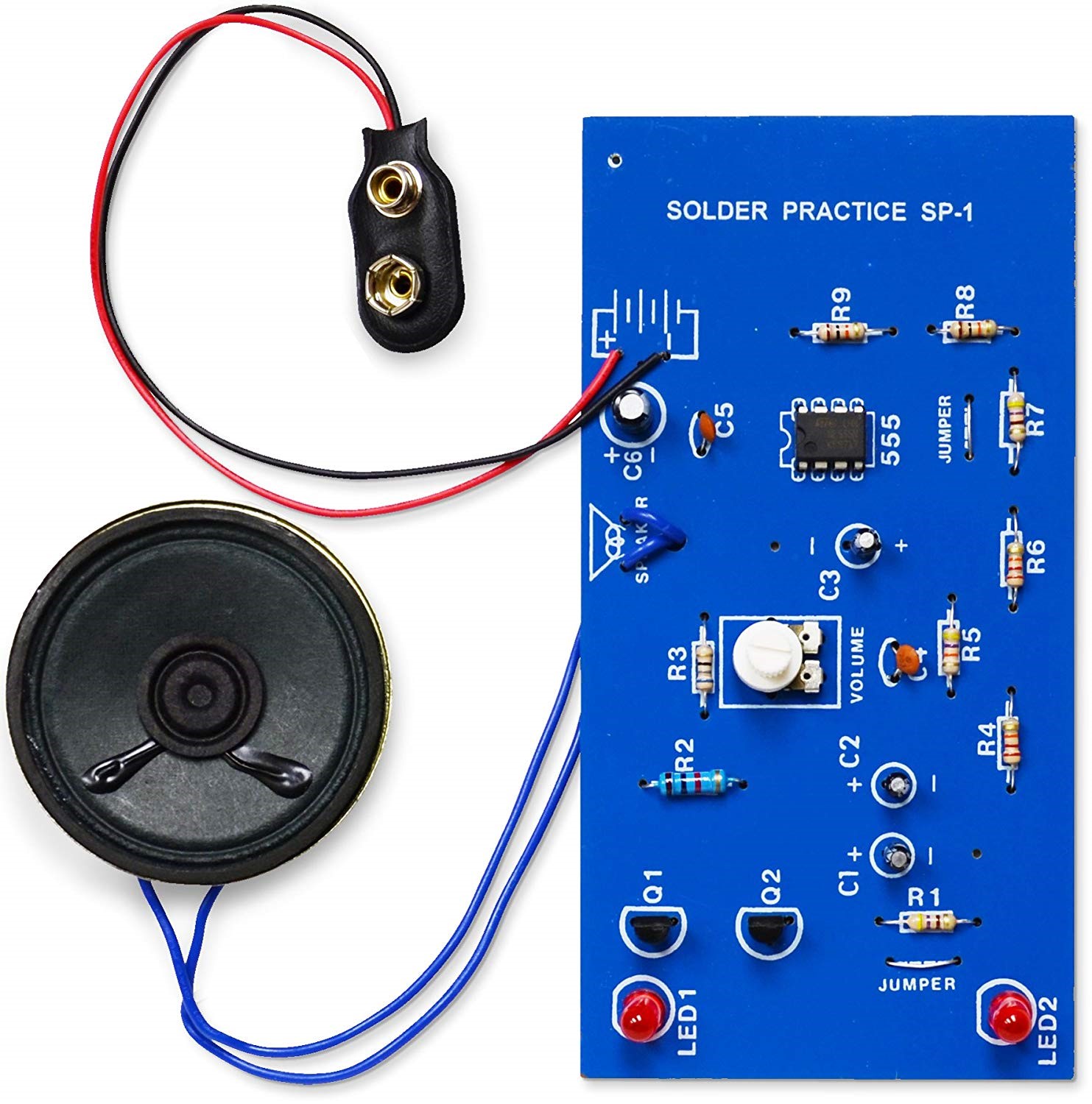
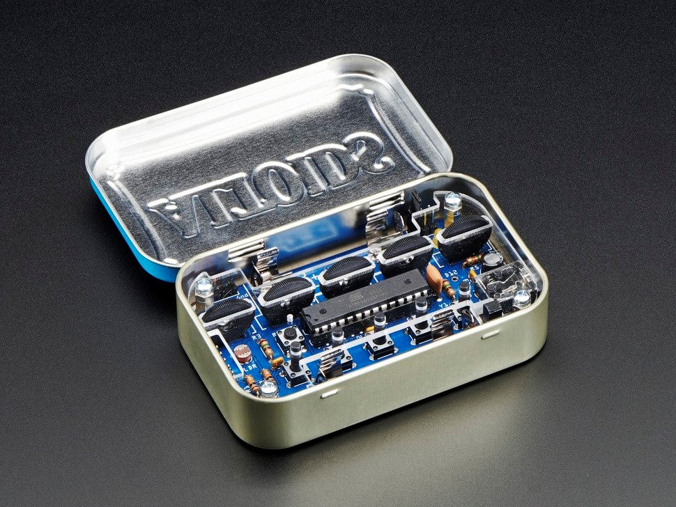
standalone and all-inclusive: does not require extra parts/components/modules sourced from third parties and does not require loading software;
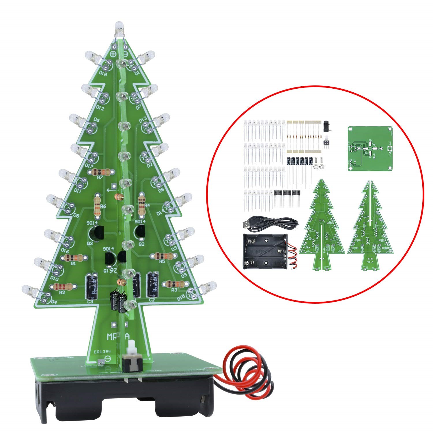
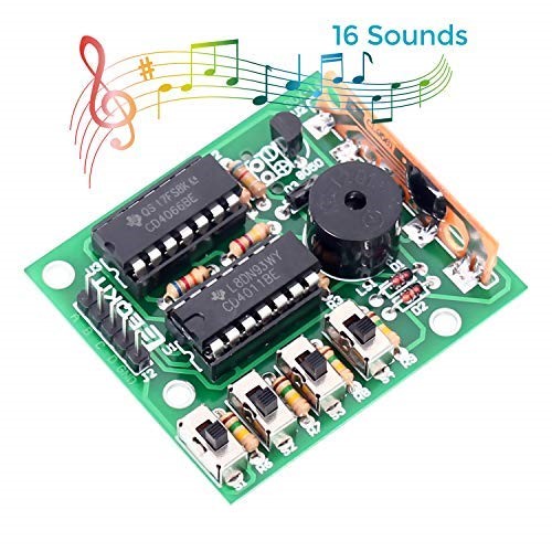
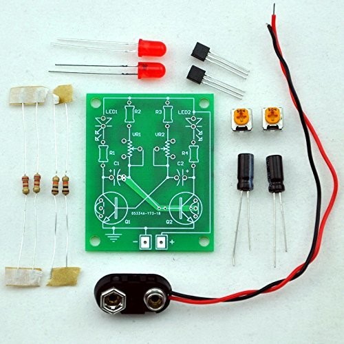
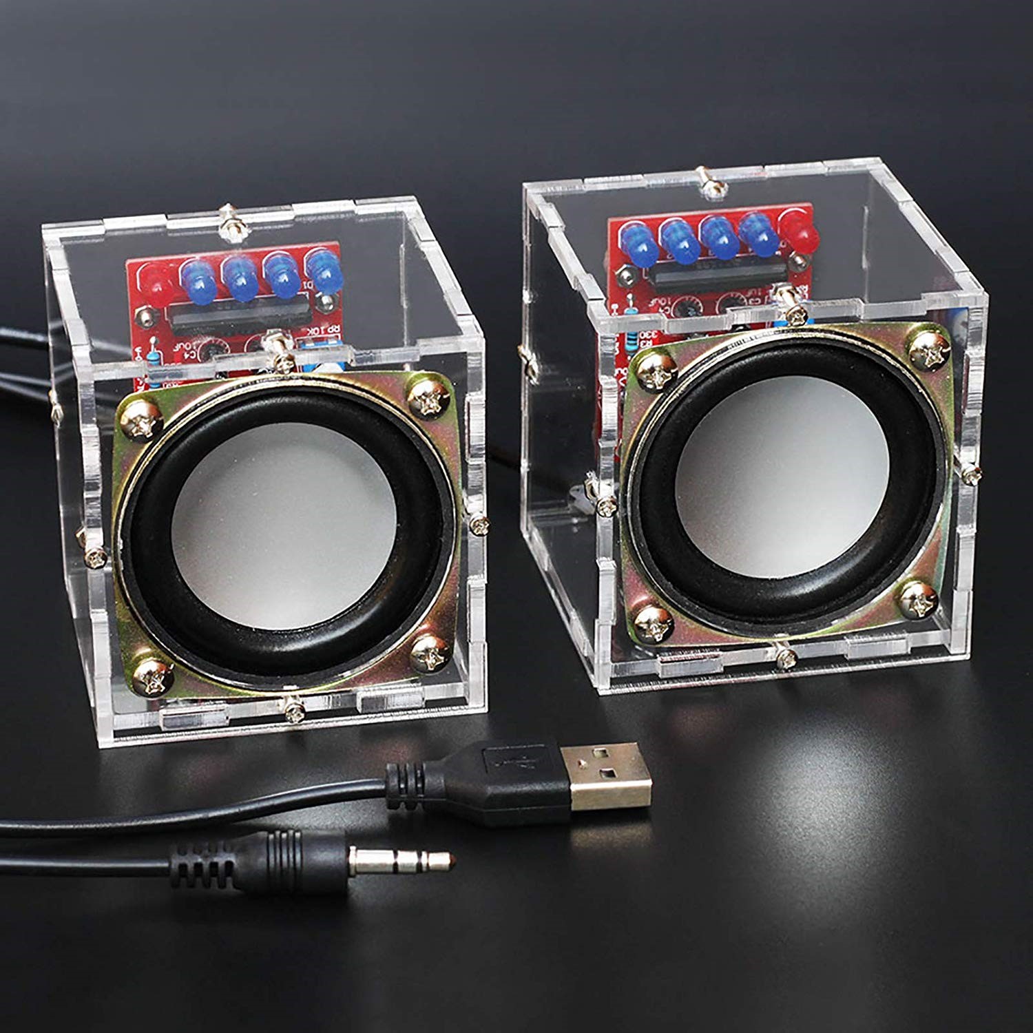
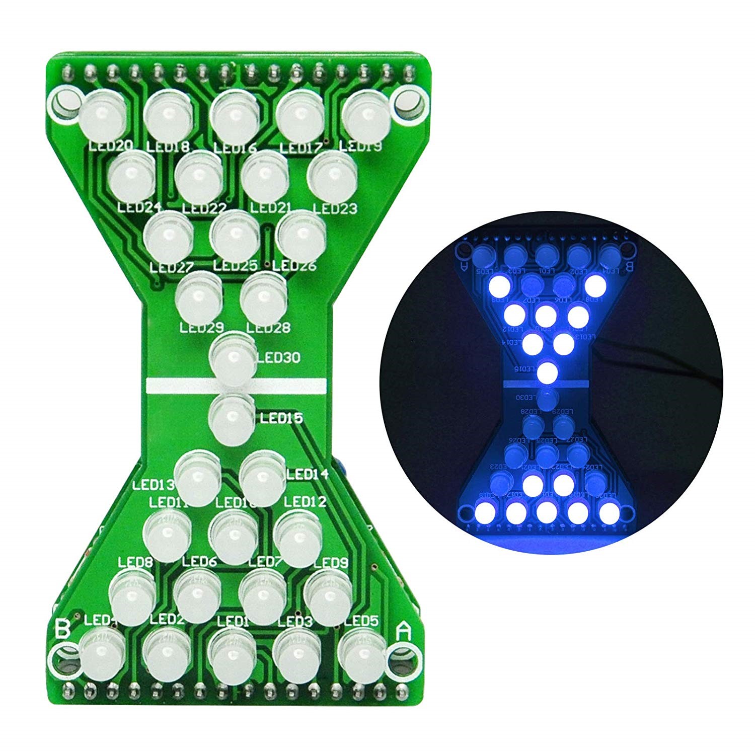
interesting (as opposed to boring) functionality: flashes LEDs, displays something on a screen, makes some sounds etc.
relative simplicity of the circuit, so it can be easy to understand and debug if necessary
aesthetics of the board (shape, colour, component placement etc.)
preferably open source
powered by low voltage (battery, USB, power adapter)
digital electronics rather than analog (easier to debug, if necessary)
practical utility: use it for a utilitarian purpose rather than forget about it once built
expandability: can be either integrated as part of a bigger project, or its capabilities and functionality can be extended by adding modules or parts
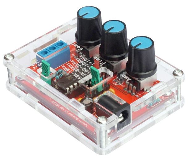
provides extra learning (besides soldering) by displaying information: wave forms, frequencies, binary/hex number representation, musical notes, proverbs etc.
satisfaction guaranteed once assembled and working :)
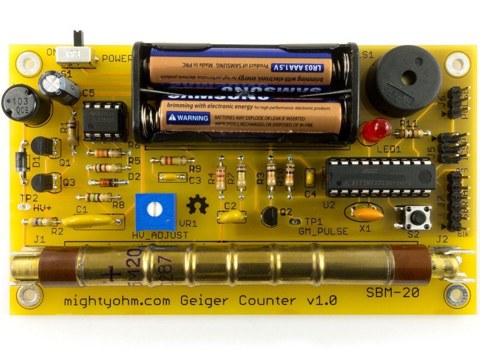
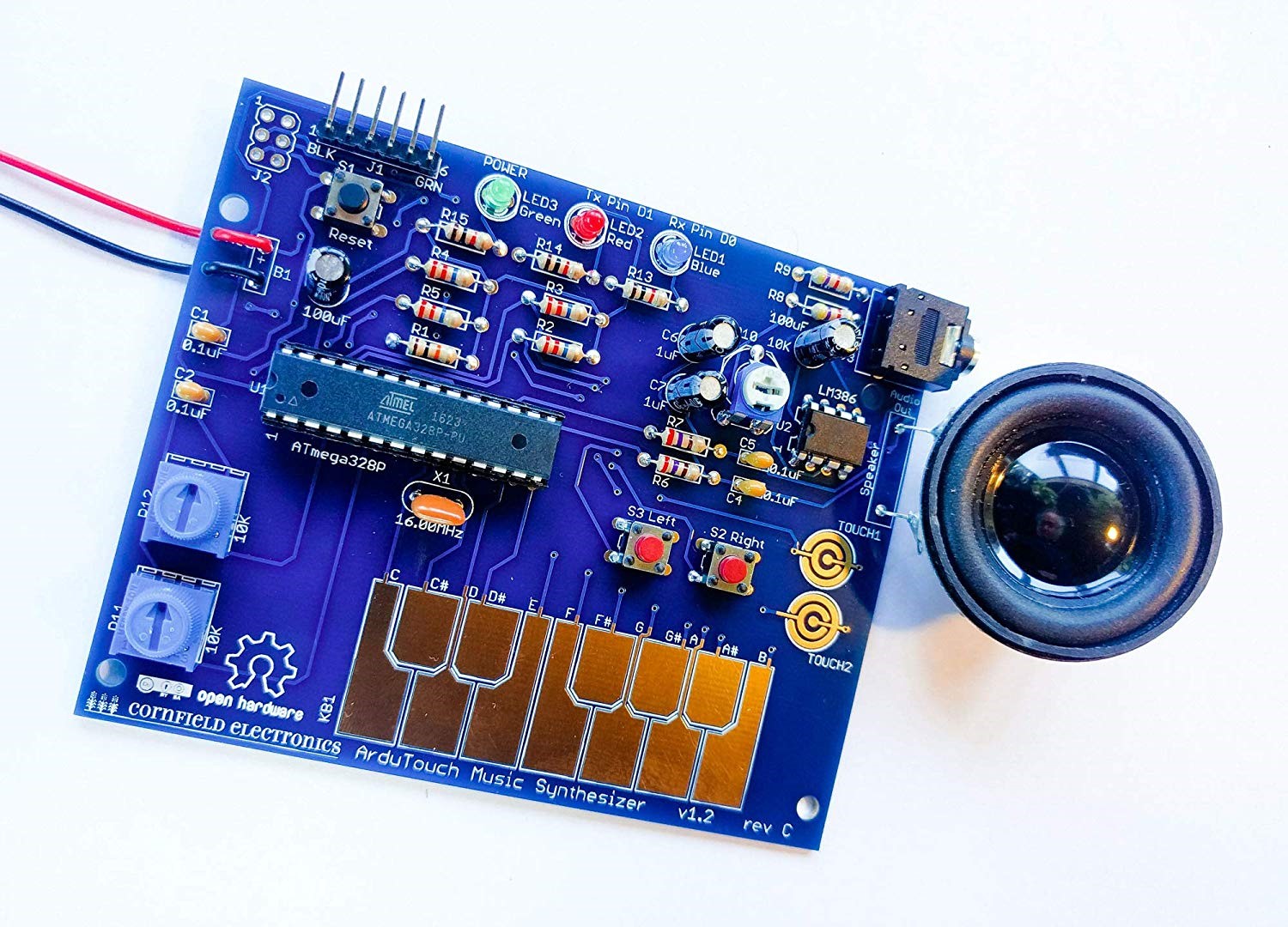
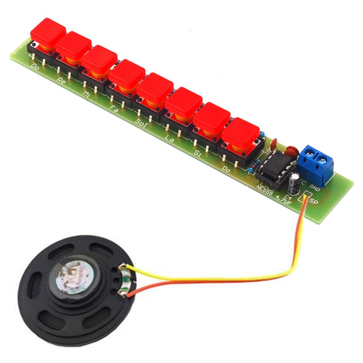
Here is a list, in no particular order, of beginner kits I found to match some of the above criteria.
reasonably priced (this is relative; what may be expensive for me may be cheap for you)
standalone and all-inclusive: does not require extra parts/components/modules sourced from third parties and does not require loading software;
interesting (as opposed to boring) functionality: flashes LEDs, displays something on a screen, makes some sounds etc.
relative simplicity of the circuit, so it can be easy to understand and debug if necessary
aesthetics of the board (shape, colour, component placement etc.)
preferably open source
powered by low voltage (battery, USB, power adapter)
digital electronics rather than analog (easier to debug, if necessary)
practical utility: use it for a utilitarian purpose rather than forget about it once built
expandability: can be either integrated as part of a bigger project, or its capabilities and functionality can be extended by adding modules or parts
provides extra learning (besides soldering) by displaying information: wave forms, frequencies, binary/hex number representation, musical notes, proverbs etc.
satisfaction guaranteed once assembled and working :)
Here is a list, in no particular order, of beginner kits I found to match some of the above criteria.
My "Introduction to Practical Electronics for Children" course concluded successfully a few weeks back, before March break. Now, with schools closed for covid19, it would be a good time for the kids to practice soldering and learn by doing. At this stage, I think it is easy to expand their knowledge and skills in the field of electronics just by assembling kits.
Here are a few notes and observations from my teaching.
Each class had 6 groups of 3 students sharing a soldering station. This (not my decision) was probably based of space constraints (6 desks in a normal-sized classroom) and safety/supervision considerations. It worked pretty well: the 2 students (in each group) not soldering had time to observe, analyze, think and to ask lots of questions. Two professional teachers assisted, with supervision, helping the students and keeping discipline.
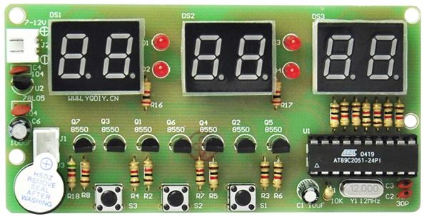
Each student had their own "HDSP clock" kit to assemble. It took 6 one-hour sessions to complete, with a success rate of about 95% (2 failures out of 38 assembled, because of solder bridges).
The intended "50% theory and 50% practice" ratio had quickly become 10/90. Still managed to introduce components (resistor, capacitor, crystal), electrical concepts (AC vs DC, voltage, resistance, current, frequency) and units of measures (Volts, Farads, Ohms, Hertz). We even talked about Tesla batteries :)
Some parts were lost (e.g. crystal) or damaged (dropped, then stepped on by accident) between or during the classes. The lesson learned is to have extras available.
Each student received individual instructions, guidance, assistance and supervision on soldering. We came up with the "3-second rule" to make a good soldering joint: hold the tip of the soldering iron in contact with the pad and the terminal for 3 seconds while touching and melting the solder wire on the tip.
Having students pay attention to the instructions was very important. It saves energy to talk once to the whole class, rather than answering the same question to each individual. (I also learned from professional teachers the "1-2-3 eyes on me" attention-getter.)
Sockets for integrated circuits are a must in a beginner kit. Imagine fixing an IC soldered in the wrong orientation! (The "worst" that happened was that all 3 ICs in the kit were soldered directly onto the board, luckily in the correct orientation.) Also, silkscreen should be as detailed as possible, indicating the component's place. In case of the "HDSP clock" kit, the students were able to easily identify the placeholders for each component, just by using logic (except for the resistors; they learned quickly to bend the resistors' terminals).
Some of the most frequent mistakes were soldering bridges and filling empty holes with solder. Bridges were easily fixed (initially by me, then the students learned to do it themselves) using the copper wick/braid, and flux. To fix the solder-filled holes, I had to use a tailor pin (part of my EDC Swiss card).
Surprisingly, every student showed interest in working on, and completing, the kit. I think it was a successful experiment even for the school, in making "practical electronics" as part of their curriculum. Like in the old days of practical skills teaching (wood working for boys, sewing or cooking for girls), this course demonstrated that Grade 6 students are very capable and eager to acquire skills that may stay with them for life.
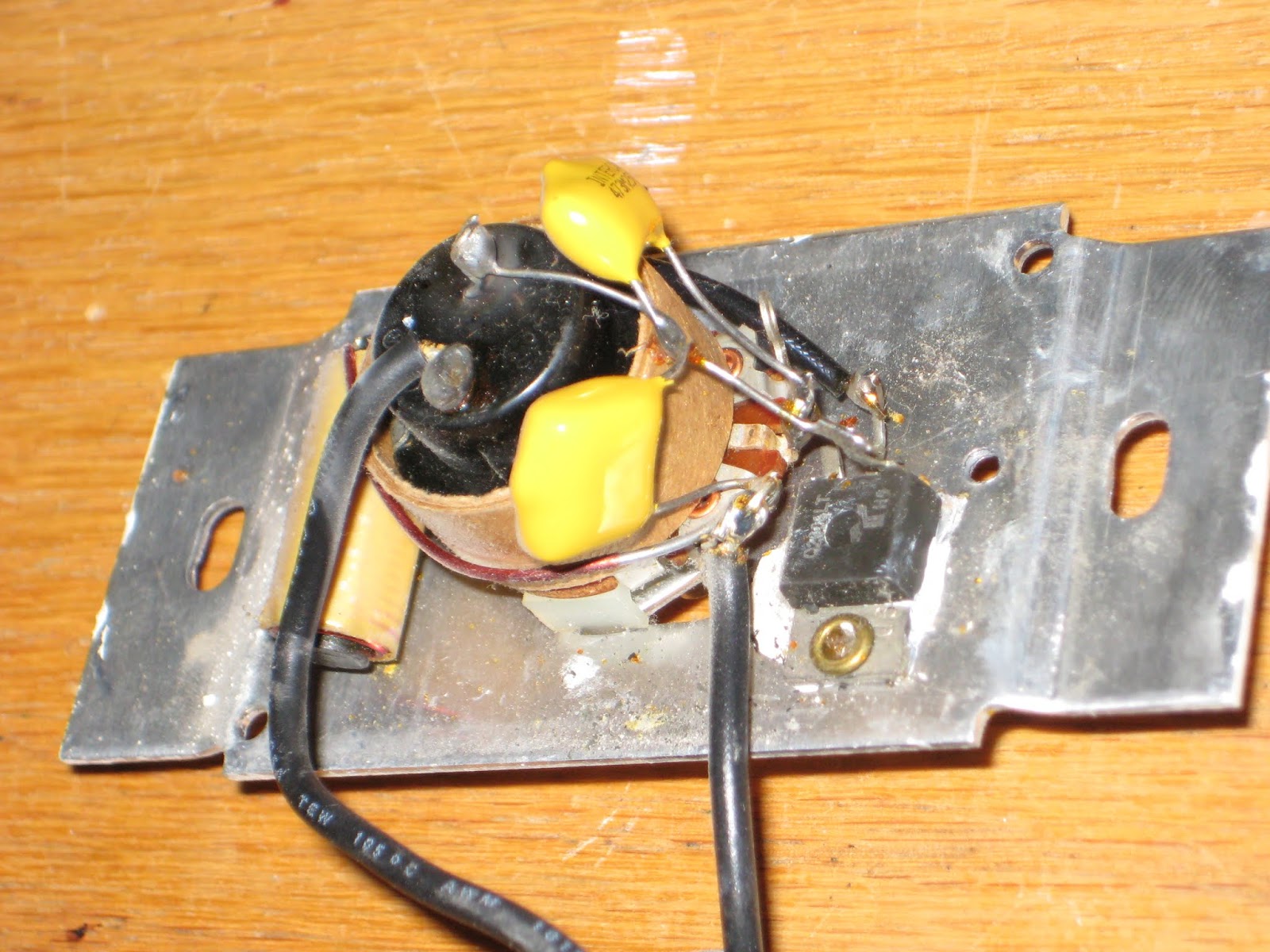
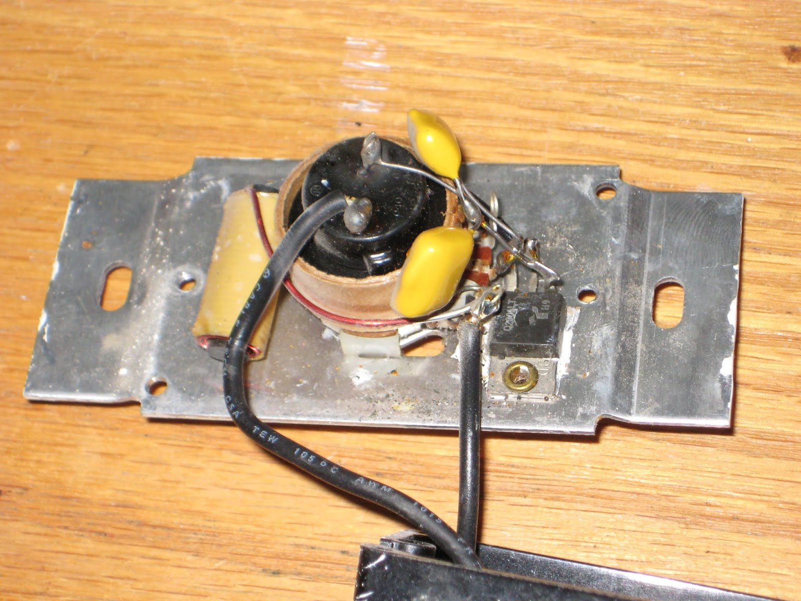
The 40+ year-old dimmer (made by Nortron Industries Limited in Milton, Ontario) in my attic broke down. Electronically, the dimming circuit still worked, but mechanically, the push button got stuck. This is what's inside, for the curious.
The active component in the circuit is Q2006LT, a "quadrac" which, according to the datasheet, "is an internally triggered Triac designed for AC switching and phase control applications. It is a Triac and DIAC in a single package, which saves user expense by eliminating the need for separate Triac and DIAC components".
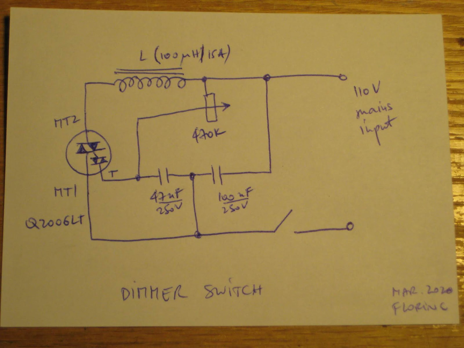
The "reversed-engineered" schematic looks like this:
For those who want to understand more on how the triac-controlled dimmer works, this article provides an in-depth explanation.
The 250V capacitors may be reused in a Nixie high-voltage (~170V) power source. For a hoarder, both the choke and the potentiometer (push button removed) look good.
I will report back on the internals of the replacement switch in 40 years or so, when it breaks down. I hope I/it last(s) that long.
The 40+ year-old dimmer (made by Nortron Industries Limited in Milton, Ontario) in my attic broke down. Electronically, the dimming circuit still worked, but mechanically, the push button got stuck. This is what's inside, for the curious.
The active component in the circuit is Q2006LT, a "quadrac" which, according to the datasheet, "is an internally triggered Triac designed for AC switching and phase control applications. It is a Triac and DIAC in a single package, which saves user expense by eliminating the need for separate Triac and DIAC components".
The "reversed-engineered" schematic looks like this:
For those who want to understand more on how the triac-controlled dimmer works, this article provides an in-depth explanation.
The 250V capacitors may be reused in a Nixie high-voltage (~170V) power source. For a hoarder, both the choke and the potentiometer (push button removed) look good.
I will report back on the internals of the replacement switch in 40 years or so, when it breaks down. I hope I/it last(s) that long.
I designed this 7-hour (one hour/day) course for 6 graders, as part of their STEM curriculum. The goal is to introduce the children to practical electronics and teach them about:
1. electronic parts/components: how to identify/recognize them, how to measure (using a multi-meter), what they are used for (role in an electronic circuit):
2. how to solder (using a soldering station), how to place and position parts on a board, how to check connection, how to follow steps of an instruction manual;
3. electricity and electronics concept:
voltage, current, resistance;
AC vs DC
digital vs analog
oscillation
rectification
amplification
series, parallel
voltage transformation (AC)
voltage regulation (AC, DC)
4. basic understanding/reading of schematics (wiring, electrical connections).
optional: panavise/third hand, power supplies, wires, connectors;
Course schedule
Day 1 theory: introduction to components; presentation and identification (1/2 hour) practice: beginning soldering (1/2 hour) LED + resistor, using flux, soldering wire, wick, on prototype PCBs; Day 2 theory: introduction of a simple clock kit or another, more familiar to me, simple HDSP clock kit; assembly analysis, component placement and positioning; practice: solder passive components on PCB; assemble the HDSP clock; Day 3 theory: more on components; introduction to schematics; practice: solder the active components of the clock kit; Day 4 theory: electricity concepts (digital vs analog); practice: finishing up the kit assembly; power, test, use;
Day 5 theory: electricity concepts (voltage, current, resistance); example of other kits; practice: learn to use an ohm/volt/meter;
Day 6 theory: electronics concepts (oscillation, rectification, amplification, sound generation etc.); practice: bring an electronic toy, working or not; disassembly, analysis, repair (if needed);
Day 7 practice: continuation from Day 6; identification of components used in the toy; understanding of how it works; modding/expanding functionality/adding LEDs, speaker, buttons etc.;
We are already on "Day 3", but behind schedule. Soldering is harder for the kids than I originally thought. One thing that I overlooked was that each student needs individual attention/supervision on the practical side (soldering, component placement etc.). Half hour per day of hands-on practice is definitely too short at this level. The schedule may be a little aggressive for the average Grade 6, probably better suited for older and more disciplined students. In any case, I am working on adjusting the content of the course and the feedback I receive is amazing. Kids really enjoy the fact that it is practical and some of them are amazed when they see the LEDs they soldered actually lighting up.
A while back, I wrote an article about Malduino, an Arduino-based, open-source BadUSB device. I found the project interesting so I signed up for an Elite version and sure enough, the friendly postman dropped it off in my mail box last Friday, which means I got to play around with it over the weekend. For those who missed the article, Malduino is USB device which is able to emulate a keyboard and inject keystrokes, among other things. When in a proper casing, it will just look like a USB flash drive. It’s like those things you see in the movies where a guy plugs in a device and it auto hacks the computer. It ships in two versions, Lite and Elite, both based on the ATmega32U4.
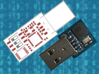
The Lite version is really small, besides the USB connector it only contains a switch, which allows the user to choose between running and programming mode, and a LED, which indicates when the script has finished running.
Original Malduino Elite sketch and Lite prototype
The Elite version is bigger, comes with a Micro-SD card reader and four DIP switches, which allow the user to choose which script to run from the card. It also has the LED, which indicates when a script has finished to run. This allows the user to burn the firmware only once and then program the keystroke injection scripts that stored in the Micro-SD card, in contrast to the Lite version which needs to be flashed each time a user wants to run a different script.
These are the two Malduinos and because they are programmed straight from the Arduino IDE, every feature I just mentioned can be re-programmed, re-purposed or dropped all together. You can buy one and just choose to use it like a ‘normal’ Arduino, although there are not a lot of pins to play around with. This freedom was one the first things I liked about it and actually drove me to participate in the crowd-funding campaign. Read on for the full review.
The Hardware
Malduino Elite vs USB flash drive
So the Elite board arrived as schedule and I found myself some time to look an it. Despite being longer than the Lite version, it’s still quite small, measuring roughly 4.6 cm x 1.1 cm (around 1.8 in x 0.43 in), which you can easily adapt to an old USB case, although you’ll have to cut some holes for the DIP switches and the Micro-SD card. In the crowd-funding campaign, the original sketch was for a 3 DIP switch version but the final Elite has four, which I found nice. I plugged it in to an old computer, after some consideration about which firmware it could ship with and what it could do to my laptop, and sure enough a red LED appeared. And that was it. Nothing else.
After playing around with the switches and exercising some RTFM, I realised that the firmware it ships with is probably some sort of Q.C. test for the dips, which makes the Malduino output the numbers 1 to 4 (actually simulating a keypress 1 to 4), depending on which switches are ON. So far so good, it works and I’ve seen worse PCB boards than this one. The board has holes for six pins, which I did not trace to the micro-controller and I don’t know what they are for.
The Setup
Setting up the Malduino requires that you have the Arduino IDE installed and up to date. You’ll need to open up the board manager and install the Sparkfun boards since the Elite is programmed as a ‘Sparkfun Pro Micro’ running at 3.3 V and 8 MHz. Then you need to go the Malduino Script Converter website which serves several purposes:
It allows to convert scripts between the Lite and Elite versions
It allows you to choose your keyboard layout language
It auto generates the Arduino project for you to import to the IDE
For the Elite version, just create a simple or even empty script to download the project, since when in ‘normal’ operation you will just flash the Malduino once and then use the Micro-SD card to store new scripts.
A note on flashing, if you are using a Debian-based distribution you might come across some problems like I did and not be able to flash the device. Like the user on this most useful post, my modem-manager was trying to talk with the Malduino after every reset and confused AVRDUDE to death. The solution is to add udev rules to “/etc/udev/rules.d/77-mm-usb-device-blacklist-local.rules”, kudos to [socrim]:
Since I’m running Linux, a quick shortcut to run a command is the ALT-F2 combination. So I script that into a file and save it to 1111.txt. The Elite searches the Micro-SD card for a file corresponding to the current dip switch state. Lets say the dip switch 2 and 4 are ON. In this case, the software tries to find the file named 0101.txt and parse its contents (as in dip switch order 1,2,3,4 and not the binary representation of the number 2 and 4) . When it finishes, the red LED starts flashing quickly. My simple script was:
DELAY 2000
ALT F2
DELAY 1000
STRING xterm
DELAY 1000
ENTER
DELAY 1000
STRING id
DELAY 1000
ENTER
But it was not working. Almost all commands worked but the ALT-F2 combo was not functioning properly. Close, but no cigar. No ALT-F2, no run command window. I’ve already lazy-browsed the source code a bit because I really didn’t have a lot of time on my hands but I needed to figure this out. The offending code was this:
A custom equals function was receiving size 3 for the strings of the Function keys, like “F2”. It was ok for “F10”, “F11” and “F12”, but failed for the rest of the keys. Changing 3 to 2 did the trick, but my Portuguese keyboard layout started to interfere with other test scripts. So I changed the code to include PT and UK layouts, changing them in a #define at compile time.
It would be cool if it was possible to access the SD card from the computer as a regular USB volume. I don’t know exactly how feasible that is, but it does not come with the current firmware. I still wanted to be able to output the content of an arbitrary file on the SD card to the screen, so I added another script function called ECHOFILEHEX that outputs the content of a file in the SD card as escape characters. For example, if the file a.txt contains “AAA”, the script command ECHOFILEHEX a.txt would output “\x41\x41\x41”. This can be useful to echo binary files into printf or echo -e, in Linux hosts at least.
Meanwhile, I had some trouble reading the original code. You know, we all have different programming styles. Don’t get me wrong, I’ve been known to write some messed-up spaghetti code. I sometimes browse old projects looking for some libs or classes I coded and wonder ‘who the heck wrote this steaming pile of code?’ Me, it was me. Anyway, I started to change a bit here and there and ended up changing pretty much the entire code. That’s the beauty and the curse of open-source. If you’re curious you can check it out here.
Conclusion
All in all, and despite some bumps, I’m quite pleased with Malduino. It is what I expected: an open platform for BadUSB attacks that’s in its infancy. It’s awesome that we can all tinker with it, modify it, make it better or just make it suit our needs. I hope a real community can start so we can see its full potential emerge. My short list includes simulating other USB devices, better SD card management, and expanding the device via the unused pins. What would you add?
It’s a long way to go and a lot can go wrong, so good luck with the project [Seytonic]!
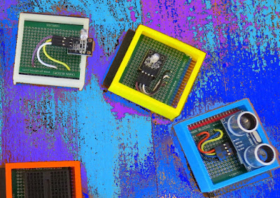
In this tutorial, I will be evaluating Prextron CHAIN blocks – a new system that allows you to connect your sensors and actuators to an Arduino NANO using clever 3D-printed prototyping boards that can be stacked sideways. This very modular system makes it easy to connect, disconnect and replace project components, and eliminate the “rats nest of wires” common to many advanced Arduino projects. CHAIN BLOCKS are open, which means that you can incorporate any of your sensors or actuators to these prototyping boards, and you can decide which specific pin on Arduino you plan to use. The CHAIN BLOCK connections prevent or reduce common connection mistakes, which make them ideal for class-room projects and learning activities.
I am going to set up a project to put these CHAIN BLOCKs to the test: When I place my hand in-front of an Ultrasonic sensor, the Arduino will transmit a signal wirelessly to another Arduino, and consequently turn on a motor.
Please note: You may need to solder the module wires to the CHAIN BLOCK protoboard.
Arduino Libraries and IDE
This project does not use any libraries. However, you will need to upload Arduino code to the Arduino. For this you will need the Arduino IDE which can be obtained from the official Arduino website: https://www.arduino.cc/en/main/software
ARDUINO CODE: RF Transmitter
ARDUINO CODE: RF Receiver
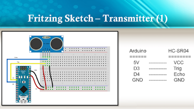
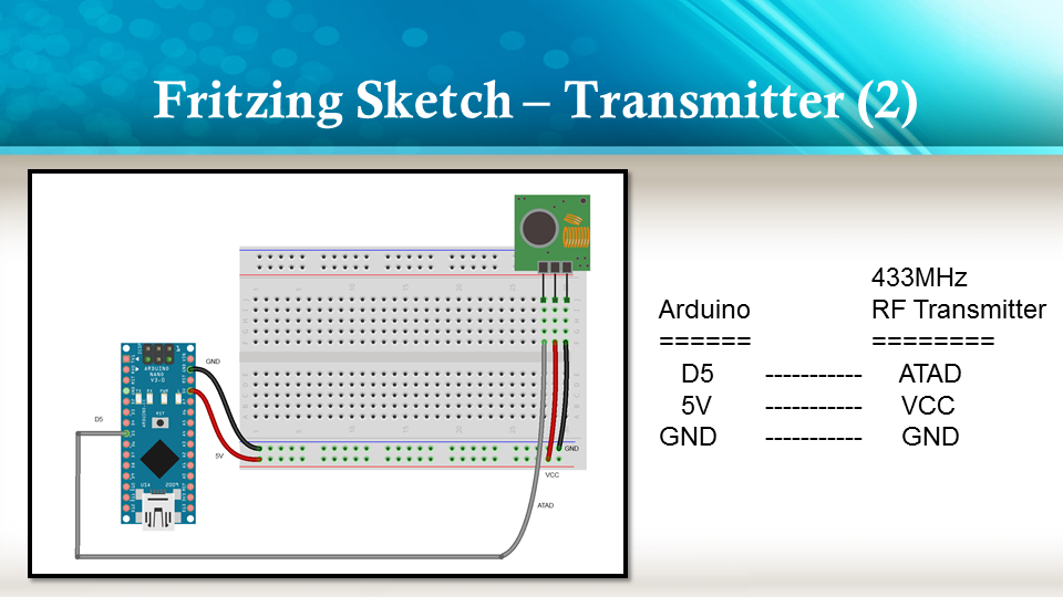
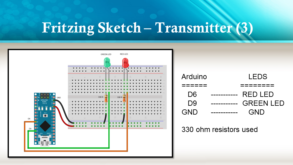
Fritzing diagrams for Transmitter
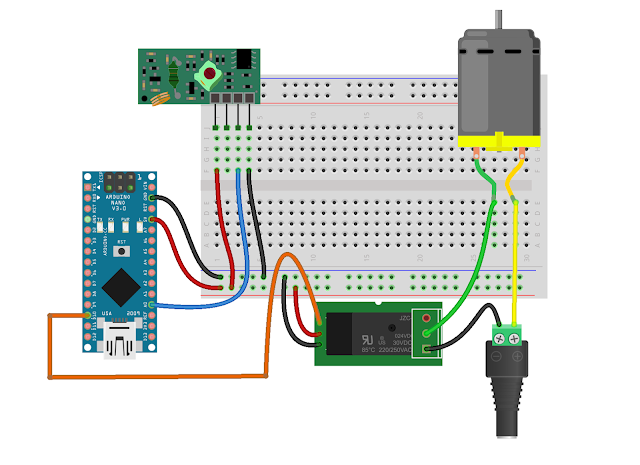
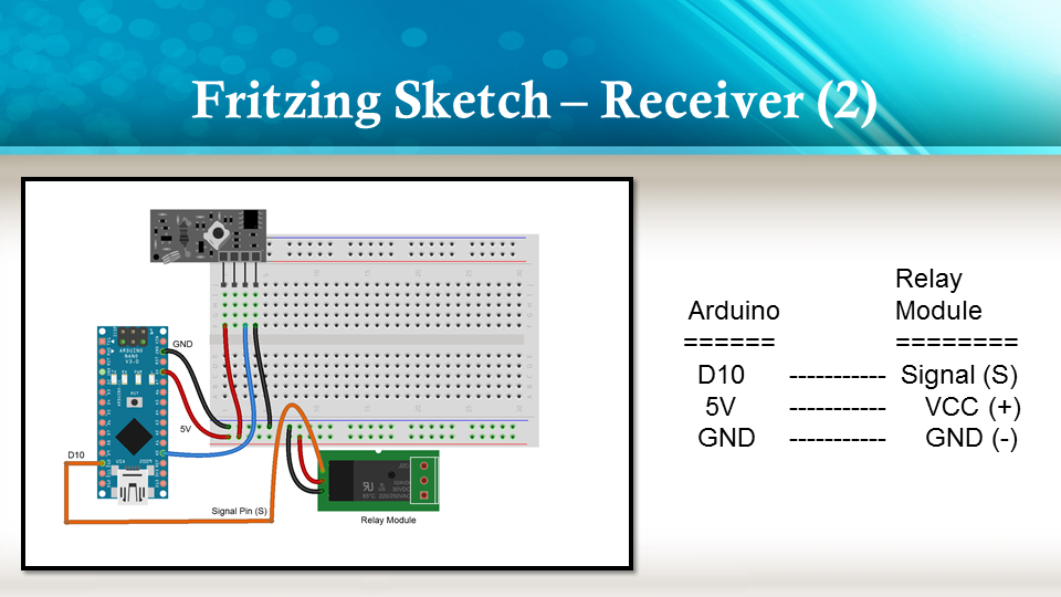
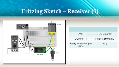
Fritzing diagrams for Receiver
Concluding comments
The purpose of this project was to evaluate Prextron CHAIN BLOCKs and put them to the test. Here is what I thought of CHAIN BLOCKS at the time of evaluation. Some of my points mentioned below may no longer apply to the current product. It may have evolved / improved since then. So please take that into consideration
What I liked about Chain Blocks
The design is simple, the product is simple.
Once the Chain Blocks were all assembled, they were very easy to connect to each other.
I can really see the benefit of Chain Blocks in a teaching environment, because it simplifies the connection process, and reduces connection mixups.
It was good to see that the blocks come in different colours, which means that you can set up different colour schemes for different types of modules.
You can incorporate pretty much any sensor or Actuator into the Chain block which is very appealing.
You also have the flexibility of choosing which pins you plan to use on the Arduino.
Projects look a lot neater, because you no longer have the rats nest of wires.
The Blocks lock into each other which means that they are much easier to transport/carry.
What I did not like about Chain Blocks
In most cases, the Chain Block protoboard lanes were not numbered, which increased the chances of making mistakes when soldering
The need to solder modules to the protoboard, may be a discouragement for some people.
I would have liked a choice of different size Chain blocks. Some of the sensors did not fit nicely into the Square blocks.
Prextron really need to work on their website if they plan to get serious with this product: Webpage has incomplete functionality or irrelevant links etc etc.
Thank you very much to Prextron for providing the CHAIN BLOCKS used in this tutorial, and allowing me to try out their product. If you are interested in trying them yourself, then make sure to visit them at:
If you like this page, please do me a favour and show your appreciation :
In this tutorial, I will be evaluating Prextron CHAIN blocks – a new system that allows you to connect your sensors and actuators to an Arduino NANO using clever 3D-printed prototyping boards that can be stacked sideways. This very modular system makes it easy to connect, disconnect and replace project components, and eliminate the “rats nest of wires” common to many advanced Arduino projects. CHAIN BLOCKS are open, which means that you can incorporate any of your sensors or actuators to these prototyping boards, and you can decide which specific pin on Arduino you plan to use. The CHAIN BLOCK connections prevent or reduce common connection mistakes, which make them ideal for class-room projects and learning activities.
I am going to set up a project to put these CHAIN BLOCKs to the test: When I place my hand in-front of an Ultrasonic sensor, the Arduino will transmit a signal wirelessly to another Arduino, and consequently turn on a motor.
Please note: You may need to solder the module wires to the CHAIN BLOCK protoboard.
Arduino Libraries and IDE
This project does not use any libraries. However, you will need to upload Arduino code to the Arduino. For this you will need the Arduino IDE which can be obtained from the official Arduino website: https://www.arduino.cc/en/main/software
ARDUINO CODE: RF Transmitter
ARDUINO CODE: RF Receiver
Fritzing diagrams for Transmitter
Fritzing diagrams for Receiver
Concluding comments
The purpose of this project was to evaluate Prextron CHAIN BLOCKs and put them to the test. Here is what I thought of CHAIN BLOCKS at the time of evaluation. Some of my points mentioned below may no longer apply to the current product. It may have evolved / improved since then. So please take that into consideration
What I liked about Chain Blocks
The design is simple, the product is simple.
Once the Chain Blocks were all assembled, they were very easy to connect to each other.
I can really see the benefit of Chain Blocks in a teaching environment, because it simplifies the connection process, and reduces connection mixups.
It was good to see that the blocks come in different colours, which means that you can set up different colour schemes for different types of modules.
You can incorporate pretty much any sensor or Actuator into the Chain block which is very appealing.
You also have the flexibility of choosing which pins you plan to use on the Arduino.
Projects look a lot neater, because you no longer have the rats nest of wires.
The Blocks lock into each other which means that they are much easier to transport/carry.
What I did not like about Chain Blocks
In most cases, the Chain Block protoboard lanes were not numbered, which increased the chances of making mistakes when soldering
The need to solder modules to the protoboard, may be a discouragement for some people.
I would have liked a choice of different size Chain blocks. Some of the sensors did not fit nicely into the Square blocks.
Prextron really need to work on their website if they plan to get serious with this product: Webpage has incomplete functionality or irrelevant links etc etc.
Thank you very much to Prextron for providing the CHAIN BLOCKS used in this tutorial, and allowing me to try out their product. If you are interested in trying them yourself, then make sure to visit them at:
If you like this page, please do me a favour and show your appreciation :