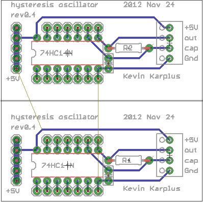
Hysteresis board
Now that we’re using a 74HC14 Schmitt trigger in the capacitive touch sensor for the hysteresis oscillator, that lab can be the first soldering project, in addition to learning about hysteresis.
I tried laying out a very compact PC board for the students to solder (still requiring them to do some design—they’ll have to breadboard their design first to get appropriate R and C values). I came up with one very compact design that could get 4 copies into the 50mm×50mm limit of the $1 boards from ITEAD, making the boards only 25¢ each.

Compact layout to get 4 hysteresis oscillator boards out of one 50mm×50mm board. The gutters are pretty narrow, though, and I’m not sure I’m skillful enough with the board shears to cut that accurately. The yellow “airwires” are Eagle telling me that the Gnd and +5V wires are not connected between the different copies.
It seemed a little silly to try to squeeze the price down to 25¢, when the other parts cost 90¢: 59¢ for the screw terminals, 28¢ for the Schmitt trigger chip, 1¢ for the resistor, and 2¢ for the capacitor. With this layout it is also a little tricky for the students to properly wire the unused inputs high.
Given the high risk of ruining the boards trying to cute them with the board shears, I decided to redesign for a 50¢ board.

Much looser layout, having only two copies on the 50mm x 50mm board. This version makes it easier for the students to see how things are connected, and has lots of room for the board shears to make the cut.
The lab would now require that the students measure the thresholds of the Schmitt trigger, breadboard the hysteresis oscillator, make a touch pad out of foil and packing tape, measure the frequency of the oscillation to estimate the touch pad capacitance, adjust the parameters of the Arduino program to match the frequencies of their oscillator, solder up the board, and demonstrate it working to control an LED. I think that is plenty for a 3-hour lab.
When I set up the web pages for the course, I’ll try to make sure I put the Eagle design files (.brd and .sch) for each board the students use on the web, so that future instructors can easily order more copies of the board, even if my laptop gets run over by a beer truck. That will also make it easier for instructors at other schools to try to duplicate the course.
Filed under: Circuits course, Printed Circuit Boards Tagged: Arduino, bioengineering, capacitive touch sensor, circuits, course design, Printed circuit board, Schmitt trigger, sensors, teaching


