Posts with «underwater rov» label

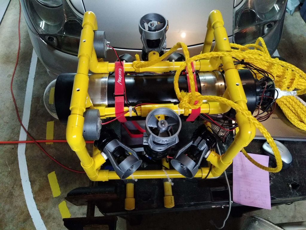
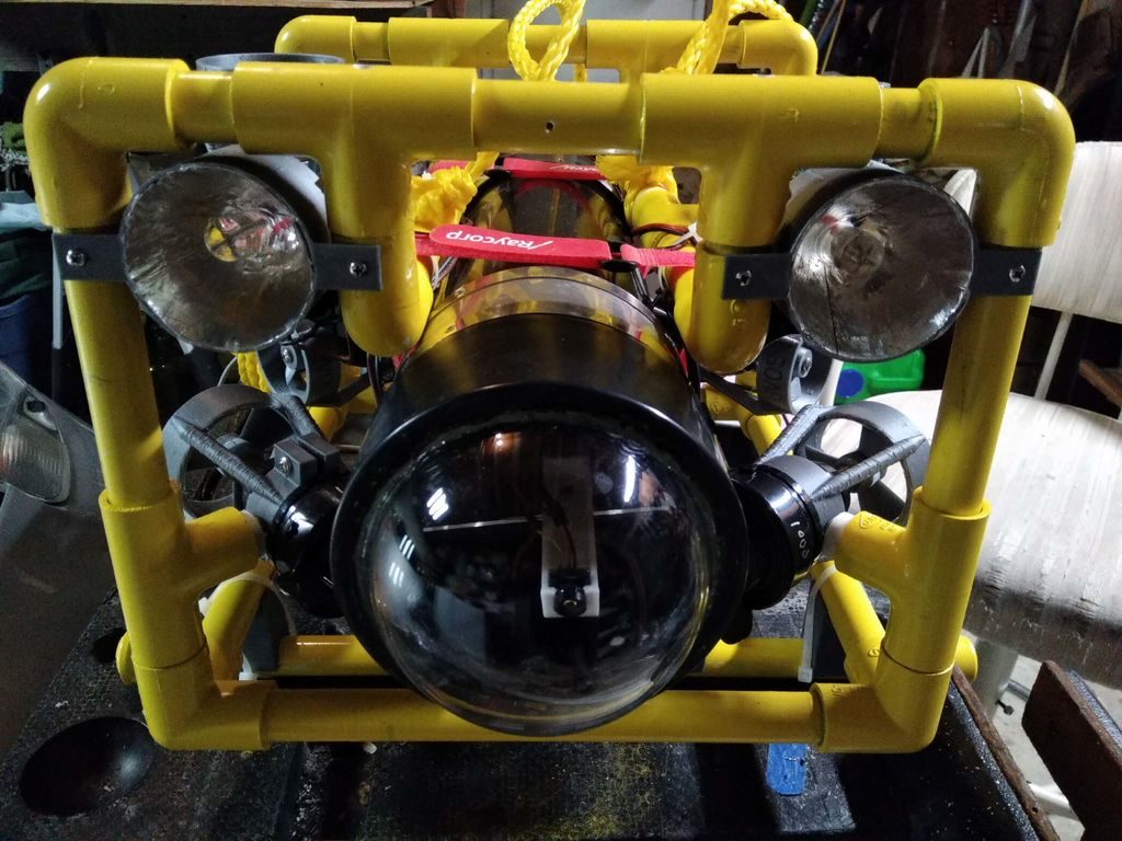
DIY submersible ROV flies through the water

If you’d like to check out your pool or a lake without getting wet, this underwater ROV looks like a great solution. 

The DIY device features a sturdy PVC frame with six thrusters that allow it to move through water like a drone through the air (complete with depth and heading hold), and uses the same kind of controller configuration as its airborne cousin.

Onboard control is handled by an Arduino Mega along with an FPV camera, which transmit signals back to a base station via an Ethernet cable stuffed inside of a length of polypropylene rope. The driver can then see what the ROV sees on a small display, supplemented with data from the base station’s Arduino Uno and an onscreen display (OSD) shield.

Arduino Blog 31 May 15:07

Sensor board for underwater ROV

Since I had bought the robotics club an I2C accelerometer and magnetometer, I decided to make a new PC board for them to mount the accelerometer, the magnetometer, and the pressure gauge on the same board.  I don’t have the SMD soldering skills to solder all the chips onto one board, and I already had breakout boards for the accelerometer and magnetometer from Sparkfun, so I decided just to put connectors for those breakout boards onto the back of the pressure sensor board.  (The back, because the pressure sensor on the front has to be stuck through a hole in the dry box and glued in place.

The new boards are tiny (1.05″ × 1.425″), so I decided to try BatchPCB (which has pricing by the square inch) rather than 4pcb.com (which has fixed pricing per board, up to a fairly large size).  The price from BatchPCB was $10 per order plus $2.50/square inch plus $0.90 for shipping, so ordering 3 copies of the board (though I only needed one), cost me $22.12, substantially less than a single board from 4pcb.com, which is $33 plus $17.30 shipping and handling per board (plus an extra $50 if your board has multiple boards on it).  The 4pcb price is lower if your board is bigger than about 15.76 square inches, so even my HexMotor boards (at 12.44 square inches) would be cheaper from BatchPCB.  If you get multiple boards from 4pcb.com on a single panel and cut them apart yourself, the breakeven point is about 35.76 square inches for a single design (so three HexMotor boards from a single 4pcb.com panel is cheaper than from BatchPCB). For multiple designs on a single panel, the 4pcb.com deal is better: for 3 different designs, a total of 27.04 square inches would make 4pcb.com the cheaper way to go.

If you want a copy of the board, you can order it from BatchPCB, or pick up the Eagle files from my web site and order copies from elsewhere.  I’ve put the HexMotor Eagle files on line also, but not put them on the BatchPCB site.  I should probably upload them there sometime.

Bottom line: BatchPCB is better for small numbers of tiny boards, but 4pcb.com is better for larger boards and multiple designs.

The BatchPCB orders came back quite quickly (12 days from order to delivery by mail), though I had been worried because their design-rule check, which they say takes minutes had taken about 8 hours.  The problem was that each check takes a few minutes, but they had hundreds in the queue over the weekend, and it took a full day to clear the queue.

I had less trouble soldering the pressure gauge this time (this was my second attempt at soldering surface mount devices).  You can see in the pictures above that the results are much cleaner than in my first attempt.

The robotics club has tested the pressure sensor on the new board (using their own code on the Arduino) and it seems to work ok,  have drilled the hole in the dry box for the port, and glued the sensor board in place using superglue.  It seems to be waterproof (at least down to 1 foot—we’ve not tested in deep water yet).

Related articles

Tagged: accelerometer, Arduino, BatchPCB, magnetometer, pressure sensor, Printed circuit board, ROV, SparkFun Electronics

Underwater ROV again this year

Last year I blogged about MATE ‘s Monterey Bay Regional underwater ROV competition in Underwater ROV contest.  I coached a robotics club at my son’s high school, and they built a small vehicle which they barely got into the water the day before the contest, because we started so late.

Although my son is being home-schooled this year, we have kept the team going, losing one member and picking up another (so we still have only 3).  The robotics club is no longer affiliated with a school, but that makes no difference, as all the school provided us was an inconvenient time to meet (lunch on Tuesdays) and 15 minutes in the pool once.  We meet for 3 hours on Sundays at my house, which gives them enough time to get something done.

I’m still paying the expenses out of my own pocket, and we now have the construction of the vehicle taking up about a third of our living room (the benchtop drill press is the first thing you see on entering the house, unless it is on the floor to make room on the robotics table for the scroll saw).

The students have made considerable progress since last year, having replaced the high-resistance tether and switch box with a low-resistance power wire and a dry box that will house an Arduino microprocessor with H-bridge chips.  They’ve made the tether with a waterproof disconnect and have tested everything for water tightness (though only at bathtub depth, not 10 feet deep).  I think that they’ll have the basic vehicle and electronics finished by the end of January, leaving some time for designing and building mission-specific tools, programming the Arduino and the laptop GUI, and learning to pilot the vehicle.  Now we just have to find a pool to practice in.

The club members have gotten much more independent this year, so my coaching involves my making some suggestions about what they should work on at the beginning of the meeting, checking to see how they are doing about once an hour, and having a discussion with them about what they’ll need to design or build next over snacks near the end of the meeting.  I also try to get them to give me specific parts to buy, but I usually end up having to find and select parts for them.  If the group were bigger (and my wallet more able to tolerate mistakes), I could have the students doing more of the purchasing.

The challenges for this year have been published, and they are in the usual verbose style.  I may have a hard time getting all the students to read the specs carefully, since the specs go on and on with irrelevant “color” hiding the nuggets of critical information.  I’m not looking forward to making the items needed for practicing the missions this year, since they are described in the same wordy way as last year (which I found difficult to follow in several places), and they haven’t even released photos or drawings of what the objects are supposed to look like.  Trying to re-create the objects from the turgid assembly directions without pictures is going to be a nightmare.

The contest does not have any tasks this year that need a depth gauge (but I bought a pressure sensor, so the students will measure depth!), but they will need to determine compass headings, so we’re trying to decide whether to get a cheap compass and put it in the camera view, or add an electronic compass module to the electronics in the dry box.  An electronic compass is definitely cooler, but we may be running out of pins on the Arduino.

Related Articles

Tagged: Arduino, contests, electronic compass, H-bridge, remotely operated underwater vehicle, robotics, ROV

HexMotor 2.3 and pressure-sensor boards

Top view of my second PC board. 3 copies of HexMotor 2.3 and 2 copies each of 3 different breakout boards for a pressure sensor.

I got the boards back from 4pcb.com about a week ago.

The HexMotor rev2.3 boards have several new features: LEDs for +5v and +6.25v, a reset button, 16-bit shift register instead of 8-bit, servo outputs connected to pins 13, 7, 2, 9, 10 (rather than to the pins used for PWM).  The new board should be able to do either 6 PWM motors or 4 PWM motors, 5 servos, and 2 non-modulated reversible motors.  I was going to have the robotics club solder the board today, but they did not have time.

[Note: as of 1March 2012, I have put the HexMotor Eagle design files on the web.]

I made some breakout boards for the MPXHZ6250A pressure sensors from Freescale Semiconductor,  which gave me my first taste of SMD soldering.  At least the design uses gull-wing pins, which can be hand soldered.  The breakout board that I think that the robotics club will end up using puts a pressure sensor on one side and headers for a piggyback ADXL335 breakout board on the back.  that way there only need to be one set of wires for connecting the analog inputs and power to the sensors.

That is the board I soldered a sensor to.

Top view of the breakout board with the sensor and headers soldered in place.

The pressure sensors are tiny! I found it fairly difficult to solder the  sensor to the boards, even holding it with clamping tweezers. I did eventually get everything to stick with no shorts between the 3 signal wires, but I did have some trouble with the unused copper pads delaminating from the board.  For future reference: all pads should have wires going to them (even the unused pads) to have enough surface area for good adherence and so that some of the pad is tucked under the solder mask.

Here are the solder connections on the side where none of the pins are used.

Here are the solder connections for the power and signal pins (and an SMD capacitor).

Despite the rather sloppy soldering, the pressure sensor does work.  It turns out that the port size is just the right size for Lego pneumatics components, so testing was pretty easy.

Sensor attached to Lego pump and gauge for testing.

Here are the results of calibration tests with the (probably not very accurate) Lego gauge, done by my son and me.

Pressure (psi) Arduino analogRead
0 367
5 518
6 542
7 576
8 599
9 632
10 657
11 683
12 710
13 734
14 775
15 801
16 832
17 861
18 887
19 915
20 941
21 967
22 1000

The range is about right, since 22 psi plus one atmosphere is about 250kPa, which is supposed to be the high end of the sensor’s range. Also, 600″ (50′) of water is 21.67 psi, so the range from 367 to 1000 corresponds to about 50′, so the sensor should give the robotics team a resolution of about 1″ for measuring depth, as expected from the spec sheet.

The data are well fit by The club members will have to recalibrate the pressure sensor in water, to get calibration as depth in cm. They’ll probably have to re-zero the sensor every day they use it, to compensate for atmospheric pressure, since it is an absolute pressure gauge.


Tagged: Arduino, Lego pneumatics, pressure sensor, Printed circuit board, SMD soldering

New board designed

I’ve just sent a new set of boards for fab.  The HexMotor rev2.3 boards have several new features: LEDs for +5v and +6.25v, a reset button, 16-bit shift register instead of 8-bit, servo outputs connected to pins 13, 7, 2, 9, 10 (rather than to the pins used for PWM).  The new board should be able to do either 6 PWM motors or 4 PWM motors, 5 servos, and 2 non-modulated reversible motors.

I’m also making some breakout boards for the MPXHZ6250A pressure sensors from Freescale Semiconductor, which will require doing some SMD soldering.  At least the design uses gull-wing pins, which can (supposedly) be hand soldered.  One of the breakout boards also has a place for mounting an ADXL335 accelerometer, which may be more difficult to solder.  I don’t think I want to spend the money for a hot-air rework station, and I’m a bit dubious about my ability to solder using a toaster oven.

The pressure sensors are tiny!  My original suggestion to the robotics club was to drill a hole in the dry box and superglue the pressure sensor to the inside of the box (after the pressure sensor had been attached to the breakout board, of course).  Now I’m not so sure that there will be enough glue area to hold firmly enough.  Perhaps a dab of some sealant on the outside of the box might help, if we can keep from plugging the hole in the sensor.

The breakout board that I think that the robotics club will end up using puts a pressure sensor on one side and headers for a piggyback ADXL335 breakout board on the back.  that way there only need to be one set of wires for connecting the analog inputs and power to the sensors.

One limitation of the Arduino for use with this combination of sensors is that the accelerometer is a 3v part and the pressure sensor is a 5v part. We’ll have to set up the analog-to-digital converter on the Arduino to have a 5v range, which reduces the precision of the acceleration readings.

I’ve also bought some other sensors (not for the underwater vehicle, but for physics class and dry robotics): a couple of ultrasonic rangefinders.  More on those in a separate post, after I’ve had a chance to play with them.


Tagged: accelerometer, Arduino, H-bridge, motor controller, pressure sensor, Printed circuit board