Posts with «serial» label

A Handy Tester for a Mountain of PS/2 Keybords

The hacking life is not without its challenges, and chief among these is the tendency to always be in acquisition mode. When we come across a great deal on bulk equipment, or see a chance to rescue some obscure gear from the e-waste stream, we generally pounce on it, regardless of the advisability.

We imagine this is why [Nathan] ended up with a hoard of PS/2 keyboards. Seriously, there are like thousands of the things. And rather than lug a computer to them for testing, [Nathan] put together this handy Arduino-based portable tester to see which keyboards still have some life left in them. The video below goes into detail on the build, but the basics are pretty simple — an Arduino, a 16×2 LCD display, and a few bits and bobs to run it off a LiPo pack and charge it up. Plus, of course, a PS/2 jack to plug in a keyboard and power it up. Interestingly, the 16×2 display is an old Parallax unit, from the days when RadioShack still existed and sold their stuff. That required a little effort to get it working with the Arduino, but in the end it works like a charm — plug in a keyboard and whatever you type shows up on the screen.

Of course, it’s hard to look at something like this, and that mountain of keyboards in the background, and not scheme up ways to really automate the whole test process. Perhaps an old 3D printer with a stylus mounted where the hot end would go could press each key in turn while the tester output is recorded — something like this Wordle-bot, but on a keyboard scale. That kind of goes against [Nathan]’s portability goal, but it’s still fun to think about.

Hack a Day 12 Jul 16:30
2  arduino  arduino hacks  keyboard  ps  serial  test  tool hacks  

KVM Uses Many Arduinos

The Arduino platform is one of the most versatile microcontroller boards available, coming in a wide variety of shapes and sizes perfect for everything from blinking a few LEDs to robotics to entire home automation systems. One of its more subtle features is the ability to use its serial libraries to handle keyboard and mouse duties. While this can be used for basic HID implementations, [Nathalis] takes it a step further by using a series of Arduinos as a KVM switch; although admittedly without the video and mouse functionality yet.

To start, an Arduino Uno accepts inputs from a keyboard which handles the incoming serial signals from the keyboard. From there, two Arduino Pro Micros are attached in parallel and receive signals from the Uno to send to their respective computers. The scroll lock key, which doesn’t do much of anything in modern times except upset Excel spreadsheeting, is the toggle switch between the two outputs. Everything is standard USB HID, so it should be compatible with pretty much everything out there. All of the source code and schematics are available in the project’s repository for anyone who wants to play along at home.

Using an Arduino to emulate a USB input device doesn’t have to be all work and no play, the same basic concept can also be used to build custom gaming controllers.

2D-Scanner Records Surfboard Profiles for Posterity

[Ryan Schenk] had a problem: he built the perfect surfboard. Normally that wouldn’t present a problem, but in this case, it did because [Ryan] had no idea how he carved the gentle curves on the bottom of the board. So he built this homebrew 2D-scanner to make the job of replicating his hand-carved board a bit easier.

Dubbed the Scanbot 69420 – interpretation of the number is left as an exercise for the reader, my dude – the scanner is pretty simple. It’s just an old mouse carrying a digital dial indicator from Harbor Freight. The mouse was gutted, with even the original ball replaced by an RC plane wheel. The optical encoder and buttons were hooked to an Arduino, as was the serial output of the dial indicator. The Arduino consolidates the data from both sensors and sends a stream of X- and Z-axis coordinates up the USB cable as the rig slides across the board on a straightedge. On the PC side, a Node.js program turns the raw data into a vector drawing that represents the profile of the board at that point. Curves are captured at various points along the length of the board, resulting in a series of curves that can be used to replicate the board.

Yes, this could have been done with a straightedge, a ruler, and a pencil and paper – or perhaps with a hacked set of calipers – but that wouldn’t be nearly as much fun. And we can certainly see applications for this far beyond the surfboard shop.

Custom Jig Makes Short Work of Product Testing

When you build one-off projects for yourself, if it doesn’t work right the first time, it’s a nuisance. You go back to the bench, rework it, and move on with life. The equation changes considerably when you’re building things to sell to someone. Once you take money for your thing, you have to support it, and anything that goes out the door busted is money out of your pocket.

[Brian Lough] ran into this fact of life recently when the widget he sells on Tindie became popular enough that he landed an order for 100 units. Not willing to cut corners on testing but also not interested in spending days on the task, he built this automated test jig to handle the job for him. The widget in question is the “Power BLough-R”, a USB pass-through device that strips the 5-volt from the line while letting the data come through; it’s useful for preventing 3D-printers from being backfed when connected to Octoprint. The tester is very much a tactical build, with a Nano in a breakout board wired to a couple of USB connectors. When the widget is connected to the tester, a complete series of checks make sure that there are no wiring errors, and the results are logged to the serial console. [Brian] now has complete confidence that each unit works before going out the door, and what’s more, the tester shaved almost a minute off each manual test. Check in out in action in the video below.

We’ve featured quite a few of [Brian]’s projects before. You may remember his Tetris-themed YouTube subscriber counter, or his seven-segment shoelace display.

[via r/Arduino]

Hack a Day 02 Feb 09:00

Arduino and Pi Share Boardspace

A Raspberry Pi Zero (W) and Arduino are very different animals, the prior has processing power and connectivity while the latter has some analog to digital converters (ADCs) and nearly real-time reactions. You can connect them to one another with a USB cable and for many projects that will happily wed the two. Beyond that, we can interface this odd couple entirely through serial, SPI, I2C, and logic-level signaling. How? Through a device by [cburgess] that is being called an Arduino shield that supports a Pi0 (W). Maybe it is a cape which interfaces with Arduino. The distinction may be moot since each board has a familiar footprint and both of them are found here.

Depending on how they are set up and programmed, one can take control over the other, or they could happily do their own thing and just exchange a little information. This board is like a marriage counselor between a Raspberry Pi and an Arduino. It provides the level-shifting so they don’t blow each other up and libraries so they can speak nicely to one another. If you want to dig a bit deeper into this one, design files and code examples are on available.

Perhaps we’ll report on this board at the heart of a pinball machine retrofit, a vintage vending machine restoration, or maybe a working prop replica from the retro bar in Back to the Future II.

Arduino Gets a Command Line Interface

When using an Arduino, at least once you’ve made it past blinking LEDs, you might start making use of the serial connection to send and receive information from the microcontroller. Communicating with the board while it’s interacting with its environment is a crucial way to get information in real-time. Usually, that’s as far as it goes, but [Pieter] wanted to take it a step farther than that with his command line interpreter (CLI) for the Arduino.

The CLI allows the user to run Unix-like commands directly on the Arduino. This means control of GPIO and the rest of the features of the microcontroller via command line. The CLI communicates between the microcontroller and the ANSI/VT100 terminal emulator of your choosing on your computer, enabling a wealth of new methods of interacting with an Arduino.

The CLI requires a hex file to be loaded onto the Arduino that you can find at a separate site, also maintained by [Pieter]. Once that’s running, you can get all of that sweet command line goodness out of your Arduino. [Pieter] also has some examples on his project page, as well as the complete how-to to get this all set up and running. There’s a lot going on in the command line world, in Linux as well as windows. So there’s plenty to explore there as well.

Hack a Day 11 Nov 03:00
arduino  cli  command line  gpio  i2c  microcontrollers  serial  shell  unix  uno  

A Crash Course In Reliable Communication

It’s probably fair to say that anyone reading these words understands conceptually how physically connected devices communicate with each other. In the most basic configuration, one wire establishes a common ground as a shared reference point and then the “signal” is sent over a second wire. But what actually is a signal, how do the devices stay synchronized, and what happens when a dodgy link causes some data to go missing?

All of these questions, and more, are addressed by [Ben Eater] in his fascinating series on data transmission. He takes a very low-level approach to explaining the basics of communication, starting with the concept of non-return-to-zero encoding and working his way to a shared clock signal to make sure all of the devices in the network are in step. Most of us are familiar with the data and clock wires used in serial communications protocols like I2C, but rarely do you get to see such a clear and detailed explanation of how it all works.

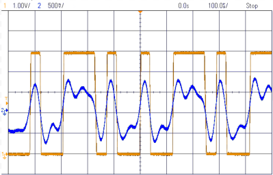
He demonstrates the challenge of getting two independent devices to communicate, trying in vain to adjust the delays on the receiving and transmitting Arduinos to try to establish a reliable link at a leisurely five bits per second. But even at this digital snail’s pace, errors pop up within a few seconds. [Ben] goes on to show that the oscillators used in consumer electronics simply aren’t consistent enough between devices to stay synchronized for more than a few hundred bits. Until atomic clocks come standard on the Arduino, it’s just not an option.

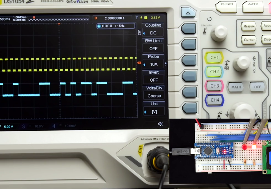
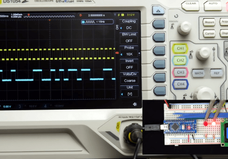
[Ben] then explains the concept of a dedicated clock signal, and how it can be used to make sure the devices are in sync even if their local clocks drift around. As he shows, as long as the data signal and the clock signal are hitting at the same time, the actual timing doesn’t matter much. Even within the confines of this basic demo, some drift in the clock signal is observed, but it has no detrimental effect on communication.

In the next part of the series, [Ben] will tackle error correction techniques. Until then, you might want to check out the fantastic piece [Elliot Williams] put together on I2C.

[Thanks to George Graves for the tip.]

Serial Connection Over Audio: Arduino Can Listen To UART

We’ve all been there: after assessing a problem and thinking about a solution, we immediately rush to pursue the first that comes to mind, only to later find that there was a vastly simpler alternative. Thankfully, developing an obscure solution, though sometimes frustrating at the time, does tend to make a good Hackaday post. This time it was [David Wehr] and AudioSerial: a simple way of outputting raw serial data over the audio port of an Android phone. Though [David] could have easily used USB OTG for this project, many microcontrollers don’t have the USB-to-TTL capabilities of his Arduino – so this wasn’t entirely in vain.

At first, it seemed like a simple task: any respectable phone’s DAC should have a sample rate of at least 44.1kHz. [David] used Oboe, a high performance C++ library for Android audio apps, to create the required waveform. The 8-bit data chunks he sent can only make up 256 unique messages, so he pre-generated them. However, the DAC tried to be clever and do some interpolation with the signal – great for audio, not so much for digital waveforms. You can see the warped signal in blue compared to what it should be in orange. To fix this, an op-amp comparator was used to clean up the signal, as well as boosting it to the required voltage.

Prefer your Arduino connections wireless? Check out this smartphone-controlled periodic table of elements, or this wireless robotic hand.

Hack a Day 31 May 09:00

Debugging with Serial Print at 5333333 Baud

Debugging with printf is something [StorePeter] has always found super handy, and as a result he’s always been interested in tweaking the process for improvements. This kind of debugging usually has microcontrollers sending messages over a serial port, but in embedded development there isn’t always a hardware UART, or it might already be in use. His preferred method of avoiding those problems is to use a USB to Serial adapter and bit-bang the serial on the microcontroller side. It was during this process that it occurred to [StorePeter] that there was a lot of streamlining he could be doing, and thanks to serial terminal programs that support arbitrary baud rates, he’s reliably sending debug messages over serial at 5.3 Mbit/sec, or 5333333 Baud. His code is available for download from his site, and works perfectly in the Arduino IDE.

The whole thing consists of some simple, easily ported code to implement a bare minimum bit-banged serial communication. This is output only, no feedback, and timing consists of just sending bits as quickly as the CPU can handle, leaving it up to the USB Serial adapter and rest of the world to handle whatever that speed turns out to be. On a 16 MHz AVR, transmitting one bit can be done in three instructions, which comes out to about 5333333 baud or roughly 5.3 Mbit/sec. Set a terminal program to 5333333 baud, and you can get a “Hello world” in about 20 microseconds compared to 1 millisecond at 115200 baud.

He’s got additional tips on using serial print debugging as a process, and he’s done a followup where he stress-tests the reliability of a 5.3 MBit/sec serial stream from an ATMega2560 at 16 MHz in his 3D printer, and found no missed packets. That certainly covers using printf as a debugger, so how about a method of using the debugger as printf?

C64 Keyboard Emulation Over Serial

There’s a lot of reasons you might want to emulate the keyboard on your Commodore 64. The ravages of time and dust may have put the original keyboard out of order, or perhaps you need to type in a long program and don’t fancy pecking away with the less-than-stellar feedback of the standard keys. [podstawek] has come up with the solution: a Commodore 64 keyboard emulator that works over serial.

It’s a simple concept, but one that works well. A Python script accepts incoming keypresses or pre-typed text, then converts them into a 6-bit binary code, which is sent to an Arduino over the serial connection. The Arduino uses the 6-bit code as addresses for an MT8808 crosspoint switch.

MT8808 Functional Diagram from Datasheet

The MT8808 is essentially an 8×8 matrix of controllable switches, which acts as the perfect tool to interface with the C64’s 8×8 keyboard matrix. Hardware wise, this behaves as if someone were actually pressing the keys on the real keyboard. It’s just replacing the original key switches with an electronic version controlled by the Arduino.

[podstawek] already has the setup working on Mac, and it should work on Linux and Windows too. There’s a little more to do yet – modifying the script to allow complex macros and to enable keys to be held – so check out the Github if you want to poke around in the source. Overall it’s a tidy, useful hack to replace the stock keyboard.

The C64 remains a popular platform for hacking — it’s even had a Twitter client since 2009.


Filed under: classic hacks, computer hacks