

USB Power Isolator Keeps Smoke In
Anyone who’s done an electronics project knows the most important part of any good design is making sure to keep the magic smoke inside of all of the components. There are a lot of ways to make sure the smoke stays in there, but one of the most important is making sure that the power supply is isolated. If you’re using a USB port on a computer as your power source, though, it can be a little more complicated to isolate it from the computer.
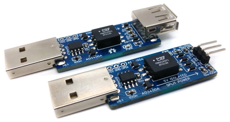
The power supply is based around a small transformer with a set of diodes to act as a rectifier. Of course, while a transformer is great at isolating power supplies, it isn’t much good at DC. That’s what the ATtiny microcontroller is for. It handles the high-speed switching of the MOSFETs, which drive the transformer and handle some power regulation. There are two different power supplies created as part of this project as well — the first generates +5V much like a normal USB plug would have, and the other creates both +5V and -5V. It will be important not to mix these two up, or that tricky blue smoke may escape.
The project page goes into extensive details on the operation of the device, so if electrical theory is of interest, this will definitely be worth a read. Isolating a valuable computer from a prototype circuit is certainly important, but if you’re looking for a way to isolate a complete USB connection, look at this build which includes isolation for a USB to FTDI adapter.

