Posts with «digit» label

Spice Up the Humble 16×2 LCD with Big Digits

The 16×2 LCD display is a classic in the microcontroller world, and for good reason. Add a couple of wires, download a library, mash out a few lines of code, and your project has a user interface. A utilitarian and somewhat boring UI, though, and one that can be hard to read at a distance. So why not spice it up with these large-type custom fonts?

As [Vaclav Krejci] explains, the trick to getting large fonts on a display that’s normally limited to two rows of 16 characters each lies in the eight custom characters the display allows to be added to its preprogrammed character set. These can store carefully crafted patterns that can then be assembled to make reasonable facsimiles of the ten numerals. Each custom pattern forms one-quarter of the finished numeral, which spans what would normally be a two-by-two character matrix on the display. Yes, there’s a one-pixel wide blank space running horizontally and vertically through each big character, but it’s not that distracting.

Composing the custom patterns, and making sure they’re usable across multiple characters, is the real hack here, and [Vaclav] put a lot of work into that. He started out in Illustrator, but quickly switched to a spreadsheet because it allowed him to easily generate the correct binary numbers to pass to the display for each pattern. It seems to have really let his creative juices flow, too — he came up with 24 different fonts! Out favorite is the one he calls “Tron,” which looks a bit like the magnetic character recognition font on the bottom of bank checks. Everyone remembers checks, right?

Hats off to [Vaclav] for a creative and fun way to spice up the humble 16×2 display. We’d love to see someone pick this up and try a complete alphanumeric character set, although that might be a tall order with only eight custom characters to work with. Then again, if Bad Apple on a 16×2 is possible…

Hack a Day 07 Apr 19:30

Kit Review – Jaycar “Short Circuits” 3 Digit Counter

Introduction

Time for another kit review and in this instalment we have a look at the “3 digit counter” kit from Jaycar. This is part of a much larger series of kits that are described in a three volume set of educational books from Jaycar titled “Short Circuits”.

Aimed at the younger readers or anyone who has an interest in learning electronics, these books (volumes one, two and three) are well written and with some study and practice the reader will make a large variety of projects and learn quite a bit. They could be considered as a worthy 21st-century replacement to the old Dick Smith “Funway…” guides.

The purpose of this kit is to give you a device which can count upwards between zero and 999 – which can be used for various purposes and also of course to learn about digital electronics.

Assembly

The kit arrives in typical retail fashion:

Everything you need to make the counter is included except for the instructions – which are found in the “Short Circuits” volume two book – and IC sockets. Kits for beginners with should come with IC sockets.

The components are separated neatly in the bag above, and it was interesting to see the use of zero ohm resistors for the two links on the board:

The PCB is excellent. The silk screening and solder-mask is very well done.

Furthermore I was really, really impressed with the level of detail with the drilling. The designer has allowed for components with different pin spacing – for example the 100 nF capacitor and transistors as shown below:

The instructions in the book are very clear and are written in an approachable fashion:

There’s also a detailed explanation on how the circuit works, some interesting BCD to decimal notes, examples of use (slot cars!) and a neat diagram showing how to mount the kit in a box using various parts from Jaycar – so you’re not left on your own.

Construction went well, starting with the low-profile parts:

… then the semiconductors:

… then the higher-profile parts and we’re finished:

There wasn’t any difficulty at all, and the counter worked first time. Although I’m not a new user, the quality of PCB and instructions would have been a contributing factor to the success of the kit.

How it works

The input signal for the counter (in this case a button controlling current from the supply rail) is “squared-up” by an MC14093 schmitt-trigger IC, which then feeds a MC14553 BCD counter IC, which counts and then feeds the results to a 4511 BCD to 7-segment converter to drive the LED digits which are multiplexed by the MC14553. For the schematic and details please refer to the book. Operation is simple, and demonstrated in the following video:

However you can feed the counter an external signal, by simply applying it to the input section of the circuit. After a quick modification:

… it was ready to be connected to a function generator. In the following video we send pulses with a varying frequency up to 2 kHz:

Conclusion

This is a neat kit, works well and with the accompanying book makes a good explanation of a popular digital electronics subject. There aren’t many good “electronics for beginners” books on the market any more, howevert the “Short Circuits” range from Jaycar really fit the bill.

So if you’re looking to learn more about electronics or start someone else off, head in to Jaycar and have a look. Readers from outside Australia are also covered. Full-sized images are available on flickr.

And while you’re here – are you interested in Arduino? Check out my new book “Arduino Workshop” from No Starch Press.

In the meanwhile have fun and keep checking into tronixstuff.com. Why not follow things on twitterGoogle+, subscribe  for email updates or RSS using the links on the right-hand column? And join our friendly Google Group – dedicated to the projects and related items on this website. Sign up – it’s free, helpful to each other –  and we can all learn something.

[Note – kit and book purchased without notifying the supplier]

The post Kit Review – Jaycar “Short Circuits” 3 Digit Counter appeared first on tronixstuff.

Tronixstuff 04 Dec 22:00

Kit Review – Altronics 3 Digit Counter Module

Introduction

In this review we examine the three digit counter module kit from Altronics. The purpose of this kit is to allow you to … count things. You feed it a pulse, which it counts on the rising edge of the signal. You can have it count up or down, and each kit includes three digits.

You can add more digits, in groups of three with a maximum of thirty digits. Plus it’s based on simple digital electronics (no microcontrollers here) so there’s some learning afoot as well. Designed by Graham Cattley the kit was first described in the now-defunct (thanks Graham) January 1998 issue of Electronics Australia magazine.

Assembly

The kit arrives in the typical retail fashion:

And includes the magazine article reprint along with Altronics’ “electronics reference sheet” which covers many useful topics such as resistor colour codes, various formulae, PCB track widths, pinouts and more. There is also a small addendum which uses two extra (and included) diodes for input protection on the clock signal:

The counter is ideally designed to be mounted inside an enclosure of your own choosing, so everything required to build a working counter is included however that’s it:

No IC sockets, however I decided to live dangerously and not use them – the ICs are common and easily found. The PCBs have a good solder mask and silk screen:

With four PCBs (one each for a digit control and one for the displays) the best way to start was to get the common parts out of the way and fitted, such as the current-limiting resistors, links, ICs, capacitors and the display module. The supplied current-limiting resistors are for use with a 9V DC supply, however details for other values are provided in the instructions:

At this point you put one of the control boards aside, and then start fitting the other two to the display board. This involves holding the two at ninety degrees then soldering the PCB pads to the SIL pins on the back of the display board. Starting with the control board for the hundreds digit first:

… at this stage you can power the board for a quick test:

… then fit the other control board for the tens digit and repeat:

Now it’s time to work with the third control board. This one looks after the one’s column and also a few features of the board. Several functions such as display blanking, latch (freeze the display while still counting) and gate (start or stop counting) can be controlled and require resistors fitted to this board which are detailed in the instructions.

Finally, several lengths of wire (included) are soldered to this board so that they can run through the other two to carry signals such as 5V, GND, latch, reset, gate and so on:

These wires can then be pulled through and soldered to the matching pads once the last board has been soldered to the display board:

 You also need to run separate wires between the carry-out and clock-in pins between the digit control boards (the curved ones between the PCBs):

For real-life use you also need some robust connections for the power, clock, reset lines, etc., however for demonstration use I just used alligator clips. Once completed a quick power-up showed the LEDs all working:

How it works

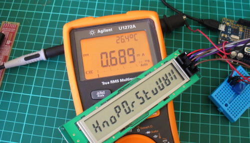
Each digit is driven by a common IC pairing – the  4029 (data sheet) is a presettable up/down counter with a BCD (binary-coded decimal) output which feeds a 4511 (data sheet) that converts the BCD signal into outputs for a 7-segment LED display. You can count at any readable speed, and I threw a 2 kHz square-wave at the counter and it didn’t miss a beat. By default the units count upwards, however by setting one pin on the board LOW you can count downwards.

Operation

Using the counters is a simple matter of connecting power, the signal to count and deciding upon display blanking and the direction of counting. Here’s a quick video of counting up, and here it is counting back down.

Conclusion

This is a neat kit that can be used to count pulses from almost anything. Although some care needs to be taken when soldering, this isn’t anything that cannot be overcome without a little patience and diligence. So if you need to count something, get one ore more of these kits from Altronics. Full-sized images are available on flickr. And while you’re here – are you interested in Arduino? Check out my new book “Arduino Workshop” from No Starch Press – also shortly available from Altronics.

In the meanwhile have fun and keep checking into tronixstuff.com. Why not follow things on twitterGoogle+, subscribe  for email updates or RSS using the links on the right-hand column? And join our friendly Google Group – dedicated to the projects and related items on this website. Sign up – it’s free, helpful to each other –  and we can all learn something.

The post Kit Review – Altronics 3 Digit Counter Module appeared first on tronixstuff.

Tronixstuff 18 Nov 06:55

Arduino and KTM-S1201 LCD modules

Learn how to use very inexpensive KTM-S1201 LCD modules in this edition of our Arduino tutorials. This is chapter forty-nine of a series originally titled “Getting Started/Moving Forward with Arduino!” by John Boxall – A tutorial on the Arduino universe. The first chapter is here, the complete series is detailed here.

Introduction

After looking for some displays to use with another (!) clock, I came across some 12-digit numeric LCD displays. They aren’t anything flash, and don’t have a back light –  however they were one dollar each. How could you say no to that? So I ordered a dozen to try out. The purpose of this tutorial is to show you how they are used with an Arduino in the simplest manner possible.

Moving forward – the modules look like OEM modules for desktop office phones from the 1990s:

With a quick search on the Internet you will find a few sellers offering them for a dollar each. The modules (data sheet) use the NEC PD7225 controller IC (data sheet):

They aren’t difficult to use, so I’ll run through set up and operation with a few examples.

Hardware setup

First you’ll need to solder some sort of connection to the module – such as 2×5 header pins. This makes it easy to wire it up to a breadboard or a ribbon cable:

The rest of the circuitry is straight-forward. There are ten pins in two rows of five, and with the display horizontal and the pins on the right, they are numbered as such:

Now make the following connections:

  • LCD pin 1 to 5V
  • LCD pin 2 to GND
  • LCD pin 3 to Arduino D4
  • LCD pin 4 to Arduino D5
  • LCD pin 5 to Arduino D6
  • LCD pin 6 to Arduino D7
  • LCD pin 7 – not connected
  • LCD pin 8 – Arduino D8
  • LCD pin 9 to the centre pin of a 10k trimpot – whose other legs connect to 5V and GND. This is used to adjust the contrast of the LCD.

The Arduino digital pins that are used can be changed – they are defined in the header file (see further on). If you were curious as to how low-current these modules are:

That’s 0.689 mA- not bad at all. Great for battery-powered operations. Now that you’ve got the module wired up, let’s get going with some demonstration sketches.

Software setup

The sketches used in this tutorial are based on work by Jeff Albertson and Robert Mech, so kudos to them – however we’ve simplified them a little to make use easier. We’ll just cover the functions required to display data on the LCD. However feel free to review the sketches and files along with the controller chip datasheet as you’ll get an idea of how the controller is driven by the Arduino.

When using the LCD module you’ll need a header file in the same folder as your sketch. You can download the header file from here. Then every time you open a sketch that uses the header file, it should appear in a tab next to the main sketch, for example:

There’s also a group of functions and lines required in your sketch. We’ll run through those now – so download the first example sketch, add the header file and upload it. Your results should be the same as the video below:

So how did that work? Take a look at the sketch you uploaded.  You need all the functions between the two lines of “////////////////////////” and also the five lines in void setup(). Then you can display a string of text or numbers using

ktmWriteString();

which was used in void loop(). You can use the digits 0~9, the alphabet (well, what you can do with 7-segments), the degrees symbol (use an asterix – “*”) and a dash (use  – “-“). So if your sketch can put together the data to display in a string, then that’s taken care of.

If you want to clear the screen, use:

ktmCommand(_ClearDsp);

Next – to individually place digits on the screen, use the function:

tmPrnNumb(n,p,d,l);

Where n is the number to be displayed (zero or a positive integer), p is the position on the LCD for the number’s  (the positions from left to right are 11 to 0…), d is the number of digits to the right of the decimal point (leave as zero if you don’t want a decimal point), and l is the number of digits being displayed for n. When you display digits using this function you can use more than one function to compose the number to be displayed – as this function doesn’t clear the screen.

To help get your head around it, the following example sketch (download) has a variety of examples in void loop(). You can watch this example in the following video:

Conclusion

So there you have it – an incredibly inexpensive and possibly useful LCD module. Thank you to Jeff Albertson and Robert Mech for their help and original code.

In the meanwhile have fun and keep checking into tronixstuff.com. Why not follow things on twitterGoogle+, subscribe  for email updates or RSS using the links on the right-hand column? And join our friendly Google Group – dedicated to the projects and related items on this website. Sign up – it’s free, helpful to each other –  and we can all learn something.

The post Arduino and KTM-S1201 LCD modules appeared first on tronixstuff.