Posts with «cmos» label

Arduino Versus Logic: The Coil Gun War Continues

Looks like another shot has been fired in the simmering Coil Gun Control War. This time, [Great Scott] is taken to the discrete woodshed with a simplified and improved control circuit using a single CMOS chip and a few transistors. Where will it end? Won’t somebody think of the children?

The latest salvo is in response to [GreatScott]’s attempt to control a DIY coil gun with discrete logic, which in turn was a response to comments that he took the easy way out and used an Arduino in the original build. [Great Scott]’s second build was intended to justify the original design choice, and seemed to do a good job of explaining how much easier and better the build was with a microcontroller. Case closed, right?

Nope. Embedded designer [fede.tft] wasn’t sure the design was even close to optimized, so he got to work — on his vacation, no less!’ He trimmed the component count down to a single CMOS chip (a quad Schmitt trigger NAND), a couple of switching transistors, the MOSFETs that drive the coils, and a few passives. The NANDs are set up as flip-flops that are triggered and reset by the projectile sensors, which are implemented as hardwired AND gates. The total component count is actually less than the support components on the original Arduino build, and [fede.tft] goes so far as to offer ideas for an alternative that does away with the switching transistors.

Even though [fede.tft] admits that [GreatScott] has him beat since he actually built both his circuits, hats off to him for showing us what can likely be accomplished with just a few components. We’d like to see someone implement this design, and see just how simple it can get.


Filed under: Arduino Hacks, weapons hacks

Hacklet #8: The Animals

This week on the Hacklet we’re looking at Hackaday.io projects that are all about animals! Hackers and makers are well-known animal lovers, in fact many a hacker can be found with a pet curled up at their feet, or on their keyboard!

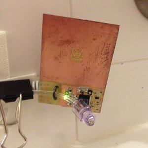
[Brian's] cat Roger loves drinking from the bathtub faucet. Unfortunately Roger hasn’t learned how to operate the faucet himself, so it gets left on quite a bit. To keep Roger happy while saving water, [Brian] created the Snooty Cat Waterer. Cat’s still don’t have thumbs, so [Brian] turned to capacitive sensing in the form of a Microchip MTCH10 capacitive proximity sensor chip. Coupled with a home etched PC board, the waterer can detect a cat at 3 inches. A valve and water feed teed off the toilet provide the flow. The project is moving along well, though Roger has been slow to warm up to this new water source.


[Jsc] has the opposite problem. His cat has decided that bathtubs are the perfect litter boxes. [Jsc] is taking aim at this little problem with his Cat Dissuader. After a servo controlled squirt bottle proved too anemic for his needs, [Jsc] turned to the Super Soaker Hydrostorm. These electric water guns can be had for as little as $16 on sale. [JSC] didn’t want to permanently modify the gun, so he 3D printed a switchable battery pack.The replacement pack is actually powered by a simple wall wart. Power to the gun is controlled by an Arduino, which senses his cat with a passive infrared sensor. Since the dissuader was installed, [Jsc's] cat has been a model citizen!


Cat’s don’t get all the love though, plenty of engineers and hackers have dogs around the house. [Colin] loves his dog, but he and his family were forgetting to feed it. He created Feed the Dog to help the household keep its four-legged member from going hungry. [Colin] tried a microcontroller, but eventually settled on implementing the circuit with old-fashioned 4000 series CMOS logic chips. He used a 4060 (14-stage ripple counter w/ internal oscillator) as an 8 hour timer, and 4013 dual flip-flop. Operation of Feed the Dog is as simple as wagging your tail. Once the dog is feed, the human presses a button. A green “Just fed” LED will glow for 30 minutes, then go dark. After about 6 hours, a red LED turns on. After 8 hours, the red LED starts blinking, letting everyone know that it’s time to feed the dog.


[Steve] has outdoor pets. Chooks to be exact, or chickens for the non Australians out there. He loves watching his birds, especially Darth Vader, who is practicing to become a rooster. To keep track of the birds, he’s created What the Chook?, a sensor suite for the hen-house. He’s using a GCDuiNode with a number of sensors. Temperature, humidity, even a methane detector for when the bedding needs to be replaced. An OV528 JPEG camera allows [Steve] to get pictures of his flock. The entire project connects via WiFi. Steve hopes to power it from a couple of AA batteries. [Steve] also entered What the Chook? in The Hackaday Prize. If he wins, this will be the first case of flightless birds sending a human to space!


Hey – Did you know that Hackaday is building a Hackerspace in Pasadena California? We’re rounding up the local community while our space is being built out. Join us at a Happy Hour Show & Tell Meetup Event hosted by our own [Jasmine Brackett] August 18th! It’s an informal show and tell, so you don’t have to bring a hack to attend. If you’re local to Pasadena, come on down and say hello!


Filed under: Hackaday Columns

Kit Review – Altronics 3 Digit Counter Module

Introduction

In this review we examine the three digit counter module kit from Altronics. The purpose of this kit is to allow you to … count things. You feed it a pulse, which it counts on the rising edge of the signal. You can have it count up or down, and each kit includes three digits.

You can add more digits, in groups of three with a maximum of thirty digits. Plus it’s based on simple digital electronics (no microcontrollers here) so there’s some learning afoot as well. Designed by Graham Cattley the kit was first described in the now-defunct (thanks Graham) January 1998 issue of Electronics Australia magazine.

Assembly

The kit arrives in the typical retail fashion:

And includes the magazine article reprint along with Altronics’ “electronics reference sheet” which covers many useful topics such as resistor colour codes, various formulae, PCB track widths, pinouts and more. There is also a small addendum which uses two extra (and included) diodes for input protection on the clock signal:

The counter is ideally designed to be mounted inside an enclosure of your own choosing, so everything required to build a working counter is included however that’s it:

No IC sockets, however I decided to live dangerously and not use them – the ICs are common and easily found. The PCBs have a good solder mask and silk screen:

With four PCBs (one each for a digit control and one for the displays) the best way to start was to get the common parts out of the way and fitted, such as the current-limiting resistors, links, ICs, capacitors and the display module. The supplied current-limiting resistors are for use with a 9V DC supply, however details for other values are provided in the instructions:

At this point you put one of the control boards aside, and then start fitting the other two to the display board. This involves holding the two at ninety degrees then soldering the PCB pads to the SIL pins on the back of the display board. Starting with the control board for the hundreds digit first:

… at this stage you can power the board for a quick test:

… then fit the other control board for the tens digit and repeat:

Now it’s time to work with the third control board. This one looks after the one’s column and also a few features of the board. Several functions such as display blanking, latch (freeze the display while still counting) and gate (start or stop counting) can be controlled and require resistors fitted to this board which are detailed in the instructions.

Finally, several lengths of wire (included) are soldered to this board so that they can run through the other two to carry signals such as 5V, GND, latch, reset, gate and so on:

These wires can then be pulled through and soldered to the matching pads once the last board has been soldered to the display board:

 You also need to run separate wires between the carry-out and clock-in pins between the digit control boards (the curved ones between the PCBs):

For real-life use you also need some robust connections for the power, clock, reset lines, etc., however for demonstration use I just used alligator clips. Once completed a quick power-up showed the LEDs all working:

How it works

Each digit is driven by a common IC pairing – the  4029 (data sheet) is a presettable up/down counter with a BCD (binary-coded decimal) output which feeds a 4511 (data sheet) that converts the BCD signal into outputs for a 7-segment LED display. You can count at any readable speed, and I threw a 2 kHz square-wave at the counter and it didn’t miss a beat. By default the units count upwards, however by setting one pin on the board LOW you can count downwards.

Operation

Using the counters is a simple matter of connecting power, the signal to count and deciding upon display blanking and the direction of counting. Here’s a quick video of counting up, and here it is counting back down.

Conclusion

This is a neat kit that can be used to count pulses from almost anything. Although some care needs to be taken when soldering, this isn’t anything that cannot be overcome without a little patience and diligence. So if you need to count something, get one ore more of these kits from Altronics. Full-sized images are available on flickr. And while you’re here – are you interested in Arduino? Check out my new book “Arduino Workshop” from No Starch Press – also shortly available from Altronics.

In the meanwhile have fun and keep checking into tronixstuff.com. Why not follow things on twitterGoogle+, subscribe  for email updates or RSS using the links on the right-hand column? And join our friendly Google Group – dedicated to the projects and related items on this website. Sign up – it’s free, helpful to each other –  and we can all learn something.

The post Kit Review – Altronics 3 Digit Counter Module appeared first on tronixstuff.

Tronixstuff 18 Nov 06:55