Posts with «counter» label

Automatic Coin Sorter Brings Order to Your Coin Jar

Few things hold as much promise as the old coin jar. Unfortunately, what’s generally promised is tedium, as one faces the prospect of manually sorting, counting, and rolling the accumulated change of cash transactions past. Unless, of course, you’ve got a fancy automatic coin sorter like this one.

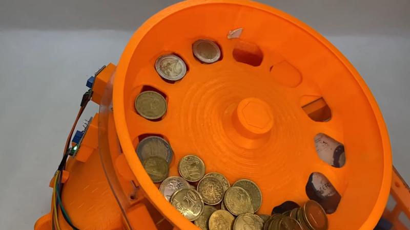
True, many banks have automatic coin sorters, but you generally have to be a paying customer to use one. And there’s always Coinstar and similar kiosks, but they always find a way to extract a fee, one way or another. [Fraens] decided not to fall for either of those traps and roll his own machine, largely from 3D-printed parts. The basic mechanism is similar to that used in commercial coin counters, with an angled bowl rotating over an array of holes sized to fit various coins. Holes in the bottom of the feed bowl accept coins fed from a hopper and transport them up to the coin holes. The smallest coins fall out of the bowl first, followed by the bigger coins; each coin drops into a separate bin after passing through an optical sensor to count the number of each on an Arduino. Subtotals and a grand total of the haul are displayed on a small LCD screen. The video below shows the build and the sorter in operation.

[Fraens] built this sorter specifically for Euro coins, but it should be easy enough to modify the sorting slots for different currencies. It’s not the first coin sorter we’ve seen, of course, and while we applaud its design simplicity and efficient operation, it can’t hold a candle to the style of this decidedly less practical approach.

Hack a Day 25 May 00:00

Homebrew ROM Reader Saves Data from a Vintage Minicomputer

Have you ever heard of a Centurion minicomputer? If not, don’t feel bad — we hadn’t either, until [David Lovett] stumbled upon a semi-complete version of the 1980-ish mini in all its wood-trimmed, dust-encased glory. And what does a hacker do with such an acquisition but attempt to get it going again?

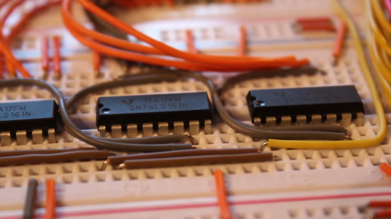
Of course, getting a machine from the Reagan administration running is not without its risks, including the chance of losing whatever is on the machine’s many ROM chips forever. When finding a commercial ROM reader supporting the various chips proved difficult, [David] decided to build his own. The work was eased considerably by the fact that he had managed to read one chip in a commercial reader, giving him a baseline to compare his circuit against. The hardware is straightforward — a 12-bit counter built from a trio of cascaded 74LS161s to step through addresses, plus an Arduino Nano to provide clock pulses and to read the data out to the serial port.

The circuit gave the same results as the known good read, meaning results would be valid for the rest of the chips. The breadboard setup made supporting multiple ROM pinouts easy, even for the chips that take -9 volts. What exactly the data on the ROMs mean, if anything, remains a mystery, but at least it’s backed up now.

Before anyone notes the obvious, yes, [David] could have used a 555 to clock the reader — perhaps even this one. We’d actually have loved that, but we get it — sometimes you just need to throw an Arduino at a job and be done with it.

Hack a Day 11 Aug 06:00

A Farewell To YouTube Sub Counters Set To Break With API Change

Of all the things you never would have guessed you’d need just ten years ago, a YouTube subscriber counter would probably rank highly. You would have guessed that the little hits of dopamine accompanying each tick upward of a number would be so addictive?

As it turns out, lots of people wanted to keep a running total of their online fans, and a bewilderingly varied ecosystem of subscriber counters has cropped up. All of them rely on the API that YouTube exposes for such purposes, which as [Brian Lough] points out is about to change and break every subscription counter ever made. In the YouTube sub counter space, [Brian] is both an enabler – he built an Arduino wrapper to fetch YT sub counts easily – and a serial builder of displays for other YouTubers. The video below shows a collection of his work, many based on RGB LED matrix display, like the one used in his Tetris-themed sub counter. They’re all well-built, nice to look at, and sadly, destined for obsolescence sometime in August when the API changes.

The details of the API changes were made public in April, and for the subs count it amounts to rounding the count and displaying large counts as, for instance, 510k as opposed to 510,023. We’re confident that [Brian] and other display builders will be able to salvage some of their counters with code changes, but others will probably require hardware changes. Thanks, YouTube.

Hack a Day 02 Aug 03:00

Many Uses For A Single Button

When building projects with a simple goal in mind, it’s not unheard of for us to add more and more switches, buttons, and complexity as the project goes through its initial prototyping stages. Feature creep like this tends to result in a tangled mess rather than a usable project. With enough focus, though, it’s possible to recognize when it’s happening and keep to the original plans. On the other hand, this single-button project with more than one use seems to be the opposite of feature creep. (YouTube, embedded below.)

[Danko]’s project has one goal: be as useful as possible while only using a single button and a tiny screen. Right now the small handheld device can be used as a stopwatch, a counter, and can even play a rudimentary version of flappy bird. It uses an Arduino Pro Mini, a 64×48 OLED screen running on I2C, and has a miniscule 100 mAh 3.7V battery to power everything. The video is worth watching if you’ve never worked with this small of a screen before, too.

Getting three functions out of a device with only one button is a pretty impressive feat, and if you can think of any other ways of getting more usefulness out of something like this be sure to leave it in the comments below. [Danko] is no stranger to simple projects with tiny screens, either. We recently featured his homebrew Arduino calculator that uses an even smaller screen.

Kit Review – Jaycar “Short Circuits” 3 Digit Counter

Introduction

Time for another kit review and in this instalment we have a look at the “3 digit counter” kit from Jaycar. This is part of a much larger series of kits that are described in a three volume set of educational books from Jaycar titled “Short Circuits”.

Aimed at the younger readers or anyone who has an interest in learning electronics, these books (volumes one, two and three) are well written and with some study and practice the reader will make a large variety of projects and learn quite a bit. They could be considered as a worthy 21st-century replacement to the old Dick Smith “Funway…” guides.

The purpose of this kit is to give you a device which can count upwards between zero and 999 – which can be used for various purposes and also of course to learn about digital electronics.

Assembly

The kit arrives in typical retail fashion:

Everything you need to make the counter is included except for the instructions – which are found in the “Short Circuits” volume two book – and IC sockets. Kits for beginners with should come with IC sockets.

The components are separated neatly in the bag above, and it was interesting to see the use of zero ohm resistors for the two links on the board:

The PCB is excellent. The silk screening and solder-mask is very well done.

Furthermore I was really, really impressed with the level of detail with the drilling. The designer has allowed for components with different pin spacing – for example the 100 nF capacitor and transistors as shown below:

The instructions in the book are very clear and are written in an approachable fashion:

There’s also a detailed explanation on how the circuit works, some interesting BCD to decimal notes, examples of use (slot cars!) and a neat diagram showing how to mount the kit in a box using various parts from Jaycar – so you’re not left on your own.

Construction went well, starting with the low-profile parts:

… then the semiconductors:

… then the higher-profile parts and we’re finished:

There wasn’t any difficulty at all, and the counter worked first time. Although I’m not a new user, the quality of PCB and instructions would have been a contributing factor to the success of the kit.

How it works

The input signal for the counter (in this case a button controlling current from the supply rail) is “squared-up” by an MC14093 schmitt-trigger IC, which then feeds a MC14553 BCD counter IC, which counts and then feeds the results to a 4511 BCD to 7-segment converter to drive the LED digits which are multiplexed by the MC14553. For the schematic and details please refer to the book. Operation is simple, and demonstrated in the following video:

However you can feed the counter an external signal, by simply applying it to the input section of the circuit. After a quick modification:

… it was ready to be connected to a function generator. In the following video we send pulses with a varying frequency up to 2 kHz:

Conclusion

This is a neat kit, works well and with the accompanying book makes a good explanation of a popular digital electronics subject. There aren’t many good “electronics for beginners” books on the market any more, howevert the “Short Circuits” range from Jaycar really fit the bill.

So if you’re looking to learn more about electronics or start someone else off, head in to Jaycar and have a look. Readers from outside Australia are also covered. Full-sized images are available on flickr.

And while you’re here – are you interested in Arduino? Check out my new book “Arduino Workshop” from No Starch Press.

In the meanwhile have fun and keep checking into tronixstuff.com. Why not follow things on twitterGoogle+, subscribe  for email updates or RSS using the links on the right-hand column? And join our friendly Google Group – dedicated to the projects and related items on this website. Sign up – it’s free, helpful to each other –  and we can all learn something.

[Note – kit and book purchased without notifying the supplier]

The post Kit Review – Jaycar “Short Circuits” 3 Digit Counter appeared first on tronixstuff.

Tronixstuff 04 Dec 22:00

Kit Review – Altronics 3 Digit Counter Module

Introduction

In this review we examine the three digit counter module kit from Altronics. The purpose of this kit is to allow you to … count things. You feed it a pulse, which it counts on the rising edge of the signal. You can have it count up or down, and each kit includes three digits.

You can add more digits, in groups of three with a maximum of thirty digits. Plus it’s based on simple digital electronics (no microcontrollers here) so there’s some learning afoot as well. Designed by Graham Cattley the kit was first described in the now-defunct (thanks Graham) January 1998 issue of Electronics Australia magazine.

Assembly

The kit arrives in the typical retail fashion:

And includes the magazine article reprint along with Altronics’ “electronics reference sheet” which covers many useful topics such as resistor colour codes, various formulae, PCB track widths, pinouts and more. There is also a small addendum which uses two extra (and included) diodes for input protection on the clock signal:

The counter is ideally designed to be mounted inside an enclosure of your own choosing, so everything required to build a working counter is included however that’s it:

No IC sockets, however I decided to live dangerously and not use them – the ICs are common and easily found. The PCBs have a good solder mask and silk screen:

With four PCBs (one each for a digit control and one for the displays) the best way to start was to get the common parts out of the way and fitted, such as the current-limiting resistors, links, ICs, capacitors and the display module. The supplied current-limiting resistors are for use with a 9V DC supply, however details for other values are provided in the instructions:

At this point you put one of the control boards aside, and then start fitting the other two to the display board. This involves holding the two at ninety degrees then soldering the PCB pads to the SIL pins on the back of the display board. Starting with the control board for the hundreds digit first:

… at this stage you can power the board for a quick test:

… then fit the other control board for the tens digit and repeat:

Now it’s time to work with the third control board. This one looks after the one’s column and also a few features of the board. Several functions such as display blanking, latch (freeze the display while still counting) and gate (start or stop counting) can be controlled and require resistors fitted to this board which are detailed in the instructions.

Finally, several lengths of wire (included) are soldered to this board so that they can run through the other two to carry signals such as 5V, GND, latch, reset, gate and so on:

These wires can then be pulled through and soldered to the matching pads once the last board has been soldered to the display board:

 You also need to run separate wires between the carry-out and clock-in pins between the digit control boards (the curved ones between the PCBs):

For real-life use you also need some robust connections for the power, clock, reset lines, etc., however for demonstration use I just used alligator clips. Once completed a quick power-up showed the LEDs all working:

How it works

Each digit is driven by a common IC pairing – the  4029 (data sheet) is a presettable up/down counter with a BCD (binary-coded decimal) output which feeds a 4511 (data sheet) that converts the BCD signal into outputs for a 7-segment LED display. You can count at any readable speed, and I threw a 2 kHz square-wave at the counter and it didn’t miss a beat. By default the units count upwards, however by setting one pin on the board LOW you can count downwards.

Operation

Using the counters is a simple matter of connecting power, the signal to count and deciding upon display blanking and the direction of counting. Here’s a quick video of counting up, and here it is counting back down.

Conclusion

This is a neat kit that can be used to count pulses from almost anything. Although some care needs to be taken when soldering, this isn’t anything that cannot be overcome without a little patience and diligence. So if you need to count something, get one ore more of these kits from Altronics. Full-sized images are available on flickr. And while you’re here – are you interested in Arduino? Check out my new book “Arduino Workshop” from No Starch Press – also shortly available from Altronics.

In the meanwhile have fun and keep checking into tronixstuff.com. Why not follow things on twitterGoogle+, subscribe  for email updates or RSS using the links on the right-hand column? And join our friendly Google Group – dedicated to the projects and related items on this website. Sign up – it’s free, helpful to each other –  and we can all learn something.

The post Kit Review – Altronics 3 Digit Counter Module appeared first on tronixstuff.

Tronixstuff 18 Nov 06:55

Australian Electronics Nostalgia – Talking Electronics Kits

Introduction

From 1981, Australian electrical engineer Colin Mitchell started publishing his home-grown electronics magazine “Talking Electronics”. His goal was to get people interested and learning about electronics, and more so with a focus on digital electronics. It was (and still is) a lofty goal – in which he succeeded. From a couple of rooms in his home the magazine flourished, and many projects described within were sold as kits. At one stage there were over 150 Talking Electronics kits on the market. You could find the books and kits in retail outlets such as Dick Smith Electronics, and for a short while there was a TE store in Moorabbin (Victoria). Colin and the team’s style of writing was easy to read and very understandable – but don’t take my word for it, you can download the magazines from his website (they’re near the bottom of the left column). Dave Jones recently interviewed Colin, and you can watch those for much more background information.

Over fifteen issues you could learn about blinking LEDs all the way to making your own expandable Z80 board computer, and some of the kits may still be available. Colin also published a series of tutorial books on electronics, and also single-magazine projects. And thus the subjects of our review … we came across the first of these single-issue projects from 1981 – the Mini Frequency Counter (then afterwards we have another kit):

How great is that? The PCB comes with the magazine. This is what set TE apart from the rest, and helped people learn by actually making it easy to build what was described in the magazine instead of just reading about it. For 1981 the PCB was quite good – they were silk-screened which was quite rare at the time:

And if you weren’t quite ready, the magazine also included details of a square-wave oscillator to make and a 52-page short course in digital electronics. However back to the kit…

Assembly

The kit uses common parts and I hoard CMOS ICs so building wasn’t a problem. This (original) version of the kit used LEDs instead of 7-segment displays (which were expensive at the time) so there was plenty of  careful soldering to do:

And after a while the counter started to come together. I used IC sockets just in case:

The rest was straight-forward, and before long 9 V was supplied, and we found success:

To be honest progress floundered for about an hour at this point – the display wouldn’t budge off zero. After checking the multi-vibrator output, calibrating the RC circuits and finally tracing out the circuit with a continuity tester, it turned out one of the links just wasn’t soldered in far enough – and the IC socket for the 4047 was broken So a new link and directly fitting the 4047 fixed it. You live and learn.

Operation

So – we now have a frequency counter that’s good for 100 Hz to the megahertz range, with a minimum of parts. Younger, non-microcontroller people may wonder how that is possible – so here’s the schematic:

The counter works by using a multi-vibrator using a CD4047 to generate a square-wave at 50, 500 and 5 kHz, and the three trimpots are adjusted to calibrate the output. The incoming pulses to measure are fed to the 4026 decade counter/divider ICs. Three of these operate in tandem and each divide the incoming count by ten – and display or reset by the alternating signal from the 4047. However for larger frequencies (above 900 Hz) you need to change the frequency fed to the display circuit in order to display the higher (left-most) digits of the result. A jumper wire is used to select the required level (however if you mounted the kit in a case, a knob or switch could be used).

For example, if you’re measuring 3.456 MHz you start with the jumper on H and the display reads 345 – then you switch to M to read 456 – then you switch to the L jumper and read 560, giving you 3456000 Hz. If desired, you can extend the kit with another PCB to create a 5-digit display. The counter won’t be winning any precision contests – however it has two purposes, which are fulfilled very well. It gives the reader an inexpensive piece of test equipment that works reasonably well, and a fully-documented project so the reader can understand how it works (and more).

And for the curious –  here it is in action:

[Update 20/07/2013] Siren Kit

Found another kit last week, the Talking Electronics “DIY Kit #31 – 9V siren”. It’s an effective and loud siren with true rise and fall, unlike other kits of the era that alternated between two fixed tones. The packaging was quite strong and idea for mail-order at the time:

The label sells the product (and shows the age):

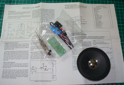
The kit included every part required to work, apart from a PP3 battery, and a single instruction sheet with a good explanation of how the circuit works, and some data about the LM358:
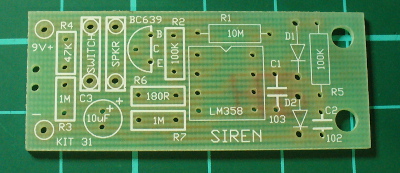
… and as usual the PCB was ahead of its’ time with full silk-screen and solder mask:
Assembly was quite straight-forward. The design is quite compact, so a lot of vertical resistor mounting was necessary due to the lack of space. However it was refreshing to not have any links to fit. After around twenty minutes of relaxed construction, it was ready to test:

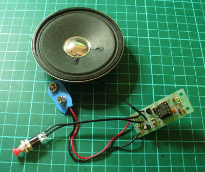
It’s a 1/2 watt speaker, however much louder than originally anticipated:

Once again, another complete and well-produced kit.

Conclusion

That was a lot of fun, and I’m off to make the matching square-wave oscillator for the frequency counter. Kudos to Colin for all those years of publication and helping people learn. Lots of companies bang on about offering tutorials and information on the Internet for free, but Colin has been doing it for over ten years. Check out his Talking Electronics website for a huge variety of knowledge, an excellent electronics course you can get on CD – and go easy on him if you have any questions.

Full-sized images available on flickr. This kit was purchased without notifying the supplier.

And if you made it this far – check out my new book “Arduino Workshop” from No Starch Press.

In the meanwhile have fun and keep checking into tronixstuff.com. Why not follow things on twitterGoogle+, subscribe  for email updates or RSS using the links on the right-hand column? And join our friendly Google Group – dedicated to the projects and related items on this website. Sign up – it’s free, helpful to each other –  and we can all learn something.

The post Australian Electronics Nostalgia – Talking Electronics Kits appeared first on tronixstuff.