Posts with «replay» label

Four Servo Fingers Play Simon Better Than You Ever Could

Remember Simon? We sure do. Simon — as in “Simon says…” — from the leading edge of electronic games in the 1970s, which used four buttons, colored lights, and simple tones as the basis for a memory game. Players had to remember the specific sequence of lights and replay the pattern in order to advance to the next round. It was surprisingly addictive, at least for the era.

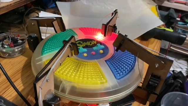
For those who never quite got into the Simon groove, fear not — the classic game has now been fully automated. While there were plenty of approaches that could have taken to interfacing to the game, [ido roseman] went with the obvious — and best, in our opinion — technique and simulated a human player’s finger presses with servo-controlled arms. Each arm carries a light-dependent resistor that registers the light coming from the key it’s poised above; the sequence of lights is sensed and recorded by an Arduino, which then drives the servo fingers’ replay attack. The fingers aren’t exactly snappy in their response, which might cause problems — if we recall correctly, Simon is somewhat picky about the speed with which the keys are pressed, at least at higher levels of play.

On the whole, we really like this one, not least for the nostalgia factor. We’ve had a lot of recreations of Simon over the years, including a Dance Dance Revolution version, but few attempts to automate it. And a crazy idea: wouldn’t it be fun to replace the replay attack with a machine learning system that figures out how to play Simon by randomly pressing keys and observing the results?

Hack a Day 11 May 00:00
arduino  cds  game  games  ldr  memory  replay  simon  

433 MHz RF module with Arduino Tutorial 4:


WARNING: Please check whether you can legally use RF transmitters and receivers at your location before attempting this project (or buying the components). This project is aimed at those who are looking to automate their home.
There are 4 parts to this tutorial:
To get the most out of this tutorial - it is best to start at tutorial Part 1, and then progress to Part 2 then Part 3 and then do Part 4 last. Doing the RF tutorials in this order will help you to understand the process better.


Project 4 : 433 Mhz RF remote replacement tutorial

Carrying on from my previous "433MHz transmitter and receiver" tutorials (1,2 & 3): I have thrown away the need to process the signal with a computer. This means that we can now get the Arduino to record the signal from an RF remote (in close proximity), and play it back in no time at all.
The Arduino will forget the signal when powered down or when the board is reset. The Arduino does not have an extensive memory - there is a limit to how many signals can be stored on the board at any one time. Some people have opted to create a "code" in their projects to help maximise the number of signals stored on the board. In the name of simplicity, I will not encode the signal like I did in my previous tutorials.
I will get the Arduino to record the signal and play it back - with the help of a button. The button will help manage the overall process, and control the flow of code.
Apart from uploading the sketch to the Arduino, this project will not require the use of a computer. Nor will it need a sound card, or any special libraries. Here are the parts required:


Parts Required:


Fritzing Sketch


Arduino Sketch


Now let's see this project in action !
Have a look at the video below to see the Arduino turning a light and fan on/off shortly after receiving the RF signal from the RF remote. The video will also show you how to put this whole project together - step by step.

The Video


This concludes my 433MHz transmitter and receiver tutorials (for now). I hope you enjoyed them.
Please let me know whether this worked for you or not.
I have not tested this project with other remotes or other frequencies - so would be interested to find out whether this technique can be used for ALL RF projects ??


If you like this page, please do me a favour and show your appreciation :

  Visit my ArduinoBasics Google + page.
Follow me on Twitter by looking for ScottC @ArduinoBasics.
Have a look at my videos on my YouTube channel.


However, if you do not have a google profile...
Feel free to share this page with your friends in any way you see fit.
ScottC 29 Jul 19:09

433 MHz RF module with Arduino Tutorial 4:

WARNING: Please check whether you can legally use RF transmitters and receivers at your location before attempting this project (or buying the components). This project is aimed at those who are looking to automate their home.

Carrying on from my previous "433MHz transmitter and receiver" tutorials (1,2 & 3): I have thrown away the need to process the signal with a computer. This means that we can now get the Arduino to record the signal from an RF remote (in close proximity), and play it back in no time at all.

The Arduino will forget the signal when powered down or when the board is reset. The Arduino does not have an extensive memory - there is a limit to how many signals can be stored on the board at any one time. Some people have opted to create a "code" in their projects to help maximise the number of signals stored on the board. In the name of simplicity, I will not encode the signal like I did in my previous tutorials.

I will get the Arduino to record the signal and play it back - with the help of a button. The button will help manage the overall process, and control the flow of code.

Apart from uploading the sketch to the Arduino, this project will not require the use of a computer. Nor will it need a sound card, or any special libraries. Here are the parts required:


Parts Required:

Fritzing Sketch


Arduino Sketch


  1
2
3
4
5
6
7
8
9
10
11
12
13
14
15
16
17
18
19
20
21
22
23
24
25
26
27
28
29
30
31
32
33
34
35
36
37
38
39
40
41
42
43
44
45
46
47
48
49
50
51
52
53
54
55
56
57
58
59
60
61
62
63
64
65
66
67
68
69
70
71
72
73
74
75
76
77
78
79
80
81
82
83
84
85
86
87
88
89
90
91
92
93
94
95
96
97
98
99
100
101
102
103
104
105
106
107
108
109
110
111
112
113
114
115
116
117
118
119
120
121
122
123
124
125
126
127


/* 
  433 MHz RF REMOTE REPLAY sketch 
     Written by ScottC 24 Jul 2014
     Arduino IDE version 1.0.5
     Website: http://arduinobasics.blogspot.com
     Receiver: XY-MK-5V      Transmitter: FS1000A/XY-FST
     Description: Use Arduino to receive and transmit RF Remote signal          
 ------------------------------------------------------------- */
 
 #define rfReceivePin A0     //RF Receiver data pin = Analog pin 0
 #define rfTransmitPin 4  //RF Transmitter pin = digital pin 4
 #define button 6           //The button attached to digital pin 6
 #define ledPin 13        //Onboard LED = digital pin 13
 
 const int dataSize = 500; //Arduino memory is limited (max=1700)
 byte storedData[dataSize]; //Create an array to store the data
 const unsigned int threshold = 100; //signal threshold value
 int maxSignalLength = 255; //Set the maximum length of the signal
 int dataCounter = 0; //Variable to measure the length of the signal
 int buttonState = 1; //Variable to control the flow of code using button presses
 int buttonVal = 0; //Variable to hold the state of the button
 int timeDelay = 105; //Used to slow down the signal transmission (can be from 75 - 135)

 void setup(){
   Serial.begin(9600); //Initialise Serial communication - only required if you plan to print to the Serial monitor
   pinMode(rfTransmitPin, OUTPUT);
   pinMode(ledPin, OUTPUT);
   pinMode(button, INPUT);
 }
 
 void loop(){
   buttonVal = digitalRead(button);
  
   if(buttonState>0 && buttonVal==HIGH){
     //Serial.println("Listening for Signal");
     initVariables();
     listenForSignal();
   }
   
   buttonVal = digitalRead(button);
   
   if(buttonState<1 && buttonVal==HIGH){
     //Serial.println("Send Signal");
     sendSignal();
   }
   
   delay(20);
 }
 
 
 /* ------------------------------------------------------------------------------
     Initialise the array used to store the signal 
    ------------------------------------------------------------------------------*/
 void initVariables(){
   for(int i=0; i<dataSize; i++){
     storedData[i]=0;
   }
   buttonState=0;
 }
 
 
 /* ------------------------------------------------------------------------------
     Listen for the signal from the RF remote. Blink the RED LED at the beginning to help visualise the process
     And also turn RED LED on when receiving the RF signal 
    ------------------------------------------------------------------------------ */
 void listenForSignal(){
   digitalWrite(ledPin, HIGH);
   delay(1000);
   digitalWrite(ledPin,LOW);
   while(analogRead(rfReceivePin)<threshold){
     //Wait here until an RF signal is received
   }
   digitalWrite(ledPin, HIGH);
   
   //Read and store the rest of the signal into the storedData array
   for(int i=0; i<dataSize; i=i+2){
     
      //Identify the length of the HIGH signal---------------HIGH
      dataCounter=0; //reset the counter
      while(analogRead(rfReceivePin)>threshold && dataCounter<maxSignalLength){
        dataCounter++;
      }  
      storedData[i]=dataCounter;    //Store the length of the HIGH signal
    
      
      //Identify the length of the LOW signal---------------LOW
      dataCounter=0;//reset the counter
      while(analogRead(rfReceivePin)<threshold && dataCounter<maxSignalLength){
        dataCounter++;
      }
      storedData[i+1]=dataCounter;  //Store the length of the LOW signal
   }
   
     storedData[0]++;  //Account for the first AnalogRead>threshold = lost while listening for signal
     digitalWrite(ledPin, LOW);
 }
 
 
 /*------------------------------------------------------------------------------
    Send the stored signal to the FAN/LIGHT's RF receiver. A time delay is required to synchronise
    the digitalWrite timeframe with the 433MHz signal requirements. This has not been tested with different
    frequencies.
    ------------------------------------------------------------------------------ */
 void sendSignal(){
   digitalWrite(ledPin, HIGH);
   for(int i=0; i<dataSize; i=i+2){
       //Send HIGH signal
       digitalWrite(rfTransmitPin, HIGH);
       delayMicroseconds(storedData[i]*timeDelay);
       //Send LOW signal
       digitalWrite(rfTransmitPin, LOW);
       delayMicroseconds(storedData[i+1]*timeDelay);
   }
   digitalWrite(ledPin, LOW);
   delay(1000);
   
   
   /*-----View Signal in Serial Monitor
   for(int i=0; i<dataSize; i=i+2){
       Serial.println("HIGH,LOW");
       Serial.print(storedData[i]);
       Serial.print(",");
       Serial.println(storedData[i+1]);
   }
   ---------------------------------- */
 }


Now let's see this project in action !

Have a look at the video below to see the Arduino turning a light and fan on/off shortly after receiving the RF signal from the RF remote. The video will also show you how to put this whole project together - step by step.

The Video


This concludes my 433MHz transmitter and receiver tutorials (for now). I hope you enjoyed them.
Please let me know whether this worked for you or not.
I have not tested this project with other remotes or other frequencies - so would be interested to find out whether this technique can be used for ALL RF projects ??

 
  Loading...


If you like this page, please do me a favour and show your appreciation :

  Visit my ArduinoBasics Google + page.
Follow me on Twitter by looking for ScottC @ArduinoBasics.
Have a look at my videos on my YouTube channel.


However, if you do not have a google profile...
Feel free to share this page with your friends in any way you see fit.

ScottC 29 Jul 19:09