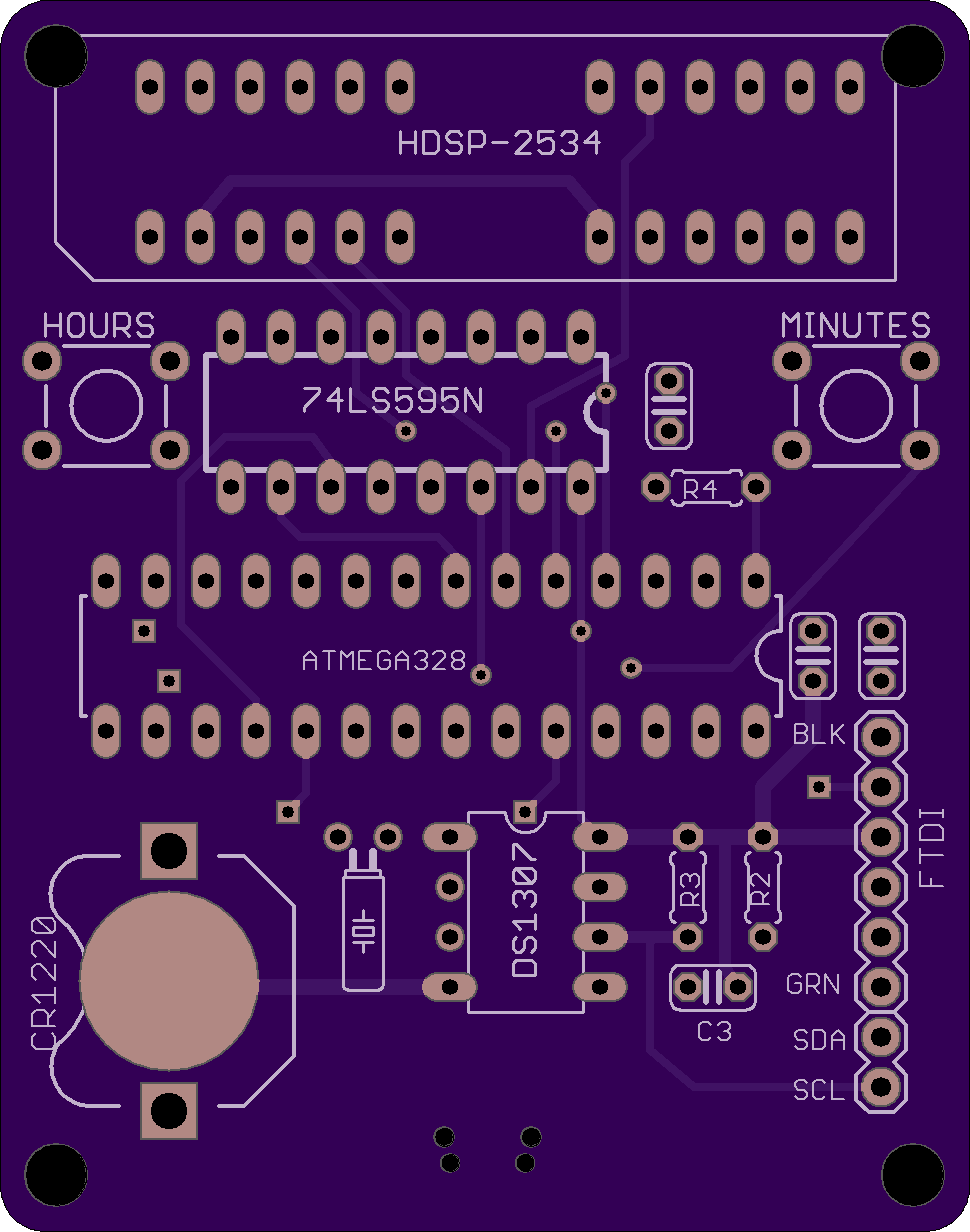
HDSP clock revision 2
The latest revision of the HDSP clock uses the same schematic, but offers an improved PCB layout, with:
This revision was successfully used as the assembly kit in the "Introduction to Practical Electronics" course for Grade 6 students.
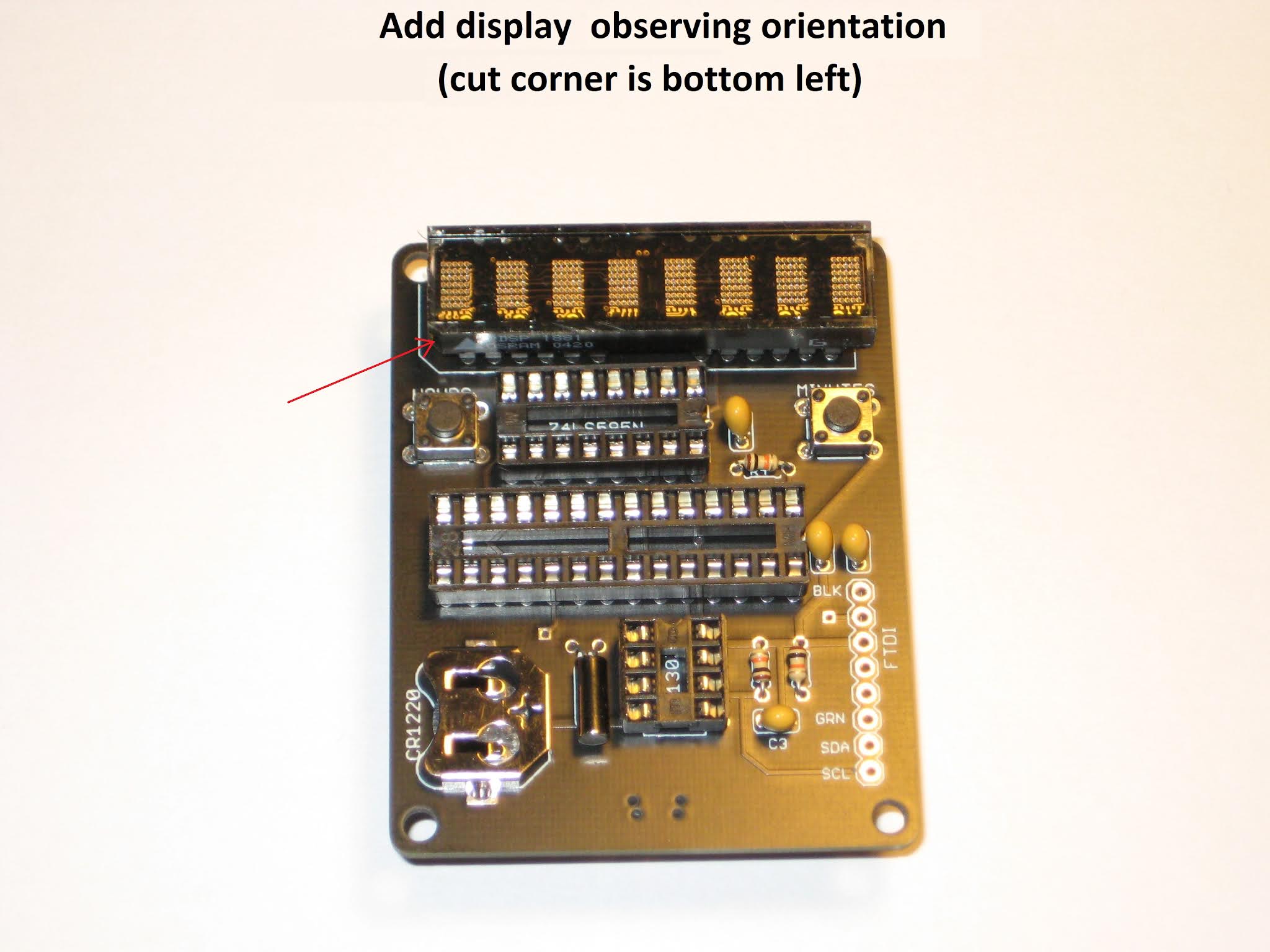
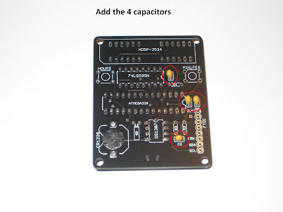
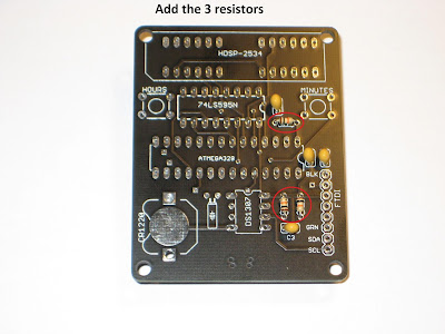
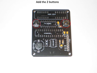
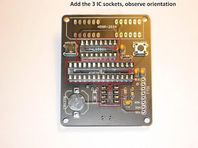
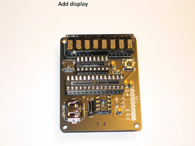
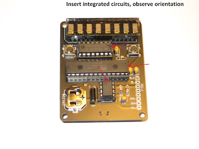
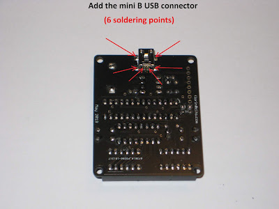
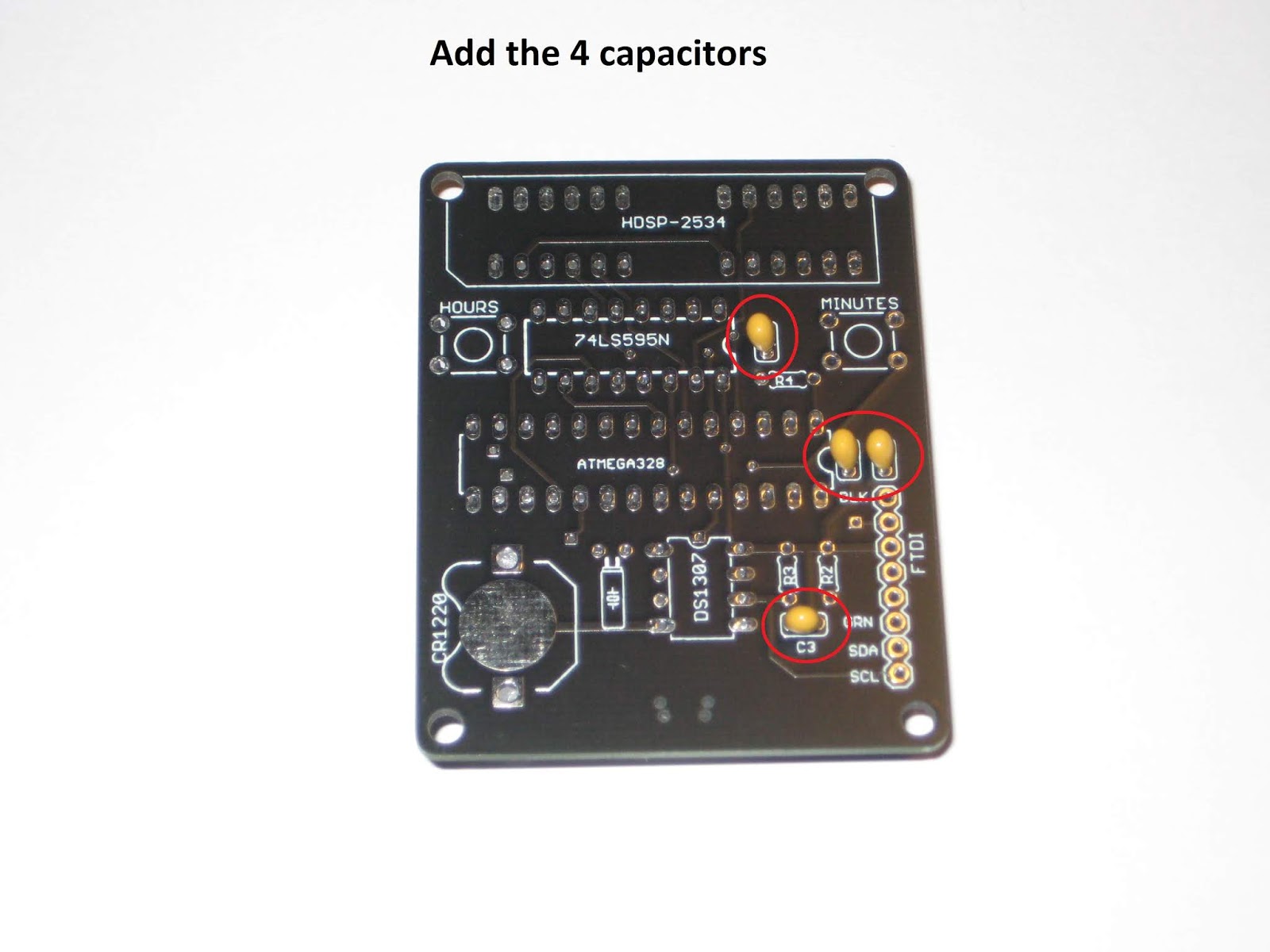
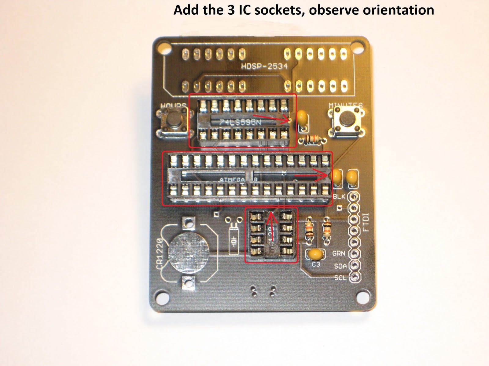
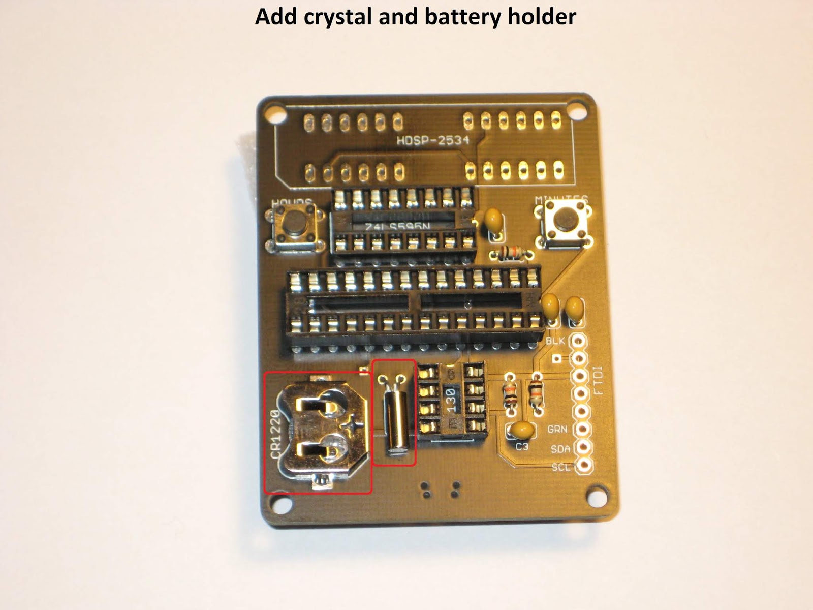
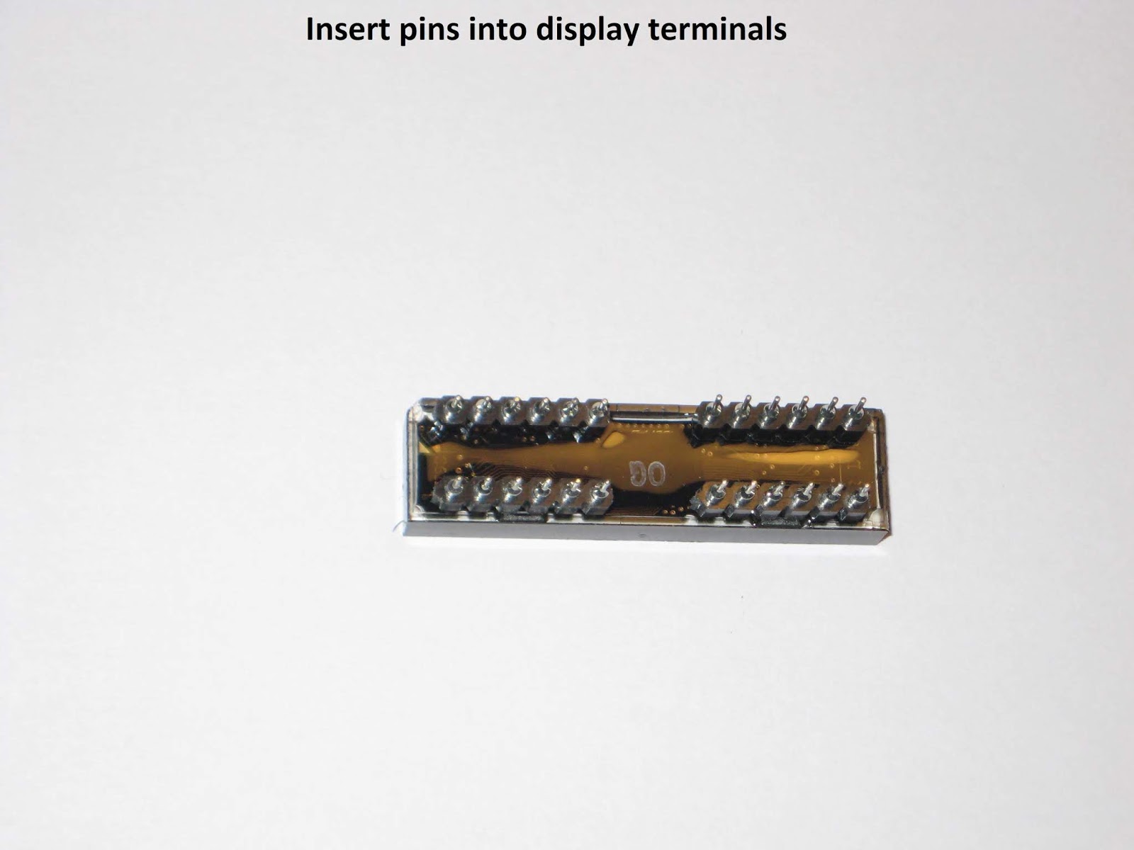
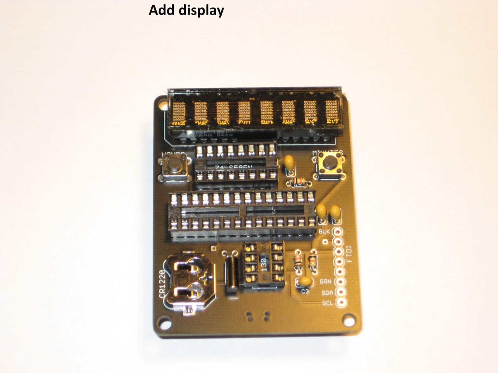
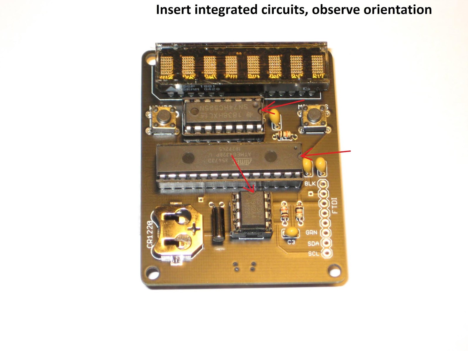
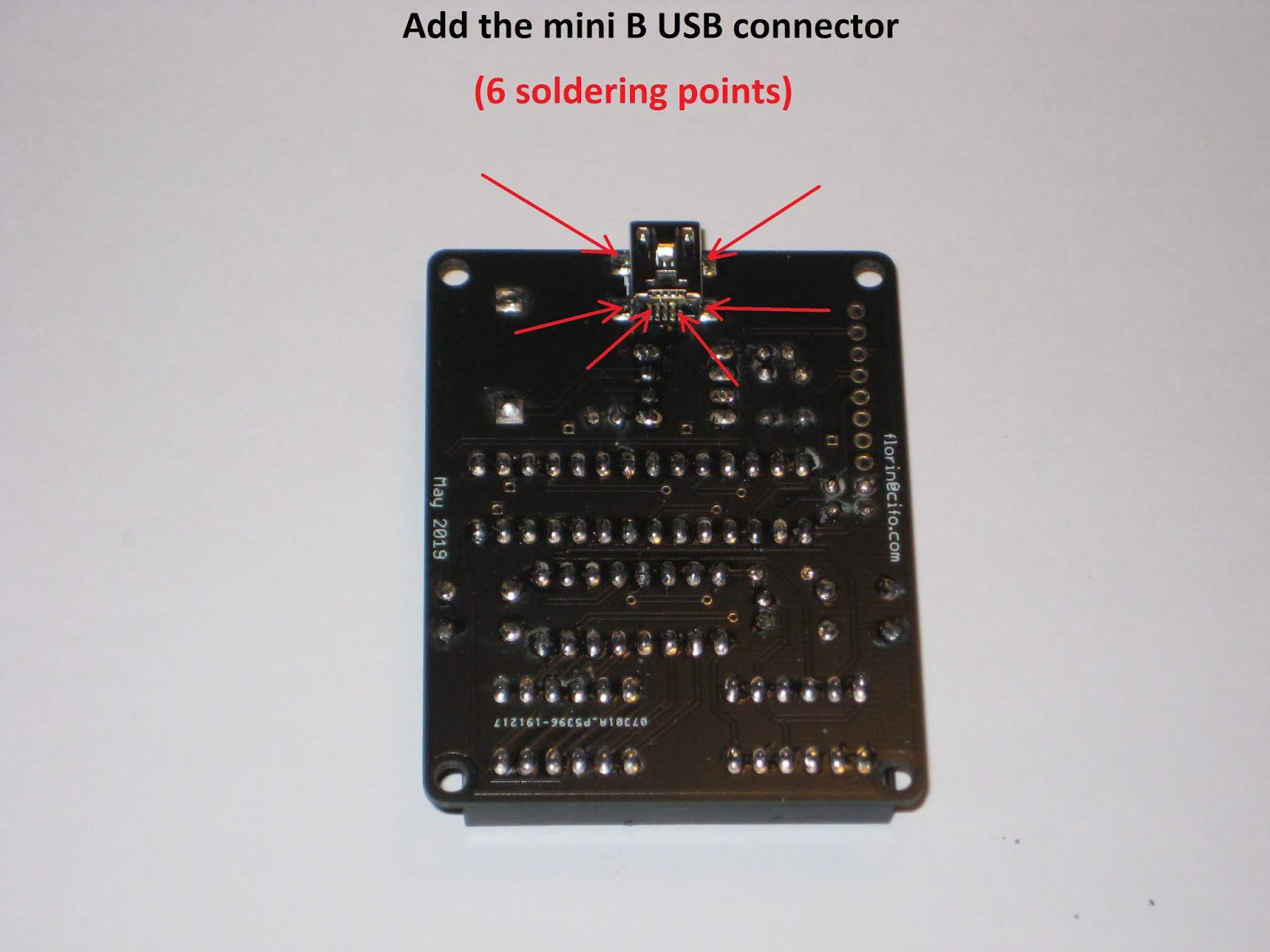
This would also be a good place for step-by-step assembly instructions, for those who require directions.


Use a mini B USB cable to power the clock. It should work right away, since the processor is already programmed with the clock software. Use the "Hours" (left) and "Minutes" (right) buttons to set up the time.
Also, insert the CR1220 battery into the holder, to make sure the DS1307 RTC (real time clock) keeps time when the clock board is not powered from USB. Note that the small coin battery ONLY powers the RTC integrated circuit, and not the whole clock. The display is lit when connected to the USB power.

- 4 holes in the corners, for encasing;
- addition of I2C signals to the FTDI connector, for expansion;
- the regular push buttons can be replaced with 2-pin right angle buttons;
This revision was successfully used as the assembly kit in the "Introduction to Practical Electronics" course for Grade 6 students.
This would also be a good place for step-by-step assembly instructions, for those who require directions.
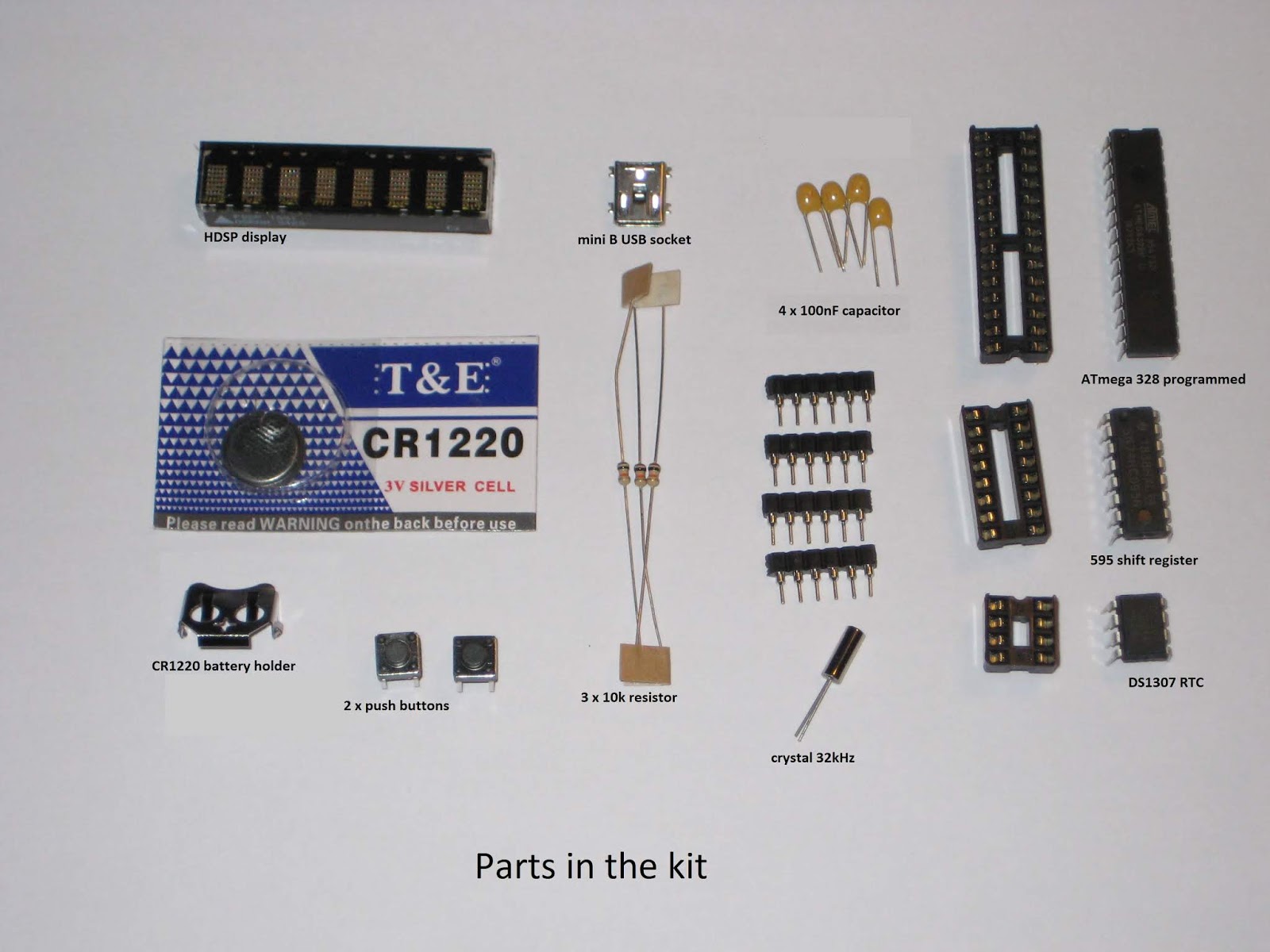


Use a mini B USB cable to power the clock. It should work right away, since the processor is already programmed with the clock software. Use the "Hours" (left) and "Minutes" (right) buttons to set up the time.
Also, insert the CR1220 battery into the holder, to make sure the DS1307 RTC (real time clock) keeps time when the clock board is not powered from USB. Note that the small coin battery ONLY powers the RTC integrated circuit, and not the whole clock. The display is lit when connected to the USB power.
[original story: Wise time with Arduino]