Posts with «text» label

Project: Clock Four – Scrolling text clock

Introduction

Time for another instalment in my highly-irregular series of irregular clock projects.  In this we have “Clock Four” – a scrolling text clock. After examining some Freetronics Dot Matrix Displays in the stock, it occurred to me that it would be neat to display the time as it was spoken (or close to it) – and thus this the clock was born. It is a quick project – we give you enough to get going with the hardware and sketch, and then you can take it further to suit your needs.

Hardware

You’ll need three major items – An Arduino Uno-compatible board, a real-time clock circuit or module using either a DS1307 or DS3232 IC, and a Freetronics DMD. You might want an external power supply, but we’ll get to that later on.

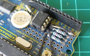
The first stage is to fit your real-time clock. If you are unfamiliar with the operation of real-time clock circuits, check out the last section of this tutorial. You can build a RTC circuit onto a protoshield or if you have a Freetronics Eleven, it can all fit in the prototyping space as such:

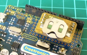
If you have an RTC module, it will also fit in the same space, then you simply run some wires to the 5V, GND, A4 (for SDA) and A5 (for SCL):

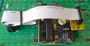
By now I hope you’re thinking “how do you set the time?”. There’s two answers to that question. If you’re using the DS3232 just set it in the sketch (see below) as the accuracy is very good, you only need to upload the sketch with the new time twice a year to cover daylight savings (unless you live in Queensland). Otherwise add a simple user-interface – a couple of buttons could do it, just as we did with Clock Two. Finally you just need to put the hardware on the back of the DMD. There’s plenty of scope to meet your own needs, a simple solution might be to align the control board so you can access the USB socket with ease – and then stick it down with some Sugru:

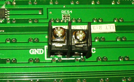
With regards to powering the clock – you can run ONE DMD from the Arduino, and it runs at a good brightness for indoor use. If you want the DMD to run at full, retina-burning brightness you need to use a separate 5 V 4 A power supply. If you’re using two DMDs – that goes to 8 A, and so on. Simply connect the external power to one DMD’s terminals (connect the second or more DMDs to these terminals):
The Arduino Sketch

You can download the sketch from here. Please use IDE v1.0.1 . The sketch has the usual functions to set and retrieve the time from DS1307/3232 real-time clock ICs, and as usual with all our clocks you can enter the time information into the variables in void setup(), then uncomment setDateDs1307(), upload the sketch, re-comment setDateDs1307, then upload the sketch once more. Repeat that process to re-set the time if you didn’t add any hardware-based user interface.

Once the time is retrieved in void loop(), it is passed to the function createTextTime(). This function creates the text string to display by starting with “It’s “, and then determines which words to follow depending on the current time. Finally the function drawText() converts the string holding the text to display into a character variable which can be passed to the DMD.

And here it is in action:

Conclusion

This was a quick project, however I hope you found it either entertaining or useful – and another random type of clock that’s easy to reproduce or modify yourself. We’re already working on another one which is completely different, so stay tuned.

In the meanwhile have fun and keep checking into tronixstuff.com. Why not follow things on twitterGoogle+, subscribe  for email updates or RSS using the links on the right-hand column? And join our friendly Google Group – dedicated to the projects and related items on this website. Sign up – it’s free, helpful to each other –  and we can all learn something.

The post Project: Clock Four – Scrolling text clock appeared first on tronixstuff.

Doorbell Alert System That Sends You a Text and a Photo

What do you do when you have an arduino, a camera, an ethernet shield and a doorbell? You make your own intelligent security system.

The system is actually pretty simple. When the doorbell rings an Arduino sends a request to a notification service called PushingBox which then grabs a picture from web camera located outside. Then PushingBox sends a notification to an iPhone (it looks like this can be modded slightly with PushingBox to include Android and Windows Phone as well) and an email with a picture attached.

Via:[Lifehacker]

Arduino Blog 13 May 18:36
arduino  doorbell  ethernet  text  

Reading from a Text File and Sending to Arduino

The following tutorial will demonstrate how to Read values from a Text file (.txt, .csv) to blink 1 of 9 LEDs attached to an Arduino. It uses the combination of an Arduino and Processing program to process the file. The Processing program will read the text file in real time, only sending new information to the Arduino.


Components Required

  • Arduino UNO
  • Breadboard
  • 9 LEDs
  • 9 x 330 ohm resistors
  • Wires to connect the circuit
  • USB connection cable: to connect the computer to the Arduino
  • A computer: to run the processing sketch, and to compile / upload the Arduino sketch
  • Processing Program installed on computer
  • Arduino Program installed on the computer
  • A comma separated text file (*.txt).


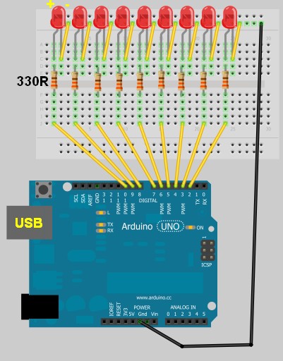
Arduino Layout


The Text File

  • Open Notepad or equivalent text file editor, and paste the following data into it.

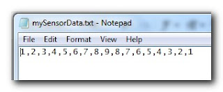
1,2,3,4,5,6,7,8,9,8,7,6,5,4,3,2,1

  • Save the file on your hard drive. In my case, I have chosen to save the file at this location.

D:/mySensorData.txt

  • It should look like the following screenshot


Additional notes regarding the Text file:
  • Just remember what you call it, and where you saved it, because we will be referring to this file later on in the Processing script.
  • Keep all values on the same line.
  • Separate each number with a comma.
  • The number 1 will blink the first LED which is attached to Pin 2 on the Arduino.
  • The number 9 will blink the last LED which is attached to Pin 10 on the Arduino.


Processing Code

You can download the Processing IDE from this site.

 1
2
3
4
5
6
7
8
9
10
11
12
13
14
15
16
17
18
19
20
21
22
23
24
25
26
27
28
29
30
31
32
33
34
35
36
37
38
39
40
41
42
43
44
45
46
47
48
49
50
51
52
53
54
55
56
57
58
59
60
61
62
63
64
65
66
67
68
69
70
71
72
73
74
75
76
77
78
79

style="color: blue;">import
processing.serial.*;

style="color: blue;">import
java.io.*;

style="color: rgb(43, 145, 175);">int
mySwitch=0;

style="color: rgb(43, 145, 175);">int
counter=0;
String [] subtext;
Serial myPort;


style="color: rgb(43, 145, 175);">void
setup(){

style="color: green;">//Create a switch that will control the frequency of text file reads.


style="color: green;">//When mySwitch=1, the program is setup to read the text file.


style="color: green;">//This is turned off when mySwitch = 0

mySwitch=1;


style="color: green;">//Open the serial port for communication with the Arduino


style="color: green;">//Make sure the COM port is correct

myPort =
style="color: blue;">new
Serial(this,
style="color: rgb(163, 21, 21);">"COM6"
, 9600);
myPort.bufferUntil(
style="color: rgb(163, 21, 21);">'\n'
);
}


style="color: rgb(43, 145, 175);">void
draw() {

style="color: blue;">if
(mySwitch>0){

style="color: green;">/*The readData function can be found later in the code.


style="color: green;"> This is the call to read a CSV file on the computer hard-drive. */

readData(
style="color: rgb(163, 21, 21);">"D:/mySensorData.txt"
);


style="color: green;">/*The following switch prevents continuous reading of the text file, until


style="color: green;"> we are ready to read the file again. */

mySwitch=0;
}

style="color: green;">/*Only send new data. This IF statement will allow new data to be sent to


style="color: green;"> the arduino. */


style="color: blue;">if
(counter<subtext.length){

style="color: green;">/* Write the next number to the Serial port and send it to the Arduino


style="color: green;"> There will be a delay of half a second before the command is


style="color: green;"> sent to turn the LED off : myPort.write('0'); */

myPort.write(subtext[counter]);
delay(500);
myPort.write(
style="color: rgb(163, 21, 21);">'0'
);
delay(100);

style="color: green;">//Increment the counter so that the next number is sent to the arduino.

counter++;
}
style="color: blue;">else
{
//If the text file has run out of numbers, then read the text file again in 5 seconds.
delay(5000);
mySwitch=1;
}
}


style="color: green;">/* The following function will read from a CSV or TXT file */


style="color: rgb(43, 145, 175);">void
readData(String myFileName){

File file=
style="color: blue;">new
File(myFileName);
BufferedReader br=
style="color: blue;">null
;

try{
br=
style="color: blue;">new
BufferedReader(
style="color: blue;">new
FileReader(file));
String text=
style="color: blue;">null
;


style="color: green;">/* keep reading each line until you get to the end of the file */


style="color: blue;">while
((text=br.readLine())!=
style="color: blue;">null
){
/* Spilt each line up into bits and pieces using a comma as a separator */
subtext = splitTokens(text,
style="color: rgb(163, 21, 21);">","
);
}
}
style="color: blue;">catch
(FileNotFoundException e){
e.printStackTrace();
}
style="color: blue;">catch
(IOException e){
e.printStackTrace();
}
style="color: blue;">finally
{
try {

style="color: blue;">if
(br != null){
br.close();
}
}
style="color: blue;">catch
(IOException e) {
e.printStackTrace();
}
}
}

I used this site to highlight and format my code.

Once you have copied the text above into the Processing IDE, you can now start working on the Arduino code as seen below.


Arduino Code

You can download the Arduino IDE from this site.

Copy and paste the following code into the Arduino IDE.

 1
2
3
4
5
6
7
8
9
10
11
12
13
14
15
16
17
18
19
20
21
22
23
24
25
26
27
28
29
30
31
32
33
34
35
36
37
38
39
40
41
42
43
44
45
46
47
48
49

style="color: green;">/* This program was created by ScottC on 8/5/2012 to receive serial


style="color: green;">signals from a computer to turn on/off 1-9 LEDs */


style="color: rgb(43, 145, 175);">void
setup() {

style="color: green;">// initialize the digital pins as an output.

pinMode(2, OUTPUT);
pinMode(3, OUTPUT);
pinMode(4, OUTPUT);
pinMode(5, OUTPUT);
pinMode(6, OUTPUT);
pinMode(7, OUTPUT);
pinMode(8, OUTPUT);
pinMode(9, OUTPUT);
pinMode(10, OUTPUT);

style="color: green;">// Turn the Serial Protocol ON

Serial.begin(9600);
}


style="color: rgb(43, 145, 175);">void
loop() {

style="color: rgb(43, 145, 175);">byte
byteRead;


style="color: green;">/* check if data has been sent from the computer: */


style="color: blue;">if
(Serial.available()) {


style="color: green;">/* read the most recent byte */

byteRead = Serial.read();

style="color: green;">//You have to subtract '0' from the read Byte to convert from text to a number.

byteRead=byteRead-
style="color: rgb(163, 21, 21);">'0'
;


style="color: green;">//Turn off all LEDs if the byte Read = 0


style="color: blue;">if
(byteRead==0){

style="color: green;">//Turn off all LEDS

digitalWrite(2, LOW);
digitalWrite(3, LOW);
digitalWrite(4, LOW);
digitalWrite(5, LOW);
digitalWrite(6, LOW);
digitalWrite(7, LOW);
digitalWrite(8, LOW);
digitalWrite(9, LOW);
digitalWrite(10, LOW);
}


style="color: green;">//Turn LED ON depending on the byte Read.


style="color: blue;">if
(byteRead>0){
digitalWrite((byteRead+1), HIGH);
style="color: green;">// set the LED on

}
}
}

Additional Information:
  • The Arduino code will still work without the processing program. You can open the serial monitor window to send the commands to the Arduino manually. In fact, if you encounter any problems, I would suggest you do this. It will help to identify the root cause of the problem (ie Processing or Arduino Code, or physical connections).
  • If you choose to use the Serial Monitor feature of the Arduino IDE, you cannot use the Processing program at the same time.

Once you have assembled the Arduino with all the wires, LEDs, resistors etc, you should now be ready to put it all together and get this baby cranking!


Connecting it all together

  • Connect the USB cable from your computer to the Arduino, and upload the code.
  • Keep the USB cable connected between the Arduino and the computer, as this will become the physical connection needed by the Processing Program
  • Make sure that you have the text file in the correct location on your hard drive, and that it only contains numbers relevant to the code provided (separated by commas).
  • Run the Processing program and watch the LEDs blink in the sequence described by the text file.
  • You can add more numbers to the end of the line, however, the processing program will not be aware of them until you save the file. The text file does not have to be closed.
Other programs can be used to create text file, but you will need the processing program to read the file and send the values to the Arduino. The Arduino will receive each value and react appropriately.

SIMILAR PROJECT: Use a mouse to control the LEDs on your Arduino - see this post.


An alternative Processing Sketch

This Processing sketch uses the loadStrings()method instead of the FileReader method used in the first sketch. This sketch also provides better control over sending the values to the Arduino. When the sketch first loads, the application window will be red. By clicking your mouse inside the window, the background will turn green and the file will be imported and sent to the Arduino, with every value being sent at half second intervals. If you update the text file and save, only new values will be transmitted, however, if you want the entire file to transmit again, you can press the window once (to reset the counter), and then again to read the file and send the values again from the beginning of the file.
I personally like this updated version better than the first, plus I was inspired to update this blog posting due to the fact that some people were having problems with the FileReader method in the first sketch. But both sketches should work (they worked for me).


 1
2
3
4
5
6
7
8
9
10
11
12
13
14
15
16
17
18
19
20
21
22
23
24
25
26
27
28
29
30
31
32
33
34
35
36
37
38
39
40
41
42
43
44
45
46
47
48
49
50
51
52
53
54
55
56
57
58
59
60
61
62

style="color: rgb(0, 128, 0);">/* TextFile Sender: Written by Scott C on 5th April 2013


style="color: rgb(0, 128, 0);"> using Processing Version 2.0b8 */


import processing.serial.*;

Serial comPort;

style="color: rgb(43, 145, 175);">int
counter=0;
style="color: rgb(0, 128, 0);">// Helps to keep track of values sent.


style="color: rgb(43, 145, 175);">int
numItems=0;
style="color: rgb(0, 128, 0);">//Keep track of the number of values in text file

boolean sendStrings=
style="color: rgb(0, 0, 255);">false
;
style="color: rgb(0, 128, 0);">//Turns sending on and off

StringLoader sLoader;
style="color: rgb(0, 128, 0);">//Used to send values to Arduino


style="color: rgb(43, 145, 175);">void
setup(){
comPort =
style="color: rgb(0, 0, 255);">new
Serial(
style="color: rgb(0, 0, 255);">this
, Serial.list()[0], 9600);
background(255,0,0);
style="color: rgb(0, 128, 0);">//Start with a Red background

}


style="color: rgb(43, 145, 175);">void
draw(){
}


style="color: rgb(43, 145, 175);">void
mousePressed() {

style="color: rgb(0, 128, 0);">//Toggle between sending values and not sending values

sendStrings=!sendStrings;


style="color: rgb(0, 128, 0);">//If sendStrings is True - then send values to Arduino


style="color: rgb(0, 0, 255);">if
(sendStrings){
background(0,255,0);
style="color: rgb(0, 128, 0);">//Change the background to green


style="color: rgb(0, 128, 0);">/*When the background is green, transmit


style="color: rgb(0, 128, 0);"> text file values to the Arduino */

sLoader=
style="color: rgb(0, 0, 255);">new
StringLoader();
sLoader.start();
}
style="color: rgb(0, 0, 255);">else
{
background(255,0,0);
style="color: rgb(0, 128, 0);">//Change background to red


style="color: rgb(0, 128, 0);">//Reset the counter

counter=0;
}
}


style="color: rgb(0, 128, 0);">/*============================================================*/


style="color: rgb(0, 128, 0);">/* The StringLoader class imports data from a text file


style="color: rgb(0, 128, 0);"> on a new Thread and sends each value once every half second */


style="color: rgb(0, 0, 255);">public

style="color: rgb(0, 0, 255);">class

style="color: rgb(43, 145, 175);">StringLoader
extends Thread{


style="color: rgb(0, 0, 255);">public
StringLoader(){

style="color: rgb(0, 128, 0);">//default constructor

}


style="color: rgb(0, 0, 255);">public

style="color: rgb(43, 145, 175);">void
run() {
String textFileLines[]=loadStrings(
style="color: rgb(163, 21, 21);">"d:/mySensorData.txt"
);
String lineItems[]=splitTokens(textFileLines[0],
style="color: rgb(163, 21, 21);">","
);
numItems=lineItems.length;

style="color: rgb(0, 0, 255);">for
(
style="color: rgb(43, 145, 175);">int
i = counter; i<numItems; i++){
comPort.write(lineItems[i]);
delay(500);
comPort.write(
style="color: rgb(163, 21, 21);">"0"
);
}
counter=numItems;
}
}


ScottC 09 May 14:09