Introduction
This is the second in a series of tutorials examining various uses of the Arduino Yún. In this article we’ll examine how your Arduino Yún can send data that it captures from the analogue and digital inputs and a real-time clock IC to an online Google Docs spreadsheet. Doing so gives you a neat and inexpensive method of capturing data in real-time and having the ability to analyse the data from almost anywhere, and export it with very little effort.
Getting Started
If you haven’t already done so, ensure your Arduino Yún can connect to your network via WiFi or cable – and get a Temboo account (we run through this here). And you need (at the time of writing) IDE version 1.5.4 which can be downloaded from the Arduino website. Finally, you will need a Google account, so if you don’t have one – sign up here.

Testing the Arduino Yún-Google Docs connection
In this first example we’ll run through the sketch provided by Temboo so you can confirm everything works as it should. First of all, create a spreadsheet in Google Docs. Call it “ArduinoData” and label the first two columns as “time” and “sensor”, as shown in the screen shot below:

Always label the required columns. You can call them whatever you need. For new Google users, the URL shown in my example will be different to yours. Next, copy the following sketch to the IDE:
/*
  SendDataToGoogleSpreadsheet

  Demonstrates appending a row of data to a Google spreadsheet from the Arduino Yun
  using the Temboo Arduino Yun SDK.

  This example code is in the public domain.

*/

#include <Bridge.h>
#include <Temboo.h>
#include "TembooAccount.h" // contains Temboo account information

/*** SUBSTITUTE YOUR VALUES BELOW: ***/

// Note that for additional security and reusability, you could
// use #define statements to specify these values in a .h file.

const String GOOGLE_USERNAME = "your-google-username";
const String GOOGLE_PASSWORD = "your-google-password";

// the title of the spreadsheet you want to send data to
// (Note that this must actually be the title of a Google spreadsheet
// that exists in your Google Drive/Docs account, and is configured
// as described above.)
const String SPREADSHEET_TITLE = "your-spreadsheet-title";

const unsigned long RUN_INTERVAL_MILLIS = 60000; // how often to run the Choreo (in milliseconds)

// the last time we ran the Choreo
// (initialized to 60 seconds ago so the
// Choreo is run immediately when we start up)
unsigned long lastRun = (unsigned long)-60000;

void setup() {

  // for debugging, wait until a serial console is connected
  Serial.begin(9600);
  delay(4000);
  while(!Serial);

  Serial.print("Initializing the bridge...");
  Bridge.begin();
  Serial.println("Done");
}

void loop()
{
  // get the number of milliseconds this sketch has been running
  unsigned long now = millis();

  // run again if it's been 60 seconds since we last ran
  if (now - lastRun >= RUN_INTERVAL_MILLIS) {

    // remember 'now' as the last time we ran the choreo
    lastRun = now;

    Serial.println("Getting sensor value...");

    // get the value we want to append to our spreadsheet
    unsigned long sensorValue = getSensorValue();

    Serial.println("Appending value to spreadsheet...");

    // we need a Process object to send a Choreo request to Temboo
    TembooChoreo AppendRowChoreo;

    // invoke the Temboo client
    // NOTE that the client must be reinvoked and repopulated with
    // appropriate arguments each time its run() method is called.
    AppendRowChoreo.begin();

    // set Temboo account credentials
    AppendRowChoreo.setAccountName(TEMBOO_ACCOUNT);
    AppendRowChoreo.setAppKeyName(TEMBOO_APP_KEY_NAME);
    AppendRowChoreo.setAppKey(TEMBOO_APP_KEY);

    // identify the Temboo Library choreo to run (Google > Spreadsheets > AppendRow)
    AppendRowChoreo.setChoreo("/Library/Google/Spreadsheets/AppendRow");

    // set the required Choreo inputs
    // see https://www.temboo.com/library/Library/Google/Spreadsheets/AppendRow/
    // for complete details about the inputs for this Choreo

    // your Google username (usually your email address)
    AppendRowChoreo.addInput("Username", GOOGLE_USERNAME);

    // your Google account password
    AppendRowChoreo.addInput("Password", GOOGLE_PASSWORD);

    // the title of the spreadsheet you want to append to
    AppendRowChoreo.addInput("SpreadsheetTitle", SPREADSHEET_TITLE);

    // convert the time and sensor values to a comma separated string
    String rowData(now);
    rowData += ",";
    rowData += sensorValue;

    // add the RowData input item
    AppendRowChoreo.addInput("RowData", rowData);

    // run the Choreo and wait for the results
    // The return code (returnCode) will indicate success or failure
    unsigned int returnCode = AppendRowChoreo.run();

    // return code of zero (0) means success
    if (returnCode == 0) {
      Serial.println("Success! Appended " + rowData);
      Serial.println("");
    } else {
      // return code of anything other than zero means failure
      // read and display any error messages
      while (AppendRowChoreo.available()) {
        char c = AppendRowChoreo.read();
        Serial.print(c);
      }
    }

    AppendRowChoreo.close();
  }
}

// this function simulates reading the value of a sensor
unsigned long getSensorValue() {
  return analogRead(A0);
}
Now look for the following two lines in the sketch:
const String GOOGLE_USERNAME = "your-google-username";
const String GOOGLE_PASSWORD = "your-google-password";
This is where you put your Google account username and password. For example, if your Google account is “CI5@gmail.com” and password “RS2000Escort” the two lines will be:
const String GOOGLE_USERNAME = "CI5@gmail.com";
const String GOOGLE_PASSWORD = "RS2000Escort";
Next, you need to insert the spreadsheet name in the sketch. Look for the following line:
const String SPREADSHEET_TITLE = "your-spreadsheet-title";
and change your-spreadsheet-title to ArduinoData.
Finally, create your header file by copying the the header file data from here (after logging to Temboo) into a text file and saving it with the name TembooAccount.h in the same folder as your sketch from above. You know this has been successful when opening the sketch, as you will see the header file in a second tab, for example:

Finally, save and upload your sketch to the Arduino Yún. After a moment or two it will send values to the spreadsheet, and repeat this every sixty seconds – for example:

If your Yún is connected via USB you can also watch the status via the serial monitor.
One really super-cool and convenient feature of using Google Docs is that you can access it from almost anywhere. Desktop, tablet, mobile… and it updates in real-time:

So with your Yún you can capture data and view it from anywhere you can access the Internet. Now let’s do just that.
Sending your own data from the Arduino Yún to a Google Docs Spreadsheet
In this example we’ll demonstrate sending three types of data:
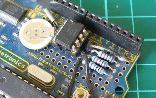
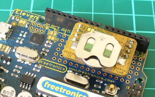
With these types of data you should be able to represent all manner of things. We use the RTC as the time and date from it will match when the data was captured, not when the data was written to the spreadsheet. If you don’t have a DS3232 you can also use a DS1307.
If you’re not familiar with these parts and the required code please review this tutorial. When connecting your RTC – please note that SDA (data) is D2 and SCL (clock) is D3 on the Yún.
The sketch for this example is a modified version of the previous sketch, except we have more data to send. The data is captured into variables from the line:
// get the values from A0 to A3 and D7, D8
You can send whatever data you like, as long as it is all appended to a String by the name of rowdata. When you want to use a new column in the spreadsheet, simply append a comma “,” between the data in the string. In other words, you’re creating a string of CSV (comma-separated values) data. You can see this process happen from the line that has the comment:
// CSV creation starts here!
in the example sketch that follows shortly. Finally, you can alter the update rate of the sketch – it’s set to every 60 seconds, however you can change this by altering the 60000 (milliseconds) in the following line:
const unsigned long RUN_INTERVAL_MILLIS = 60000;
Don’t forget that each update costs you a call and some data from your Temboo account – you only get so many for free then you have to pay for more. Check your Temboo account for more details.
So without further ado, the following sketch will write the values read from A0~A3, the status of D7 and D8 (1 for HIGH, 0 for LOW) along with the current date and time to the spreadsheet. Don’t forget to update the password, username and so on as you did for the first example sketch:
#include <Bridge.h>
#include <Temboo.h>
#include "TembooAccount.h" // contains Temboo account information
#include "Wire.h"
#define DS3232_I2C_ADDRESS 0x68

unsigned long analog0, analog1, analog2, analog3;
int digital7 = 7;
int digital8 = 8;
boolean d7, d8;
byte second, minute, hour, dayOfWeek, dayOfMonth, month, year; // for RTC

const String GOOGLE_USERNAME = "your-google-username";
const String GOOGLE_PASSWORD = "your-google-password";
const String SPREADSHEET_TITLE = "your-spreadsheet-title";

// update interval in milliseconds (every minute would be 60000)
const unsigned long RUN_INTERVAL_MILLIS = 60000;
unsigned long lastRun = (unsigned long)-60000;

void setup()
{
  // activate I2C bus
  Wire.begin();
  // for debugging, wait until a serial console is connected
  Serial.begin(9600);
  delay(4000);
  while(!Serial);
  Serial.print("Initializing the bridge...");
  Bridge.begin();
  Serial.println("Done");
  // Set up digital inputs to monitor
  pinMode(digital7, INPUT);
  pinMode(digital8, INPUT);
}

// for RTC
// Convert normal decimal numbers to binary coded decimal
byte decToBcd(byte val)
{
  return ( (val/10*16) + (val%10) );
}

// Convert binary coded decimal to normal decimal numbers
byte bcdToDec(byte val)
{
  return ( (val/16*10) + (val%16) );
}

void readDS3232time(byte *second,
byte *minute,
byte *hour,
byte *dayOfWeek,
byte *dayOfMonth,
byte *month,
byte *year)
{
  Wire.beginTransmission(DS3232_I2C_ADDRESS);
  Wire.write(0); // set DS3232 register pointer to 00h
  Wire.endTransmission();
  Wire.requestFrom(DS3232_I2C_ADDRESS, 7); // request 7 bytes of data from DS3232 starting from register 00h
  // A few of these need masks because certain bits are control bits
  *second     = bcdToDec(Wire.read() & 0x7f);
  *minute     = bcdToDec(Wire.read());
  *hour       = bcdToDec(Wire.read() & 0x3f);  // Need to change this if 12 hour am/pm
  *dayOfWeek  = bcdToDec(Wire.read());
  *dayOfMonth = bcdToDec(Wire.read());
  *month      = bcdToDec(Wire.read());
  *year       = bcdToDec(Wire.read());
}

void setDS3232time(byte second, byte minute, byte hour, byte dayOfWeek, byte dayOfMonth, byte month, byte year)
// sets time and date data to DS3232
{
  Wire.beginTransmission(DS3232_I2C_ADDRESS);
  Wire.write(0); // sends 00h - seconds register
  Wire.write(decToBcd(second));     // set seconds
  Wire.write(decToBcd(minute));     // set minutes
  Wire.write(decToBcd(hour));       // set hours
  Wire.write(decToBcd(dayOfWeek));  // set day of week (1=Sunday, 7=Saturday)
  Wire.write(decToBcd(dayOfMonth)); // set date (1~31)
  Wire.write(decToBcd(month));      // set month
  Wire.write(decToBcd(year));       // set year (0~99)
  Wire.endTransmission();
}

void loop()
{
  // get the number of milliseconds this sketch has been running
  unsigned long now = millis();

  // run again if it's been 60 seconds since we last ran
  if (now - lastRun >= RUN_INTERVAL_MILLIS) {

    // remember 'now' as the last time we ran the choreo
    lastRun = now;
    Serial.println("Getting sensor values...");
    // get the values from A0 to A3 and D7, D8
    analog0 = analogRead(0);
    analog1 = analogRead(1);
    analog2 = analogRead(2);
    analog3 = analogRead(3);
    d7 = digitalRead(digital7);
    d8 = digitalRead(digital8);

    Serial.println("Appending value to spreadsheet...");
    // we need a Process object to send a Choreo request to Temboo
    TembooChoreo AppendRowChoreo;

    // invoke the Temboo client
    // NOTE that the client must be reinvoked and repopulated with
    // appropriate arguments each time its run() method is called.
    AppendRowChoreo.begin();

    // set Temboo account credentials
    AppendRowChoreo.setAccountName(TEMBOO_ACCOUNT);
    AppendRowChoreo.setAppKeyName(TEMBOO_APP_KEY_NAME);
    AppendRowChoreo.setAppKey(TEMBOO_APP_KEY);

    // identify the Temboo Library choreo to run (Google > Spreadsheets > AppendRow)
    AppendRowChoreo.setChoreo("/Library/Google/Spreadsheets/AppendRow");
    // your Google username (usually your email address)
    AppendRowChoreo.addInput("Username", GOOGLE_USERNAME);
    // your Google account password
    AppendRowChoreo.addInput("Password", GOOGLE_PASSWORD);
    // the title of the spreadsheet you want to append to
    AppendRowChoreo.addInput("SpreadsheetTitle", SPREADSHEET_TITLE);

    // get time and date from RTC
    readDS3232time(&second, &minute, &hour, &dayOfWeek, &dayOfMonth, &month, &year);

    // smoosh all the sensor, date and time data into a String
    // CSV creation starts here!
    String rowData(analog0);
    rowData += ",";
    rowData += analog1;
    rowData += ",";
    rowData += analog2;
    rowData += ",";
    rowData += analog3;
    rowData += ",";
    rowData += d7;
    rowData += ",";
    rowData += d8;
    rowData += ",";
    // insert date
    rowData += dayOfMonth;
    rowData += "/";
    rowData += month;
    rowData += "/20";
    rowData += year;
    rowData += ",";
    // insert time
    rowData += hour;
    if (minute<10)
    {
        rowData += "0";
    }
    rowData += minute;
    rowData += ".";
    if (second<10)
    {
        rowData += "0";
    }
    rowData += second;
    rowData += "h";

    // add the RowData input item
    AppendRowChoreo.addInput("RowData", rowData);

    // run the Choreo and wait for the results
    // The return code (returnCode) will indicate success or failure
    unsigned int returnCode = AppendRowChoreo.run();

    // return code of zero (0) means success
    if (returnCode == 0) {
      Serial.println("Success! Appended " + rowData);
      Serial.println("");
    } else {
      // return code of anything other than zero means failure
      // read and display any error messages
      while (AppendRowChoreo.available()) {
        char c = AppendRowChoreo.read();
        Serial.print(c);
      }
    }
    AppendRowChoreo.close();
  }
}
… which in our example resulted with the following:

… and here is a video that shows how the spreadsheet updates in real time across multiple devices:
Conclusion
It’s no secret that the Yún isn’t the cheapest devleopment board around, however the ease of use as demonstrated in this tutorial shows that the time saved in setup and application is more than worth the purchase price of the board and extra Temboo credits if required.
And if you’re interested in learning more about Arduino, or want to introduce someone else to the interesting world of Arduino – check out my book (now in a third printing!) “Arduino Workshop” from No Starch Press.

In the meanwhile have fun and keep checking into tronixstuff.com. Why not follow things on twitter, Google+, subscribe for email updates or RSS using the links on the right-hand column? And join our friendly Google Group – dedicated to the projects and related items on this website. Sign up – it’s free, helpful to each other – and we can all learn something.
The post Tutorial – Google Docs and the Arduino Yún appeared first on tronixstuff.