Posts with «learning» label

Brazillian Class Creates Digital Board Game

A class in Brazil was given the assignment to make a board game. [Marcelo], presumably, heard his son lamenting how lame it was going to be if the board was just cardboard with some drawings on, and came to the rescue.

A match meant to be.

Working with the class, they came up with the rules of the game. We’re not certain what those are, but it involves a regular game board, a flashing light circle with numbers, and a fusion between Operation and one of those disease transmitters commonly found at the doctor’s office. You can try to puzzle them out from the video after the break.

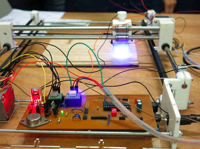
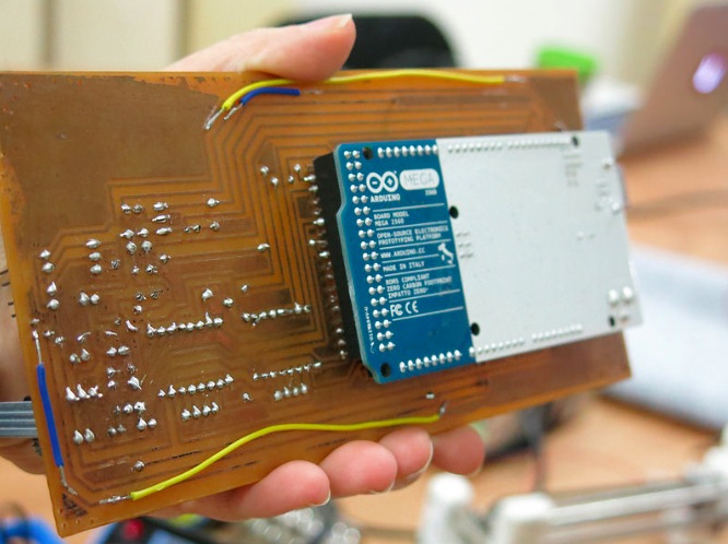
The brains of the board is an Arduino with an external EEPROM for all the sound effects and other data needed for this construction. Everything is laid out on a beautifully done home etched PCB. It’s too bad the other side of the board isn’t visible.

We’re sure the kids learned a lot working with [Marcelo]. It would have been nice if a traveling wizard came to some of our earlier classes in school and showed us just how much cool stuff you can do if you know electronics.


Filed under: Arduino Hacks

NeoPixel Heart Beat Display


Project Description


In this project, your heart will control a mesmerising LED sequence on a 5 metre Neopixel LED strip with a ws2812B chipset. Every heart beat will trigger a LED animation that will keep you captivated and attached to your Arduino for ages. The good thing about this project is that it is relatively easy to set up, and requires no soldering. The hardest part is downloading and installing the FastLED library into the Arduino IDE, but that in itself is not too difficult. The inspiration and idea behind this project came from Ali Murtaza, who wanted to know how to get an LED strip to pulse to his heart beat.
 
Have a look at the video below to see this project in action.


The Video


Parts Required:


Power Requirements

Before you start any LED strip project, the first thing you will need to think about is POWER. According to the Adafruit website, each individual NeoPixel LED can draw up to 60 milliamps at maximum brightness - white. Therefore the amount of current required for the entire strip will be way more than your Arduino can handle. If you try to power this LED strip directly from your Arduino, you run the risk of damaging not only your Arduino, but your USB port as well. The Arduino will be used to control the LED strip, but the LED strip will need to be powered by a separate power supply. The power supply you choose to use is important. It must provide the correct voltage, and must able to supply sufficient current.
 

Operating Voltage (5V)

The operating voltage of the NeoPixel strip is 5 volts DC. Excessive voltage will damage/destroy your NeoPixels.

Current requirements (9.0 Amps)

OpenLab recommend the use of a 5V 10A power supply. Having more Amps is OK, providing the output voltage is 5V DC. The LEDs will only draw as much current as they need. To calculate the amount of current this 5m strip can draw with all LEDs turned on at full brightness - white:

30 NeoPixel LEDs x 60mA x 5m = 9000mA = 9.0 Amps for a 5 metre strip.

Therefore a 5V 10A power supply would be able to handle the maximum current (9.0 Amps) demanded by a 5m NeoPixel strip containing a total of 150 LEDs.


Arduino Libraries and IDE


Before you start to hook up any components, upload the following sketch to the Arduino microcontroller. I am assuming that you already have the Arduino IDE installed on your computer. If not, the IDE can be downloaded from here.
 
The FastLED library is useful for simplifying the code for programming the NeoPixels. The latest "FastLED library" can be downloaded from here. I used FastLED library version 3.0.3 in this project.
 
If you have a different LED strip or your NeoPixels have a different chipset, make sure to change the relevant lines of code to accomodate your hardware. I would suggest you try out a few of the FastLED library examples before using the code below, so that you become more familiar with the library, and will be better equipped to make the necessary changes. If you have a 5 metre length of the NeoPixel 30 LED/m strip with the ws2812B chipset, then you will not have to make any modification below.
 

ARDUINO CODE:


1
2
3
4
5
6
7
8
9
10
11
12
13
14
15
16
17
18
19
20
21
22
23
24
25
26
27
28
29
30
31
32
33
34
35
36
37
38
39
40
41
42
43
44
45
46
47
48
49
50
51
52
53
54
55
56
57
58
59
60
61
62
63
64
65
66
67
68
69
70
71
72
73
74
75
76
77
78
79
80
81
82
83
84
85
86
87
88
89
90
91
92
93
94
95
96
97
98
99
100
101
102
103
104
105
106
107
108
109
110
111
112
113
114
115
116
117
118
119
120
121
122
123
124
125
126
127
128
129
130
131
132
133
134
135
136
137
138
139
140
/* ================================================================================================ Project: NeoPixel Heart Beat Display Neopixel chipset: ws2812B (30 LED/m strip) Author: Scott C Created: 8th July 2015 Arduino IDE: 1.6.4 Website: http://arduinobasics.blogspot.com/p/arduino-basics-projects-page.html Description: This sketch will display a heart beat on a 5m Neopixel LED strip. Requires a Grove Ear-clip heart rate sensor and a Neopixel strip. This project makes use of the FastLED library: http://fastled.io/ You may need to modify the code below to accomodate your specific LED strip. See the FastLED library site for more details. ================================================================================================== */ //This project needs the FastLED library - link in the description. #include "FastLED.h" //The total number of LEDs being used is 150 #define NUM_LEDS 150 // The data pin for the NeoPixel strip is connected to digital Pin 6 on the Arduino #define DATA_PIN 6 //Attach the Grove Ear-clip heart rate sensor to digital pin 2 on the Arduino. #define EAR_CLIP 2 //Initialise the LED array CRGB leds[NUM_LEDS]; //Initialise the global variables used to control the LED animation int ledNum = 0; //Keep track of the LEDs boolean beated = false; //Used to identify when the heart has beated int randomR = 0; //randomR used to randomise the fade-out of the LEDs //================================================================================================ // setup() : Is used to initialise the LED strip //================================================================================================ void setup() { FastLED.addLeds<NEOPIXEL,DATA_PIN>(leds, NUM_LEDS); //Set digital pin 2 (Ear-clip heart rate sensor) as an INPUT pinMode(EAR_CLIP, INPUT);} //================================================================================================ // loop() : Take readings from the Ear-clip sensor, and display the animation on the LED strip //================================================================================================ void loop() { //If the Ear-clip sensor moves from LOW to HIGH, call the beatTriggered method if(digitalRead(EAR_CLIP)>0){ //beatTriggered() is only called if the 'beated' variable is false. //This prevents multiple triggers from the same beat. ifbeated){ beatTriggered(); } } else { beated = false; //Change the 'beated' variable to false when the Ear-clip heart rate sensor is reading LOW. } //Fade the LEDs by 1 unit/cycle, when the heart is at 'rest' (i.e. between beats) fadeLEDs(5);} //================================================================================================ // beatTriggered() : This is the LED animation sequence when the heart beats //================================================================================================ void beatTriggered(){ //Ignite 30 LEDs with a red value between 0 to 255 for(int i = 0; i<30; i++){ //The red channel is randomised to a value between 0 to 255 leds[ledNum].r=random8(); FastLED.show(); //Call the fadeLEDs method after every 3rd LED is lit. if(ledNum%3==0){ fadeLEDs(5); } //Move to the next LED ledNum++; //Make sure to move back to the beginning if the animation falls off the end of the strip if(ledNum>(NUM_LEDS-1)){ ledNum=0; } } //Ignite 20 LEDS with a blue value between 0 to 120 for(int i = 0; i<20; i++){ //The blue channel is randomised to a value between 0 to 120 leds[ledNum].b=random8(120); FastLED.show(); //Call the fadeLEDs method after every 3rd LED is lit. if(ledNum%3==0){ fadeLEDs(5); } //Move to the next LED ledNum++; //Make sure to move back to the beginning if the animation falls off the end of the strip if(ledNum>(NUM_LEDS-1)){ ledNum=0; } } //Change the 'beated' variable to true, until the Ear-Clip sensor reads LOW. beated=true;} //================================================================================================ // fadeLEDs() : The fading effect of the LEDs when the Heart is resting (Ear-clip reads LOW) //================================================================================================ void fadeLEDs(int fadeVal){ for (int i = 0; i<NUM_LEDS; i++){ //Fade every LED by the fadeVal amount leds[i].fadeToBlackBy( fadeVal ); //Randomly re-fuel some of the LEDs that are currently lit (1% chance per cycle) //This enhances the twinkling effect. if(leds[i].r>10){ randomR = random8(100); if(randomR<1){ //Set the red channel to a value of 80 leds[i].r=80; //Increase the green channel to 20 - to add to the effect leds[i].g=20; } } } FastLED.show();}


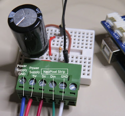
NeoPixel Strip connection

The NeoPixel strip is rolled up when you first get it. You will notice that there are wires on both sides of the strip. This allows you to chain LED strips together to make longer strips. The more LEDs you have, the more current you will need. Connect your Arduino and power supply to the left side of the strip, with the arrows pointing to the right. (i.e. the side with the "female" jst connector).


NeoPixel Strip Wires

There are 5 wires that come pre-attached to either side of the LED strip.


You don't have to use ALL FIVE wires, however you will need at least one of each colour: red, white & green.


Fritzing sketch

The following diagram will show you how to wire everything together
 
(click to enlarge)

Arduino Power considerations

Please note that the Arduino is powered by a USB cable.
If you plan to power the Arduino from your power supply, you will need to disconnect the USB cable from the Arduino FIRST, then connect a wire from the 5V line on the Power supply to the 5V pin on the Arduino. Do NOT connect the USB cable to the Arduino while the 5V wire is connected to the Arduino.


Large Capacitor

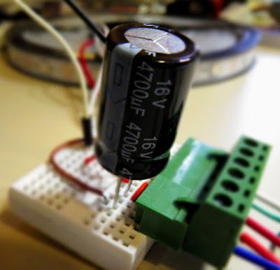
Adafruit also recommend the use of a large capacitor across the + and - terminals of the LED strip to "prevent the initial onrush of current from damaging the pixels". Adafruit recommends a capacitor that is 1000uF, 6.3V or higher. I used a 4700uF 16V Electrolytic Capacitor.


Resistor on Data Pin

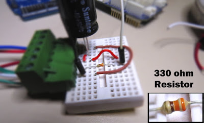
Another recommendation from Adafruit is to place a "300 to 500 Ohm resistor" between the Arduino's data pin and the data input on the first NeoPixel to prevent voltage spikes that can damage the first pixel. I used a 330 Ohm resistor.


Grove Ear-clip heart rate sensor connection

The Grove Base shield makes it easy to connect Grove modules to the Arduino. If you have a Grove Base shield, you will need to connect the Ear-clip heart rate sensor to Digital pin 2 as per the diagram below.


Completed construction

Once you have everything connected, you can plug the USB cable into the Arduino, and turn on the LED power supply. Attach the ear-clip to your ear (or to your finger) and allow a few seconds to allow the sensor to register your pulse. The LED strip will light up with every heart beat with an animation that moves from one end of the strip to the other in just three heart beats. When the ear-clip is not connected to your ear or finger, the LEDs should remain off. However, the ear clip may "trigger" a heart beat when opening or closing the clip.
 
Here is a picture of all the components (fully assembled).


Concluding comments


This very affordable LED strip allows you to create amazing animations over a greater distance. I thought that having less LEDs per metre would make the animations look "jittery", but I was wrong, they look amazing. One of the good things about this strip is the amount of space between each Neopixel, allowing you to easily cut and join the strip to the size and shape you need.
 
This LED strip is compatible with the FastLED library, which makes for easy LED animation programming. While I used this LED strip to display my heart beat, you could just as easily use it to display the output of any other sensor attached to the Arduino.


If you like this page, please do me a favour and show your appreciation :

 
Visit my ArduinoBasics Google + page.
Follow me on Twitter by looking for ScottC @ArduinoBasics.
I can also be found on Pinterest and Instagram.
Have a look at my videos on my YouTube channel.


This project would not have been possible without OpenLab's collaborative effort.
Please visit their site for more cool projects.


However, if you do not have a google profile...
Feel free to share this page with your friends in any way you see fit.

NeoPixel Heart Beat Display


Project Description


In this project, your heart will control a mesmerising LED sequence on a 5 metre Neopixel LED strip with a ws2812B chipset. Every heart beat will trigger a LED animation that will keep you captivated and attached to your Arduino for ages. The good thing about this project is that it is relatively easy to set up, and requires no soldering. The hardest part is downloading and installing the FastLED library into the Arduino IDE, but that in itself is not too difficult. The inspiration and idea behind this project came from Ali Murtaza, who wanted to know how to get an LED strip to pulse to his heart beat.
 
Have a look at the video below to see this project in action.


The Video


Parts Required:


Power Requirements

Before you start any LED strip project, the first thing you will need to think about is POWER. According to the Adafruit website, each individual NeoPixel LED can draw up to 60 milliamps at maximum brightness - white. Therefore the amount of current required for the entire strip will be way more than your Arduino can handle. If you try to power this LED strip directly from your Arduino, you run the risk of damaging not only your Arduino, but your USB port as well. The Arduino will be used to control the LED strip, but the LED strip will need to be powered by a separate power supply. The power supply you choose to use is important. It must provide the correct voltage, and must able to supply sufficient current.
 

Operating Voltage (5V)

The operating voltage of the NeoPixel strip is 5 volts DC. Excessive voltage will damage/destroy your NeoPixels.

Current requirements (9.0 Amps)

OpenLab recommend the use of a 5V 10A power supply. Having more Amps is OK, providing the output voltage is 5V DC. The LEDs will only draw as much current as they need. To calculate the amount of current this 5m strip can draw with all LEDs turned on at full brightness - white:

30 NeoPixel LEDs x 60mA x 5m = 9000mA = 9.0 Amps for a 5 metre strip.

Therefore a 5V 10A power supply would be able to handle the maximum current (9.0 Amps) demanded by a 5m NeoPixel strip containing a total of 150 LEDs.


Arduino Libraries and IDE


Before you start to hook up any components, upload the following sketch to the Arduino microcontroller. I am assuming that you already have the Arduino IDE installed on your computer. If not, the IDE can be downloaded from here.
 
The FastLED library is useful for simplifying the code for programming the NeoPixels. The latest "FastLED library" can be downloaded from here. I used FastLED library version 3.0.3 in this project.
 
If you have a different LED strip or your NeoPixels have a different chipset, make sure to change the relevant lines of code to accomodate your hardware. I would suggest you try out a few of the FastLED library examples before using the code below, so that you become more familiar with the library, and will be better equipped to make the necessary changes. If you have a 5 metre length of the NeoPixel 30 LED/m strip with the ws2812B chipset, then you will not have to make any modification below.
 

ARDUINO CODE:


1
2
3
4
5
6
7
8
9
10
11
12
13
14
15
16
17
18
19
20
21
22
23
24
25
26
27
28
29
30
31
32
33
34
35
36
37
38
39
40
41
42
43
44
45
46
47
48
49
50
51
52
53
54
55
56
57
58
59
60
61
62
63
64
65
66
67
68
69
70
71
72
73
74
75
76
77
78
79
80
81
82
83
84
85
86
87
88
89
90
91
92
93
94
95
96
97
98
99
100
101
102
103
104
105
106
107
108
109
110
111
112
113
114
115
116
117
118
119
120
121
122
123
124
125
126
127
128
129
130
131
132
133
134
135
136
137
138
139
140
/* ================================================================================================ Project: NeoPixel Heart Beat Display Neopixel chipset: ws2812B (30 LED/m strip) Author: Scott C Created: 8th July 2015 Arduino IDE: 1.6.4 Website: http://arduinobasics.blogspot.com/p/arduino-basics-projects-page.html Description: This sketch will display a heart beat on a 5m Neopixel LED strip. Requires a Grove Ear-clip heart rate sensor and a Neopixel strip. This project makes use of the FastLED library: http://fastled.io/ You may need to modify the code below to accomodate your specific LED strip. See the FastLED library site for more details. ================================================================================================== */ //This project needs the FastLED library - link in the description. #include "FastLED.h" //The total number of LEDs being used is 150 #define NUM_LEDS 150 // The data pin for the NeoPixel strip is connected to digital Pin 6 on the Arduino #define DATA_PIN 6 //Attach the Grove Ear-clip heart rate sensor to digital pin 2 on the Arduino. #define EAR_CLIP 2 //Initialise the LED array CRGB leds[NUM_LEDS]; //Initialise the global variables used to control the LED animation int ledNum = 0; //Keep track of the LEDs boolean beated = false; //Used to identify when the heart has beated int randomR = 0; //randomR used to randomise the fade-out of the LEDs //================================================================================================ // setup() : Is used to initialise the LED strip //================================================================================================ void setup() { FastLED.addLeds<NEOPIXEL,DATA_PIN>(leds, NUM_LEDS); //Set digital pin 2 (Ear-clip heart rate sensor) as an INPUT pinMode(EAR_CLIP, INPUT);} //================================================================================================ // loop() : Take readings from the Ear-clip sensor, and display the animation on the LED strip //================================================================================================ void loop() { //If the Ear-clip sensor moves from LOW to HIGH, call the beatTriggered method if(digitalRead(EAR_CLIP)>0){ //beatTriggered() is only called if the 'beated' variable is false. //This prevents multiple triggers from the same beat. ifbeated){ beatTriggered(); } } else { beated = false; //Change the 'beated' variable to false when the Ear-clip heart rate sensor is reading LOW. } //Fade the LEDs by 1 unit/cycle, when the heart is at 'rest' (i.e. between beats) fadeLEDs(5);} //================================================================================================ // beatTriggered() : This is the LED animation sequence when the heart beats //================================================================================================ void beatTriggered(){ //Ignite 30 LEDs with a red value between 0 to 255 for(int i = 0; i<30; i++){ //The red channel is randomised to a value between 0 to 255 leds[ledNum].r=random8(); FastLED.show(); //Call the fadeLEDs method after every 3rd LED is lit. if(ledNum%3==0){ fadeLEDs(5); } //Move to the next LED ledNum++; //Make sure to move back to the beginning if the animation falls off the end of the strip if(ledNum>(NUM_LEDS-1)){ ledNum=0; } } //Ignite 20 LEDS with a blue value between 0 to 120 for(int i = 0; i<20; i++){ //The blue channel is randomised to a value between 0 to 120 leds[ledNum].b=random8(120); FastLED.show(); //Call the fadeLEDs method after every 3rd LED is lit. if(ledNum%3==0){ fadeLEDs(5); } //Move to the next LED ledNum++; //Make sure to move back to the beginning if the animation falls off the end of the strip if(ledNum>(NUM_LEDS-1)){ ledNum=0; } } //Change the 'beated' variable to true, until the Ear-Clip sensor reads LOW. beated=true;} //================================================================================================ // fadeLEDs() : The fading effect of the LEDs when the Heart is resting (Ear-clip reads LOW) //================================================================================================ void fadeLEDs(int fadeVal){ for (int i = 0; i<NUM_LEDS; i++){ //Fade every LED by the fadeVal amount leds[i].fadeToBlackBy( fadeVal ); //Randomly re-fuel some of the LEDs that are currently lit (1% chance per cycle) //This enhances the twinkling effect. if(leds[i].r>10){ randomR = random8(100); if(randomR<1){ //Set the red channel to a value of 80 leds[i].r=80; //Increase the green channel to 20 - to add to the effect leds[i].g=20; } } } FastLED.show();}


NeoPixel Strip connection

The NeoPixel strip is rolled up when you first get it. You will notice that there are wires on both sides of the strip. This allows you to chain LED strips together to make longer strips. The more LEDs you have, the more current you will need. Connect your Arduino and power supply to the left side of the strip, with the arrows pointing to the right. (i.e. the side with the "female" jst connector).


NeoPixel Strip Wires

There are 5 wires that come pre-attached to either side of the LED strip.


You don't have to use ALL FIVE wires, however you will need at least one of each colour: red, white & green.


Fritzing sketch

The following diagram will show you how to wire everything together
 
(click to enlarge)

Arduino Power considerations

Please note that the Arduino is powered by a USB cable.
If you plan to power the Arduino from your power supply, you will need to disconnect the USB cable from the Arduino FIRST, then connect a wire from the 5V line on the Power supply to the VIN pin on the Arduino. Do NOT connect the USB cable to the Arduino while the VIN wire is connected.


Large Capacitor

Adafruit also recommend the use of a large capacitor across the + and - terminals of the LED strip to "prevent the initial onrush of current from damaging the pixels". Adafruit recommends a capacitor that is 1000uF, 6.3V or higher. I used a 4700uF 16V Electrolytic Capacitor.


Resistor on Data Pin

Another recommendation from Adafruit is to place a "300 to 500 Ohm resistor" between the Arduino's data pin and the data input on the first NeoPixel to prevent voltage spikes that can damage the first pixel. I used a 330 Ohm resistor.


Grove Ear-clip heart rate sensor connection

The Grove Base shield makes it easy to connect Grove modules to the Arduino. If you have a Grove Base shield, you will need to connect the Ear-clip heart rate sensor to Digital pin 2 as per the diagram below.


Completed construction

Once you have everything connected, you can plug the USB cable into the Arduino, and turn on the LED power supply. Attach the ear-clip to your ear (or to your finger) and allow a few seconds to allow the sensor to register your pulse. The LED strip will light up with every heart beat with an animation that moves from one end of the strip to the other in just three heart beats. When the ear-clip is not connected to your ear or finger, the LEDs should remain off. However, the ear clip may "trigger" a heart beat when opening or closing the clip.
 
Here is a picture of all the components (fully assembled).


Concluding comments


This very affordable LED strip allows you to create amazing animations over a greater distance. I thought that having less LEDs per metre would make the animations look "jittery", but I was wrong, they look amazing. One of the good things about this strip is the amount of space between each Neopixel, allowing you to easily cut and join the strip to the size and shape you need.
 
This LED strip is compatible with the FastLED library, which makes for easy LED animation programming. While I used this LED strip to display my heart beat, you could just as easily use it to display the output of any other sensor attached to the Arduino.


If you like this page, please do me a favour and show your appreciation :

 
Visit my ArduinoBasics Google + page.
Follow me on Twitter by looking for ScottC @ArduinoBasics.
I can also be found on Pinterest and Instagram.
Have a look at my videos on my YouTube channel.


This project would not have been possible without OpenLab's collaborative effort.
Please visit their site for more cool projects.


However, if you do not have a google profile...
Feel free to share this page with your friends in any way you see fit.

“I am a maker in the making”

Moushira Elamrawy is an Egyptian multidisciplinary designer and technologist based in the city of Cairo and founder of Rishalaser, a new concept for laser cutters that is opensource, portable, DIY, and easy to use. She wrote a piece on iAfrikan about becoming a maker and discovering Arduino. It’s an inspiring text and we want to share it on this blog.

——–

Confession: I used to be an architect (possibly still am!), and then I started tinkering with things.
The architecture engineering school I graduated from did not have a workshop space. The first time I met a CNC router in real life was three years after i graduated.

It is hard to discover what you don’t know even exists. Which is somehow, why I had zero imagination of how those awesome Theo Watson installations could possibly work.

I had no business fiddling with electronics whatsoever. My coding and programming skills were limited to some knowledge of ActionScript, some C, and that was about it.

I read about Openframeworks, installed it, went through examples, tutorials and thought “Nice, I can change parameters that in return would change behavior, fantastic..but ..then..what?!”

By that time, I was an architect working in Morocco, between an office that was based in Fez and a construction site based in a beautiful small southern village close to the Algerian borders, called Mhamid ElGhizlane. It normally took me a little over a day and a half to travel from Fez to the construction site.

I had a radio, which I considered my companion in those interesting border areas. Before Morocco, I was living in Sinai mountains, working on a similar desert development project, where the radio would normally catch signals of Saudi Arabia, Israel, and Jordan. The Moroccan Sahara, on the other hand, got me signals from Algeria, with lots of different dialects. Radio feels like travelling within time within places. It makes you really feel the distance you crossed.

[...]

In May 2012, I attended a beginners workshop for Arduino, lead by Bilal, who was visiting Egypt. During the workshop, I controlled an LED via Arduino.

It was magical.

I never used the board before, I barely understood any syntax, yet in 15 min, I did something cool . . that actually works. Arduino: I am in Love, I thought.

It is easy. It is just that starting alone isn’t easy. Going back home, I went through some examples and I felt oh..I can do stuff. I can do all these stuff actually. Oh, wait, there is also: Processing!

By September 2012, I moved to Barcelona for my masters, which started by a fabrication course in Fablab. I was Alice in wonderland. Then physical computing course started, and Alice’s wonderland was getting more vast.

Everything was awesome. The exact skill set that I wanted to learn. But I needed more, a lot more, time to absorb this whole new world. I thought of taking a gap year, but then, week after week, it turned out that once the ball gets rolling everything is accelerated.

Thanks actually to my sister for pushing me to trust that the ball will get rolling. She herself was moving from translation to graphics design one year before me. It is a family thing.

Arduino was THE treasure.

At the end of the day, all those fantastic surreal systems that I was fascinated by could be done with some components and an Arduino. The amount of associated open source resources is tremendous. The forum is awesome and people actually respond.

Through Arduino, I learned more about microcontrollers, I could program standalone circuits. Then the ball kept rolling, I learned eagle, I can mill some boards, I can solder (err, that was troublesome!), I can interface stuff, I can build sensors, I can work with data, I can build RF sensors, then I became obsessed with antennas, signal processing, and RFID.

I am still learning and learning, but it is much easier now.

Coming from this background, I always go back with time 4 or 5 years ago and recall how I used to react to a “closed box” new technology?

How life would have changed if machine interaction have been made easier, or basically how my life would have changed if machines had the opportunity to step out of their labs and talk to more people.

Making technology more portable and more accessible, is one reason why I started the mobile operated laser cutter project last year, of course, the project would have never been realized without the team that continued with enthusiasm.

Another wonderful project that I just co-started is Jebaleya Talks, with the hope of giving voice to women of Saint Katherine village in Sinai, by introducing them to smart textiles! Well, lets see how this will evolve..

While working in the desert in Sinai, the project foreman was my mentor, his words of wisdom still echo in my ears

“Everything comes along..with patience. If you could just wait”.

Apparently, he had a point!

E-mails are a distraction.

Meetings are boring.

Regular jobs suck your inner clock.

Take a sabbatical and learn what you want to learn and start anew.

At least try.

Oh, and during your sabbatical, give Arduino a try, it might change your life as well.

Let’s just hope that Arduino founders will keep embracing the same energy they started the project with, and that the big whales leave Arduino alone, so that it stays, open and libre just as how it helped liberate many creative energies and minds.

Keep reading on iAfrikan

A.I. X1

Primary image

What does it do?

Learns to navigate

This is my first experiment with artificial inteligence using a simple Doodle Bot with a RTC and SD card for extra memory. When I say artificial inteligence I am not talking about a supercomputer that you can discuss philosophy with over a cold beer.  Simply a robot that will try to learn from past experience as previously discussed in my blog: http://letsmakerobots.com/node/34177

Cost to build

Embedded video

Finished project

Number

Time to build

Type

URL to more information

Weight

read more

Want to learn Arduino? Use this educational Microbot!

Primary image

What does it do?

Educates people on arduino

Introducing the latest creation from B.O.T, the SWARMµBOT. An Arduino-Compatible educational micro-bot with all sensors required for applications such as Line-Following, Maze Solving, And Swarming! With a Atmega328 running an Arduino-compatible bootloader, and an integrated USB-UART bridge, programming this bot is as easy as connecting a USB cable, and hitting upload.

Cost to build

$99,95

Embedded video

Finished project

Complete

Number

Time to build

0 hours

Type

URL to more information

Weight

65 grams

read more

MIT gets musical with Arduino-powered DrumTop, uses household objects as a source of sound

Everyone's favorite microcontroller has been a boon among hobbyists and advanced amateurs, but it's also found a home among the brilliant projects at MIT's Media Lab, including a groovy instrument called DrumTop. This modern take on the drum pad delivers Arduino-powered interactivity in its simplest form -- hands-on time with ordinary household objects. Simply place a cup, or a plastic ball, even a business card on the DrumTop to make your own original music.

The prototype on display today includes eight pads, which are effectively repurposed speakers that tap objects placed on top, with an FSR sensor recognizing physical pressure and turning it into a synchronized beat. There's also a dial in the center that allows you to speed up or slow down the taps, presenting an adjustable tempo. DrumTop is more education tool than DJ beat machine, serving to teach youngsters about the physical properties of household objects, be it a coffee mug, a CD jewel case or a camera battery. But frankly, it's a lot of fun for folks of every age. There's no word on when you might be able to take one home, so for now you'll need to join us on our MIT visit for a closer look. We make music with all of these objects and more in the video after the break.

Continue reading MIT gets musical with Arduino-powered DrumTop, uses household objects as a source of sound

MIT gets musical with Arduino-powered DrumTop, uses household objects as a source of sound originally appeared on Engadget on Tue, 24 Apr 2012 12:35:00 EST. Please see our terms for use of feeds.

Permalink | Email this | Comments

Neural Network (Part 5): The Back Propagation process

Back-propagation

Back propagation is the process by which you move backwards through the neural network to adjust the weights and biases so as to reduce the total error of the network. The total error of the network is essentially the difference between the end results (actual Outputs) and the expected results. If you expected to get a result of 1, but instead got a 0:  you would go back through the network and tweak each of the weights (and bias) values so that your end result was a little bit closer to 1 than before.

The process of back-propagation is such that larger errors and larger weights and biases that create those errors are penalised more than their smaller counterparts. Bigger weights have a bigger influence on the final outcome than smaller weights, and are therefore penalised more for incorrect answers.

After many training cycles, the neural network reaches a stage of equilibrium (not quite, but close enough), whereby the tweaking is insignificant to the final outcome.

If you under-train, then you will get the wrong result more often than desired.
If you over-train, then the neural network will not be able to "think outside the sqaure", so to speak.

So how do you propagate backwards ??


Step 1:  Feed-forward pass through:
Send some data through the network to populate all the variables. This feed-forward pass allows you calculate your actualOUTPUTs, which you will use to compare against your expectedOUTPUTs.


Step 2: Calculate delta-error for the neurons in the last layer (output layer).
The delta-error calculation for the neuron(s) in the last layer of the neural network is a liitle bit different than the other layers. You can work this out once you calculate the actualOUTPUTs from the feedforward pass.

Let  Last Layer Neuron1.deltaError = LLN1.dE
       Last Layer.actualOutput1 = aO1            <--- This is the same as the Neuron1 Output Value
       Last Layer.expectedOutput1 = exO1

  •        LLN1.dE = (aO1) x (1-aO1) x (exO1 - aO1);

Once you have calculated the deltaError for every neuron in the last layer (output layer), you can move onto the next step.


Step 3: Calculate the delta-error for the hidden layer neurons

The hidden layers for this neural network, is any layer in the neural network, that is not the last layer. However, each layer should sit like ducks in a row. And we are now going to calculate the delta error for the second last layer in the neural network. This could in theory be the first layer in the network (if this network only had 2 layers).


HLN = Hidden Layer Neuron, 
LLN = Last Layer Neuron,
aO=actualOUTPUT,
dE=deltaError


HLN.dE = (HLN.aO) x (1-HLN.aO) x (Sum of   [LLN.dE   x   LLN to HLN connection weight])


Keep moving back through the network layers until you reach the 1st layer (ie, you run out of layers).


Step 4: Update the weights of the connections and Bias of neuron.
a) Multiply the neuron's deltaError which was calculated in either step 2 or 3, by the learning rate (0.1), and by the connection's connEntry value.
b) Then add this calculated value (in Step (4a)) to the current weight of the connection.

neuron.connections[i].weight += (learningRate * neuron.connections[i].connEntry * neuron.deltaError);

The bias is like a connection with a constant connEntry of 1, therefore the calculation is

neuron.bias +=  (learningRate * 1 * neuron.deltaError);


Up Next: Neural Network (Part 6):


To go back to the table of contents click here