Posts with «box» label

Arduino LED Light Box

Description

Long straight lines of LED luminescence is nice, but sometimes you may want to light up something that has an unusual shape, or is not so linear. This is where the 12mm diffused flat digital RGB LED Pixels can come into play. This cool strand of 25 RGB LED pixels fit nicely into 12mm pre-drilled holes of any material you like.

This tutorial is dedicated to making a LED Light Box. I wanted the box to be equally as interesting during the day as it was at night. If you decide you make your own, feel free to be as creative as you want !! However, if you lack artistic acumen, you may need to source a minion or two.


Arduino Libraries and IDE

Before you start to hook up any components, upload the following sketch to the Arduino microcontroller. I am assuming that you already have the Arduino IDE installed on your computer. If not, the IDE can be downloaded from here.

The FastLED library is useful for simplifying the code for programming the RGB LED pixels. The latest "FastLED library" can be downloaded from here. I used FastLED library version 3.0.3 in this project.

If you have a different LED strip or your RGB LED pixels have a different chipset, make sure to change the relevant lines of code to accomodate your hardware. I would suggest you try out a few of the FastLED library examples before using the code below, so that you become more familiar with the library, and will be better equipped to make the necessary changes.

If you have a single strand of 25 RGB LED pixels with the WS8201 chipset, then you will not have to make any modification below.


ARDUINO CODE:

Arduino Code Description

The code above will generate a randomised raindrop pattern on the Arduino LED Light box, however I have written code for a few more LED animations. These animations were written specifically for this light-box setup. In other words, once you have hooked everything up, you will be able to upload these other LED animations to the Arduino board without any further modification to the hardware/wiring, and yet experience a totally different light effect. You can find the code for the other animation effects by clicking on the links below:

  1. Breathing effect
  2. Ripple effect
  3. Clock effect
  4. Rotation effect
  5. Sweep effect
  6. Spiral effect
  7. Lightning effect
  8. Paparazzi in the Rain effect

Hooking it up:

Power requirements

Each LED pixel can draw up to 60 milliamps at maximum brightness (white). ie. 20 mA for each colour (red, green and blue). Therefore you should not try to power the LED strand directly from the Arduino, because the strand will draw too much current and damage the microcontroller(and possibly your USB port too). The LED strand will therefore need to be powered by a separate power supply. The power supply must supply the correct voltage (5V DC) and must also be able to supply sufficient current (1.5A or greater per strand of 25 LEDs).

Excessive voltage will damage or destroy your LED pixel strand. The LEDs will only draw as much current as they need, however your power supply must provide at least 1.5A or greater for each strand. If you chain two strands together, you will need a 5V 3A power supply.

RGB LED pixel strand connection

There are 25 LED pixels per strand. Four of the wires at each end of the strand are terminated with a JST connector. The red wire is for power (VCC), blue wire for ground (GND), yellow wire is for Data, and green wire for Clock. A spare red wire (VCC) and a spare blue wire (GND) are attached to the ends of each strand for convenience, however, I did not use either. Please double check the colour of your wires... they may be different.

If you want to attach the LED strand to a breadboard, you can cut the JST connector off and use the LED pixel strand wires. Alternatively, if you would prefer to preserve the JST connector, you can simply insert jumper wires (or some male header pins) into the JST connector, and then plug them into the breadboard as required.

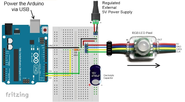
Each LED pixel is individually controllable using two pins on your Arduino. The strand is directional. i.e. There is an INPUT side and an OUTPUT side. The strand should be connected such that wires from the microcontroller are attached to the INPUT side of the first LED pixel. The arrows on each LED show the direction of data flow from INPUT to OUTPUT. The arrow on the first LED pixel should be pointing towards the second LED pixel, NOT towards the breadboard.

Other considerations

As a precaution, you should use a large capacitor across the + and - terminals of the power supply to prevent the initial onrush of current from damaging the RGB LED pixels. I used a 4700uF 16V Electrolytic capacitor for this purpose. According to Adafruit, a 1000uF 6.3V capacitor (or higher) will also do the trick. You may also want to consider a 330 ohm resistor between the Arduino Digital pin and the strand's DATA pin.

If you want to power the Arduino using the regulated 5V external power supply. Disconnect the USB cable from the Arduino, and then connect the positive terminal of the power supply to the 5V pin on the Arduino. Be warned however, that excess voltage at this pin could damage your Arduino, because the 5V regulator will be bypassed.
 
Providing the USB cable is NOT connected to the Arduino, it should now be safe to plug the power supply into the wall. This setup will allow you to power the RGB LED pixel strand and the Arduino using the same power supply.
 
WARNING: Never change any connections while the circuit is powered.

For more information about these RGB LED pixel strands, you may want to visit the Adafruit site. Adafruit was the source for most of these RGB LED pixel Strand precautions.


Fritzing diagram

The following diagram demonstrates how to connect the RGB LED pixel Strand to the Arduino and to the External 5V power supply.


This diagram was created using Fritzing


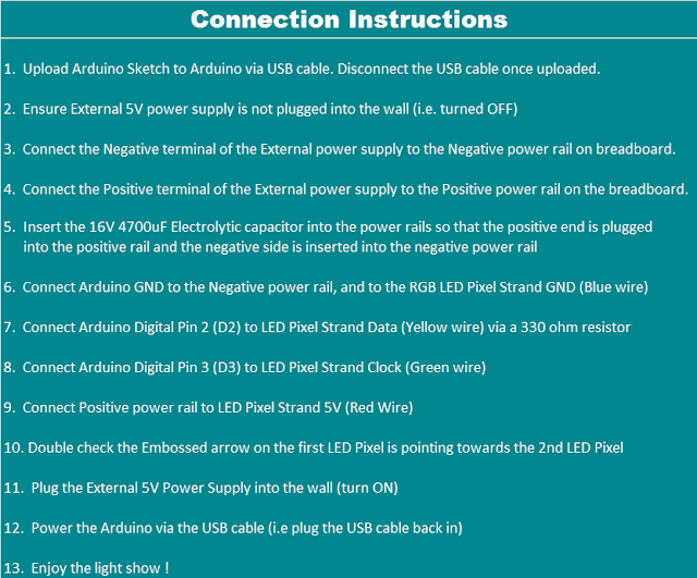
Connection Instructions

These instructions will help to guide you through the process of connecting your RGB LED pixel strand to the Arduino, and to the external power supply. The instructions assume that you will be powering the Arduino via a USB cable.


LightBox assembly

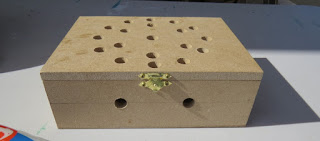
You will need to drill a 12mm hole into the craft timber box for each LED on the strand. It is worth taking the time to make accurate measurements before drilling the holes.
 
I made 12 holes for the outside circle pattern (12cm diameter), 6 holes for the inside circle pattern (8cm diameter), and a hole in the centre. I also made two holes at the front of the box, two on the left side, and two on the right side. I made one last hole at the back of the box for the 2.1mm DC power line socket.
 
Therefore you should have a total of 26 holes in the box. 25 of the holes are for the RGB LED pixel LEDs and one for the external power supply socket.

The lid of the box is about 19.5cm x 14.5cm long, which makes for a very tight squeeze. Probably too tight, because you have to account for the inner dimensions of the box. The inside of the box is used to house the Arduino, breadboard, the chipset side of the LEDs and cables/components. The inner dimensions of the box are 18cm x 13cm. Therefore, the housing for the LED chipset PCB (1.8cm x 2.5cm) prevented the box from closing. I used a Dremel to carve out the space required to close the lid.

Each LED is approximately 8cm apart on the strand, however, if you are really keen, you could cut the wires and extend them to any distance you require. But keep in mind that each LED is mounted on a small PCB (with a WS2801 chipset).You will therefore need to leave a minimum of 2cm between each 12mm hole to accomodate the size of the PCB+LED. If you plan carefully, you can probably squeeze a couple of LEDs within a distance of 1cm... but I would recommend that you give yourself a bit more room, because the PCBs are not square, and there is a good chance that you will have to start all over again.

In hindsight, I could have made the circle patterns a bit smaller, however I don't know if I could have packed these LEDs any closer. The diameter of the inner circle pattern must be at least 2cm smaller than the outer circle pattern. So I think "a bigger box" would have been the best option.

Once all of the holes have been drilled, paint and decorate the box to suit your style.

When the paint is dry, insert the LEDs into the drilled holes in number order.
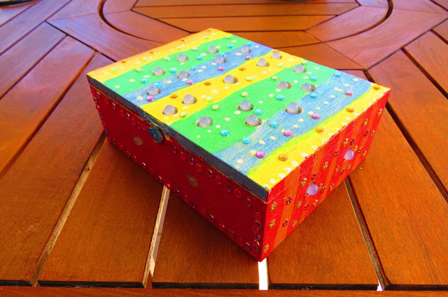
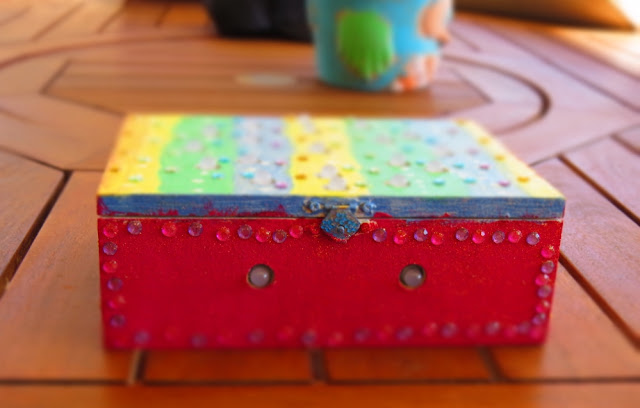
You can see the end result below.


Project Pictures

These pictures show the Light box after it has been drilled and painted. The LEDs have been inserted into their respective holes, and all wires + Arduino + breadboard are hidden within the box.


Concluding comments

Once you start writing LED animations for the RGB LED pixel Lightbox, it is very hard to stop. The colour combinations


If you like this page, please do me a favour and show your appreciation :

 
Visit my ArduinoBasics Google + page.
Follow me on Twitter by looking for ScottC @ArduinoBasics.
I can also be found on Pinterest and Instagram.
Have a look at my videos on my YouTube channel.


This project would not have been possible without OpenLab's collaborative effort.
Please visit their site for more cool projects.


However, if you do not have a google profile...
Feel free to share this page with your friends in any way you see fit.

Arduino LED Light Box

Description

Long straight lines of LED luminescence is nice, but sometimes you may want to light up something that has an unusual shape, or is not so linear. This is where the 12mm diffused flat digital RGB LED Pixels can come into play. This cool strand of 25 NeoPixels fit nicely into 12mm pre-drilled holes of any material you like.

This tutorial is dedicated to making a LED Light Box. I wanted the box to be equally as interesting during the day as it was at night. If you decide you make your own, feel free to be as creative as you want !! However, if you lack artistic acumen, you may need to source a minion or two.


Arduino Libraries and IDE

Before you start to hook up any components, upload the following sketch to the Arduino microcontroller. I am assuming that you already have the Arduino IDE installed on your computer. If not, the IDE can be downloaded from here.

The FastLED library is useful for simplifying the code for programming the NeoPixels. The latest "FastLED library" can be downloaded from here. I used FastLED library version 3.0.3 in this project.

If you have a different LED strip or your NeoPixels have a different chipset, make sure to change the relevant lines of code to accomodate your hardware. I would suggest you try out a few of the FastLED library examples before using the code below, so that you become more familiar with the library, and will be better equipped to make the necessary changes.

If you have a single strand of 25 Neopixels with the WS8201 chipset, then you will not have to make any modification below.


ARDUINO CODE:

Arduino Code Description

The code above will generate a randomised raindrop pattern on the NeoPixel LED Light box, however I have written code for a few more LED animations. These animations were written specifically for this light-box setup. In other words, once you have hooked everything up, you will be able to upload these other LED animations to the Arduino board without any further modification to the hardware/wiring, and yet experience a totally different light effect. You can find the code for the other animation effects by clicking on the links below:

  1. Breathing effect
  2. Ripple effect
  3. Clock effect
  4. Rotation effect
  5. Sweep effect
  6. Spiral effect
  7. Lightning effect
  8. Paparazzi in the Rain effect

Hooking it up:

Power requirements

Each Neopixel LED can draw up to 60 milliamps at maximum brightness (white). ie. 20 mA for each colour (red, green and blue). Therefore you should not try to power the LED strand directly from the Arduino, because the strand will draw too much current and damage the microcontroller(and possibly your USB port too). The LED strand will therefore need to be powered by a separate power supply. The power supply must supply the correct voltage (5V DC) and must also be able to supply sufficient current (1.5A or greater per strand of 25 LEDs).

Excessive voltage will damage or destroy your Neopixel strand. The LEDs will only draw as much current as they need, however your power supply must provide at least 1.5A or greater for each strand. If you chain two strands together, you will need a 5V 3A power supply.

Neopixel strand connection

There are 25 Neopixel LEDs per strand. Four of the wires at each end of the strand are terminated with a JST connector. The red wire is for power (VCC), blue wire for ground (GND), yellow wire is for Data, and green wire for Clock. A spare red wire (VCC) and a spare blue wire (GND) are attached to the ends of each strand for convenience, however, I did not use either. Please double check the colour of your wires... they may be different.

If you want to attach the LED strand to a breadboard, you can cut the JST connector off and use the Neopixel strand wires. Alternatively, if you would prefer to preserve the JST connector, you can simply insert jumper wires (or some male header pins) into the JST connector, and then plug them into the breadboard as required.

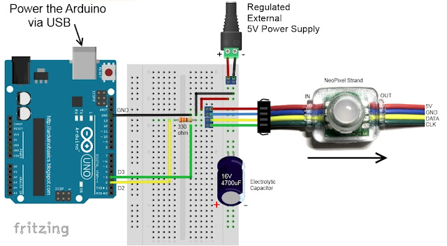
Each neopixel LED is individually controllable using two pins on your Arduino. The strand is directional. i.e. There is an INPUT side and an OUTPUT side. The strand should be connected such that wires from the microcontroller are attached to the INPUT side of the first neopixel. The arrows on each LED show the direction of data flow from INPUT to OUTPUT. The arrow on the first NeoPixel should be pointing towards the second NeoPixel, NOT towards the breadboard.

Other considerations

As a precaution, you should use a large capacitor across the + and - terminals of the power supply to prevent the initial onrush of current from damaging the Neopixels. I used a 4700uF 16V Electrolytic capacitor for this purpose. According to Adafruit, a 1000uF 6.3V capacitor (or higher) will also do the trick. You may also want to consider a 330 ohm resistor between the Arduino Digital pin and the strand's DATA pin.

If you want to power the Arduino using the regulated 5V external power supply. Disconnect the USB cable from the Arduino, and then connect the positive terminal of the power supply to the 5V pin on the Arduino. Be warned however, that excess voltage at this pin could damage your Arduino, because the 5V regulator will be bypassed.
 
Providing the USB cable is NOT connected to the Arduino, it should now be safe to plug the power supply into the wall. This setup will allow you to power the Neopixel strand and the Arduino using the same power supply.
 
WARNING: Never change any connections while the circuit is powered.

For more information about these NeoPixel strands, you may want to visit the Adafruit site. Adafruit was the source for most of these NeoPixel Strand precautions.


Fritzing diagram

The following diagram demonstrates how to connect the NeoPixel Strand to the Arduino and to the External 5V power supply.


This diagram was created using Fritzing


Connection Instructions

These instructions will help to guide you through the process of connecting your NeoPixel strand to the Arduino, and to the external power supply. The instructions assume that you will be powering the Arduino via a USB cable.


LightBox assembly

You will need to drill a 12mm hole into the craft timber box for each LED on the strand. It is worth taking the time to make accurate measurements before drilling the holes.
 
I made 12 holes for the outside circle pattern (12cm diameter), 6 holes for the inside circle pattern (8cm diameter), and a hole in the centre. I also made two holes at the front of the box, two on the left side, and two on the right side. I made one last hole at the back of the box for the 2.1mm DC power line socket.
 
Therefore you should have a total of 26 holes in the box. 25 of the holes are for the Neopixel LEDs and one for the external power supply socket.

The lid of the box is about 19.5cm x 14.5cm long, which makes for a very tight squeeze. Probably too tight, because you have to account for the inner dimensions of the box. The inside of the box is used to house the Arduino, breadboard, the chipset side of the LEDs and cables/components. The inner dimensions of the box are 18cm x 13cm. Therefore, the housing for the LED chipset PCB (1.8cm x 2.5cm) prevented the box from closing. I used a Dremel to carve out the space required to close the lid.

Each LED is approximately 8cm apart on the strand, however, if you are really keen, you could cut the wires and extend them to any distance you require. But keep in mind that each LED is mounted on a small PCB (with a WS2801 chipset).You will therefore need to leave a minimum of 2cm between each 12mm hole to accomodate the size of the PCB+LED. If you plan carefully, you can probably squeeze a couple of LEDs within a distance of 1cm... but I would recommend that you give yourself a bit more room, because the PCBs are not square, and there is a good chance that you will have to start all over again.

In hindsight, I could have made the circle patterns a bit smaller, however I don't know if I could have packed these LEDs any closer. The diameter of the inner circle pattern must be at least 2cm smaller than the outer circle pattern. So I think "a bigger box" would have been the best option.

Once all of the holes have been drilled, paint and decorate the box to suit your style.

When the paint is dry, insert the LEDs into the drilled holes in number order.
You can see the end result below.


Project Pictures

These pictures show the Light box after it has been drilled and painted. The LEDs have been inserted into their respective holes, and all wires + Arduino + breadboard are hidden within the box.


Concluding comments

Once you start writing LED animations for the NeoPixel Lightbox, it is very hard to stop. The colour combinations


If you like this page, please do me a favour and show your appreciation :

 
Visit my ArduinoBasics Google + page.
Follow me on Twitter by looking for ScottC @ArduinoBasics.
I can also be found on Pinterest and Instagram.
Have a look at my videos on my YouTube channel.


This project would not have been possible without OpenLab's collaborative effort.
Please visit their site for more cool projects.


However, if you do not have a google profile...
Feel free to share this page with your friends in any way you see fit.
Captain Hermano’s Mystery Box is Full of Puzzles

[Raffi] needed a birthday present idea but he wanted to do something extra special. He realized that a big part of gift giving is the anticipation and excitement of opening the present. In order to prolong this experience, [Raffi] built an electronic puzzle box. The box contains the final gift, but first a series of puzzles must be solved in order to open the box.

The project runs on an Arduino Mega. This is hooked up to several sensors, including a temperature sensor, GPS unit, and CO sensor. There is also an LCD screen and numeric keypad for user input and output. The project page contains a flow chart that shows all of the puzzles and their solutions. One of the more interesting puzzles requires the user to blow tobacco smoke into a tube. The CO sensor detects the smoke and unlocks the next puzzle.

Some of the puzzles require interacting with outside systems. For example, one puzzle requires the user to send an email to the fictional Captain Hermano’s email address. If the correct keyword is included in the email, the user will receive a reply with the code to enter into the box. Another puzzle requires the user to call a particular phone number and listen for another riddle. We’ve included the video demonstration below.

This isn’t the first puzzle box we’ve seen, but each one has its own special flair. This one is very well made and looks like a lot of care was put into it. We’ve seen another that uses only discrete components. We’ve seen yet another that uses Morse code.

[Thanks Simon]


Filed under: Arduino Hacks
Hack a Day 28 Dec 18:01

Project Review – Silicon Chip Capacitance Substitution Box

Introduction

Every month Australian electronics magazine Silicon Chip publishes a variety of projects, and in some cases various (well … one of two) electronics retailers will pick up the project and offer it as a kit. However for an increasing number of new projects they don’t, which leaves the interested reader with one option – build the entire project from scratch.

But thankfully this is no longer the case – as the team from Silicon Chip now offer a range of project PCBs and matching front panels for sale directly from their website. Although buying these parts is not the cheapest option, it gives the busy person who likes making things a quick start – or the inexperienced more opportunities to complete a successful project.

So as a test of this new service, I bought the PCB and front panel for the Capacitance Substitution Box project described by Nicholas Vinen in the Juily 2012 issue of SC:

This is something I’ve meant to make for a while – but didn’t really have the inclination to make one from scratch, so it was neat to see a version published in the magazine. I believe the subjects in the magazine article are oftern prototypes, which explains the difference in colour for the front panel.

The parts arrived in a week after placing the order, and are of a high quality:

When complete, the capacitance substitution box PCB and panel will fit nicely into an Altronics H0151 enclosure, so you don’t need to do any drilling or filing. The next task was to organise the required parts. The rotary switches, terminal posts and the usual odds and ends can be found at Altronics, Jaycar or other suppliers. However the main components – the capacitors – offered two options.

The first option is to simply use capacitors from personal stock or the stores. However the tolerance of these parts can vary wildly, with up to twenty percent either way. This is ok for simple uses, however when values are combined – the tolerance of larger values can negate the lower values completely. So instead I’ve chosen the second option – which involves using brand-name low-tolerance capacitors.

Thus I turned to element14 who stock not only a huge range of not only regular but also the low-tolerance capacitors, and can also have them on my desk usually by the next working day. Finally, it’s nice to have all the parts arrive in little bags… neatly organised ready to go:

It’s easy to search for low-tolerance parts with element14, as the automatic filtering has tolerance as a parameter:

Furthermore you can also ensure you have the voltage rating of at least 50V DC as well. So after half an hour the capacitor order was completed and arrived when expected – using parts from Panasonic, Vishay, and Wima. The tolerances of our capacitors used varied between one and ten percent, which will help improve the accuracy of the substitution box.

Assembly

The PCB has the capacitor values labelled neatly on the silk-screen, so soldering in all the capacitors was a relatively simple but long operation. Having them arrive in separate packets made life a lot easier. During the soldering process it’s a good idea to have a  break or two, which helps you avoid fatigue and making any mistakes.

There may be a few capacitors that are a little too wide to fit with the others, so they can be mounted on the other side of the PCB:

However they all end up fitting well:

The next step was to configure the first rotary switch for six position use, then cut the plastic stopped from the side of each rotary switch. In the following image you have a before and after example:

Now the rotary switches can have their shafts trimmed and then be soldered onto the PCB:

However ensure you have the first rotary switch in the right way – that is the selections are selected across the top half, not the bottom. Remove the nuts from the rotary switches, and double-check all the capacitors are fitted, as once the next step is completed … going back will be difficult to say the least.

At this point the banana sockets can be fitted to the panel, and then soldered into place, and then you’re finished. Just place the panel/PCB combination inside the box and screw it down:

Using the Capacitance Substitution Box

Does it work? Yes – however you don’t get exact values, there will always be a tolerance due to the original tolerance of the capacitors used and the stray capacitance of the wires between the box and the circuit (or capacitance meter). Nevertheless our example was quite successful. You can see the box in action with our Altronics LC meter kit in this video.

Again, using the best tolerance capacitors you can afford will increase the accuracy of this project.

Conclusion

Over time this would be a useful piece of equipment to have – so if your experiments or projects require varying capacitor value, this project will serve the purpose nicely. Plus it helps with mental arithmetic and measures of capacitance! Please do not ask me for copies of the entire Silicon Chip article, refusal may offend. Instead – visit their website for a reprint or digital access.

And if you enjoyed this article, or want to introduce someone else to the interesting world of Arduino – check out my book (now in a third printing!) “Arduino Workshop”.

Have fun and keep checking into tronixstuff.com. Why not follow things on twitterGoogle+, subscribe  for email updates or RSS using the links on the right-hand column, or join our forum – dedicated to the projects and related items on this website. Sign up – it’s free, helpful to each other –  and we can all learn something.

The post Project Review – Silicon Chip Capacitance Substitution Box appeared first on tronixstuff.

Live your life like there's no tomorrow with David Lee Roth in a box (video)

Seriously, guys, when was the last time you ran with the devil? It's been a while, hasn't it? Leave it to David Lee Roth to show us all the way, yet again, this time courtesy of Arduino-based soundbox created with help from the Adafruit Wave Shield. The box runs on a nine-volt battery and has a big trigger button on the top that plays what sounds like Roth's infamous "Runnin' With the Devil" isolated vocal tracks through a speaker on the bottom. The box's builder has promised more to come -- we'd like to request a Murry Wilson "I'm a genius, too" box, if one isn't already in the pipeline.

Continue reading Live your life like there's no tomorrow with David Lee Roth in a box (video)

Live your life like there's no tomorrow with David Lee Roth in a box (video) originally appeared on Engadget on Thu, 22 Mar 2012 15:44:00 EST. Please see our terms for use of feeds.

Permalink | Email this | Comments