Posts with «precision» label

Project Review – Silicon Chip Capacitance Substitution Box

Introduction

Every month Australian electronics magazine Silicon Chip publishes a variety of projects, and in some cases various (well … one of two) electronics retailers will pick up the project and offer it as a kit. However for an increasing number of new projects they don’t, which leaves the interested reader with one option – build the entire project from scratch.

But thankfully this is no longer the case – as the team from Silicon Chip now offer a range of project PCBs and matching front panels for sale directly from their website. Although buying these parts is not the cheapest option, it gives the busy person who likes making things a quick start – or the inexperienced more opportunities to complete a successful project.

So as a test of this new service, I bought the PCB and front panel for the Capacitance Substitution Box project described by Nicholas Vinen in the Juily 2012 issue of SC:

This is something I’ve meant to make for a while – but didn’t really have the inclination to make one from scratch, so it was neat to see a version published in the magazine. I believe the subjects in the magazine article are oftern prototypes, which explains the difference in colour for the front panel.

The parts arrived in a week after placing the order, and are of a high quality:

When complete, the capacitance substitution box PCB and panel will fit nicely into an Altronics H0151 enclosure, so you don’t need to do any drilling or filing. The next task was to organise the required parts. The rotary switches, terminal posts and the usual odds and ends can be found at Altronics, Jaycar or other suppliers. However the main components – the capacitors – offered two options.

The first option is to simply use capacitors from personal stock or the stores. However the tolerance of these parts can vary wildly, with up to twenty percent either way. This is ok for simple uses, however when values are combined – the tolerance of larger values can negate the lower values completely. So instead I’ve chosen the second option – which involves using brand-name low-tolerance capacitors.

Thus I turned to element14 who stock not only a huge range of not only regular but also the low-tolerance capacitors, and can also have them on my desk usually by the next working day. Finally, it’s nice to have all the parts arrive in little bags… neatly organised ready to go:

It’s easy to search for low-tolerance parts with element14, as the automatic filtering has tolerance as a parameter:

Furthermore you can also ensure you have the voltage rating of at least 50V DC as well. So after half an hour the capacitor order was completed and arrived when expected – using parts from Panasonic, Vishay, and Wima. The tolerances of our capacitors used varied between one and ten percent, which will help improve the accuracy of the substitution box.

Assembly

The PCB has the capacitor values labelled neatly on the silk-screen, so soldering in all the capacitors was a relatively simple but long operation. Having them arrive in separate packets made life a lot easier. During the soldering process it’s a good idea to have a  break or two, which helps you avoid fatigue and making any mistakes.

There may be a few capacitors that are a little too wide to fit with the others, so they can be mounted on the other side of the PCB:

However they all end up fitting well:

The next step was to configure the first rotary switch for six position use, then cut the plastic stopped from the side of each rotary switch. In the following image you have a before and after example:

Now the rotary switches can have their shafts trimmed and then be soldered onto the PCB:

However ensure you have the first rotary switch in the right way – that is the selections are selected across the top half, not the bottom. Remove the nuts from the rotary switches, and double-check all the capacitors are fitted, as once the next step is completed … going back will be difficult to say the least.

At this point the banana sockets can be fitted to the panel, and then soldered into place, and then you’re finished. Just place the panel/PCB combination inside the box and screw it down:

Using the Capacitance Substitution Box

Does it work? Yes – however you don’t get exact values, there will always be a tolerance due to the original tolerance of the capacitors used and the stray capacitance of the wires between the box and the circuit (or capacitance meter). Nevertheless our example was quite successful. You can see the box in action with our Altronics LC meter kit in this video.

Again, using the best tolerance capacitors you can afford will increase the accuracy of this project.

Conclusion

Over time this would be a useful piece of equipment to have – so if your experiments or projects require varying capacitor value, this project will serve the purpose nicely. Plus it helps with mental arithmetic and measures of capacitance! Please do not ask me for copies of the entire Silicon Chip article, refusal may offend. Instead – visit their website for a reprint or digital access.

And if you enjoyed this article, or want to introduce someone else to the interesting world of Arduino – check out my book (now in a third printing!) “Arduino Workshop”.

Have fun and keep checking into tronixstuff.com. Why not follow things on twitterGoogle+, subscribe  for email updates or RSS using the links on the right-hand column, or join our forum – dedicated to the projects and related items on this website. Sign up – it’s free, helpful to each other –  and we can all learn something.

The post Project Review – Silicon Chip Capacitance Substitution Box appeared first on tronixstuff.

Simple Arduino Serial Communication

This Tutorial is progressive and will be updated from time to time. The goal is to start from a very basic form of Arduino Serial communication, and progressively add or improve components so that we can ultimately transmit data from one computer to another using an XBee.
Please note: I am not an expert, but am happy to share what I have learned. The Arduino forums are a great place to ask questions, feel free to link to this blog (if required).

Let us begin.


Stage 1: ECHO ECHO                                                                                    


Parts Required:

  • Computer
  • USB cable
  • Arduino UNO (or equivalent)
  • Arduino IDE

The following code will make the Arduino ECHO anything you send to it. Therefore, if you type a 3, the Arduino will send back a 3. If you type a letter F, the Arduino will send back a letter F. 
Enter the following code into your Arduino IDE and upload it to your Arduino.


Arduino Sketch


 1
2
3
4
5
6
7
8
9
10
11
12
13
14
15
16
17
18
19
20
/* Simple Serial ECHO script : Written by ScottC 03/07/2012 */

/* Use a variable called byteRead to temporarily store
the data coming from the computer */
byte byteRead;

void setup() {
// Turn the Serial Protocol ON
Serial.begin(9600);
}

void loop() {
/* check if data has been sent from the computer: */
if (Serial.available()) {
/* read the most recent byte */
byteRead = Serial.read();
/*ECHO the value that was read, back to the serial port. */
Serial.write(byteRead);
}
}
The above code was formatted using this site


Instructions

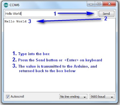
1. Once the Arduino sketch has been uploaded to the Arduino. Open the Serial monitor, which looks like a magnifying glass at the top right section of the Arduino IDE. Please note, that you need to keep the USB connected to the Arduino during this process, as the USB cable is your communication link between your computer and the Arduino.


2. Type anything into the top box of the Serial Monitor and press <Enter> on your keyboard. This will send a series of bytes to the Arduino. The Arduino will respond by sending back your typed message in the larger textbox.


3. Please note that we are using Serial.write(byteRead); on line 18 to get the Arduino to ECHO the message back to you on your computer. 


Things to Try 

1. Delete lines 16 to 18, and replace them with the following line :

               Serial.write(Serial.read());

This essentially eliminates the byteRead variable in the sketch above. But we will be using it later on, so once you have tested it out, put the code back together as originally displayed.


--------------------------------------------------------------------
2. Replace line 18 with a Serial.println instead of Serial.write

               Serial.println(byteRead);

Once uploaded, type 1 <enter> 2 <enter> 3 <enter>  into the Serial Monitor.
You should see:

49
50
51

Serial.print and Serial.println will send back the actual ASCII code, whereas Serial.write will send back the actual text. See ASCII codes for more information.


--------------------------------------------------------------------
3. Try typing in numbers like 1.5  or  2.003  or  -15.6 into the Serial Monitor using Serial.write and Serial.print or Serial.println commands as described before.

You will notice that the decimal point transmits as a number using Serial.print  or Serial.println, and will transmit as a decimal point when using Serial.write


STAGE 2: Delimiters                                                                                


How do you handle 2 or more numbers when sending or receiving?
Let us say that you have number pairs that you want the Arduino to interpret. How do you separate the numbers? The answer is Delimiters.
You may be familiar with CSV (comma separated value) files, where each field is separated by a comma (,). The comma is a useful way of separating or grouping information.

Lets say you have the following stream of numbers:
12345678910

How will your Arduino know if this is a single number, or a series of numbers?
Eg:

12,34,56,78,91,0
123,456,78,910
1,2,3,4,5,6,7,8,9,10
12345678910

The comma delimiters help to identify how the numbers should be interpreted.

 In the echo example in Stage 1 above, you would have noticed that when we used Serial.print(byteRead); that the values displayed one after another in a similar fashion to 12345678910.

You would have also noticed that Serial.println(byteRead); provided a line break between each value sent. And depending on the numbers sent, it could have looked like this:
12
34
56
78
91
0

The Serial.println() function essentially uses a line feed to separate the values being sent. This line break can be used as a delimiter, but we will look at that later on. For now we will concentrate on using a comma (,).

We will now get the Arduino to "listen" for the comma to help it identify a new number.
According to the ASCII code site, a comma is equal to byte code 44. So when the Arduino reads a byte code that is equal to 44, we will get it to print a line feed.


Enter the following sketch into your Arduino IDE and upload it to your Arduino.

Arduino Sketch


 1
2
3
4
5
6
7
8
9
10
11
12
13
14
15
16
17
18
19
20
21
22
23
24
25
26
27
/* Simple Serial ECHO script : Written by ScottC 04/07/2012 */
/* Stage 2 : Delimiters */

/* Use a variable called byteRead to temporarily store
the data coming from the computer */
byte byteRead;

void setup() {
// Turn the Serial Protocol ON
Serial.begin(9600);
}

void loop() {
/* check if data has been sent from the computer: */
if (Serial.available()) {
/* read the most recent byte */
byteRead = Serial.read();

/*Listen for a comma which equals byte code # 44 */
if(byteRead==44){
Serial.println();
}else{
/*ECHO the value that was read, back to the serial port. */
Serial.write(byteRead);
}
}
}
The above code was formatted using this site


Instructions

1. Once the code has been uploaded to the Arduino, open the Serial Monitor once again and type the following sequence of numbers:

1 <enter>  2 <enter> 3 <enter>

You should see the Serial monitor display the following number:    123


--------------------------------------------------------------------
2. While still in the serial monitor, type the following:

, <enter> 1 <enter> , <enter> 2 <enter> , <enter> 3 <enter> ,

Please note the commas between each numerical entry. You should now see a pattern like this:
1
2
3


--------------------------------------------------------------------
3. While still in the serial monitor, type the following:

12,23,34,45, <enter>

Please note the commas between each numerical entry. You should now see a pattern like this:
12
23
34
45

You will notice that the commas have been replaced by line feeds, and each number should display on a new line.


--------------------------------------------------------------------
4. While still in the serial monitor, type the following:

1,,2,,3, <enter>

You should see the following pattern:
1

2

3


So hopefully that explains the concept of delimiters and how they can be used to separate a stream of numbers, no matter how long it takes to get to the Arduino. We used an IF-statement to listen for the comma, but we could have used any other delimiter provided we knew the byte code.

We did not identify how to send delimiters FROM the Arduino, but we will get to that I promise. It is not that hard, and uses a similar principle. I am sure you can work it out, if not, stay tuned.


STAGE 3: Arduino Maths: Simple addition                                                  


In this stage, we are going to get the Arduino to do simple maths. We will send it two integers (or whole numbers), and the Arduino will do the hard work and send us the answer in no time at all.
This might seem like a simple task, but when you send a number like 27 to the Arduino, it does not receive the number 27. It receives 2 and then 7 in byte form. In other words, the Arduino will see the byte codes 50 and then 55 as per the ASCII table on this page.

One way to convert this byte code back to a 2 and a 7 is to subtract 48 from each byte received, providing the byte is in the range 48 to 57 inclusive (which equates to the numbers 0-9).
We are not done yet. We then need to join these numbers to make 27.

Step1: Subtract 48 from the bytes received, only if the bytes are in the range 48 to 57.
                 Example:    50 - 48 = 2
                                    55- 48 = 7

Step2: Multiply the previous number by 10, before adding the most recent byte received.
                 Example:   (2 x 10) + 7 = 27

If we have a number like 1928, then we would create this number using the following calculation
                                   1 =                         1
                   (1 x 10) + 9 =    10 + 9   =   19
                (19 x 10) + 2  = 190 + 2   =  192
              (192 x 10) + 8  = 1920 + 8 = 1928

Step3: Use a "+" sign as a delimiter so that the Arduino can move onto the Second number

Step4:  Capture the second number as per Step2. An "=" sign will tell the Arduino that it has reached the end of the second number, and to proceed to step 5.

Step5:  Add the 2 numbers together and send back the answer.


The following code will carry out the 5 steps above.
Enter the following sketch into your Arduino IDE and upload it to your Arduino.

Arduino Sketch


 1
2
3
4
5
6
7
8
9
10
11
12
13
14
15
16
17
18
19
20
21
22
23
24
25
26
27
28
29
30
31
32
33
34
35
36
37
38
39
40
41
42
43
44
45
46
47
48
49
50
51
52
53
54
55
56
57
58
59
60
61
62
63
64
/* Simple Serial ECHO script : Written by ScottC 05/07/2012 */
/* Stage 3: Arduino Maths: Simple Addition */

/* Global variables needed for programming workflow
byteRead: holds the value being read from the COM port
num1: holds the entire first number
num2: holds the entire second number
answer: holds the sum of num1 and num2
mySwitch: enables the switch between num1 and num2 */

byte byteRead;
long num1, num2,answer;
boolean mySwitch=false;

void setup() {
/* Turn the Serial Protocol ON and
initialise num1 and num2 variables.*/
Serial.begin(9600);
num1=0;
num2=0;
}

void loop() {
/* check if data has been sent from the computer: */
while (Serial.available()) {
/* read the most recent byte */
byteRead = Serial.read();

//listen for numbers between 0-9
if(byteRead>47 && byteRead<58){
//number found

/* If mySwitch is true, then populate the num1 variable
otherwise populate the num2 variable*/
if<!mySwitch)><br /> num1=(num1*10)+(byteRead-48);<br /> }<span>else</span>{<br /> num2=(num2*10)+(byteRead-48);<br /> }<br /> }<br /> <br /> <span>/*Listen for an equal sign (byte code 61) </span><br /><span> to calculate the answer and send it back to the</span><br /><span> serial monitor screen*/</span><br /> <span>if</span>(byteRead==61){<br /> answer=num1+num2;<br /> Serial.print(num1);<br /> Serial.print(<span>"+"</span>);<br /> Serial.print(num2);<br /> Serial.print(<span>"="</span>);<br /> Serial.println(answer);<br /> <br /> <span>/* Reset the variables for the next round */</span><br /> num1=0;<br /> num2=0;<br /> mySwitch=<span>false</span>;<br /> <br /> <span>/* Listen for the addition sign (byte code 43). This is</span><br /><span> used as a delimiter to help define num1 from num2 */</span> <br /> }<span>else</span> <span>if</span> (byteRead==43){<br /> mySwitch=<span>true</span>;<br /> }<br /> }<br />}<br /></pre></td></tr></tbody></table></div><br /><span>The above code was formatted using <a href="http://hilite.me/">this site</a></span><br /><br /><br /><h3> <u>Instructions</u></h3><br /><b>1.</b> Once the code has been uploaded to the Arduino, open the Serial Monitor once again and type the following sequence:<br /><br />         <span>1+2=   <enter></span><br /><br />You should get the following message sent back to Serial Monitor<br /><br />        <span> 1+2=3</span><br /><br /><br /><br /><h3> <b><u>Things to Try</u></b></h3><b>1.</b>   Enter this sequence: <br />              <span>10   <enter></span><br /><span>               +   <enter></span><br /><span>              10  <enter></span><br /><span>               =   <enter></span><br /><br />       Result:     <span>10+10=20</span><br /><br /><span>--------------------------------------------------------------------</span><br /><b>2. </b>  Enter this sequence:<br />            <span> 10  <enter></span><br /><span>             20  <enter></span><br /><span>             +5= <enter></span><br /><br /><br />      Result:  <span> 1020+5=1025</span><br /><br /><br /><br /><br /><span>--------------------------------------------------------------------</span><br /><b>3.</b>   Enter this sequence:<br />            <span> 10+20+30=   <enter></span><br /><br /><br />      Result:    <span>10+2030=2040</span><br /><br />I have specifically written this script to add <b>two</b> whole numbers together. If you start to introduce more complicated calculations, the results become unpredictable.<br /><br /><span>--------------------------------------------------------------------</span><br /><b>4.</b>    Enter this sequence:<br />           <span>1.2+1.0=    <enter></span><br /><br />      Result: <span>12+10=22</span><br /><br />Once again, I have only designed this script to handle whole numbers. Therefore, decimal points are ignored.<br /><br /><span>--------------------------------------------------------------------</span><br /><b>5.</b>  Enter this sequence:<br />         <span> -5 + 10=     <enter></span><br /><br /><br />     Result:    <span>5+10=15</span><br /><br /><br />This script ignores the negative sign, and treats the -5 as a positive 5.<br /><br /><br /><div>I have done this on purpose. I wanted to show you how the Arduino reads numbers from the com port, and how easy it is to exclude vital functionality in your code. I have kept this script simple, however, if you wanted to, you could make the Arduino deal with each of the above situations and more.  Multiplication, division and subtraction is handled in the same way. </div><br />This is the last thing I want you to try before we go to the next stage:<br /><br />6. Enter this sequence:<br />           <span>2147483646+1=  <enter></span>           Result:  <span>2147483646+1=2147483647</span><br />          <span> 2147483647+1=  <enter></span>           Result: <span>2147483647+1=</span><span>-</span><span>2147483648</span><br /><br /><br />Note that the maximum size of a "long" number is 2147483647. If you add one to this number, the result is equal to the minimum size of a "long" which is -2147483648.<br /><br /><br /><br /><br /><h3> <b><span><span>STAGE 4:  Sending doubles to Arduino</span> : <span>The double doubler</span>             </span></b></h3><div>Now we get to some tricky business. Sending and receiving Doubles (to and from) the Arduino.<br /><br />Up until now, I have tried to keep it simple using whole numbers, but there will come a time when you will want to send a fraction of a number through the Serial line.</div><div>To test our program, we will want to send a very small number to the Arduino, multiply the number by 2, and return it back.</div><div><br /></div><div>Our final test is to try a number like :  <b>0.000001</b></div><div>             and then a number like:<b>   123.321</b></div><div><br /></div><div><br /><b><span>IMPORTANT NOTE</span></b>:   When the Arduino sends a float or a double through the COM port using Serial.print() or Serial.println(), it will automatically send the number to 2 decimal places.<br />A number like 1.2345 will appear as 1.23,   and a number like 1.9996 will appear as 2.00<br />To demonstrate this, we will get the Arduino to send these floats/doubles to the Serial Monitor.<br /><br /><br /><div>Enter the following sketch into your Arduino IDE and upload it to your Arduino.</div><div><br /></div><h3> <u>Arduino Sketch</u></h3><br /><div><table><tbody><tr><td><pre><span><span> 1<br /> 2<br /> 3<br /> 4<br /> 5<br /> 6<br /> 7<br /> 8<br /> 9<br />10<br />11<br />12<br />13<br />14<br />15<br />16<br />17<br />18<br />19<br />20<br />21<br />22<br />23<br />24<br />25<br />26<br />27<br />28</span></span></pre></td><td><pre><span>/* Stage 4: Simple Transmission of a Double</span><br /><span> Written by ScottC on 7/7/2012 */</span><br /><br /><span>/* Declare the doubles that will be sent to the Serial Monitor */</span><br /> <span>double</span> myDub1, myDub2;<br /><br /><span>/* This part of the program only runs ONCE */</span><br /><br /> <span>void</span> setup(){<br /><br /> <span>/* Turn ON Serial Communication */</span><br /> Serial.begin(9600);<br /> <br /> <span>/* Assign a value 1.2345 and 1.9996 to the Doubles being sent */</span><br /> myDub1=1.2345;<br /> myDub2=1.9996;<br /> <br /> <span>/*Send the values to the Serial Monitor */</span><br /> Serial.print(<span>"myDub1 (1.2345) : "</span>);<br /> Serial.println(myDub1);<br /> Serial.print(<span>"myDub2 (1.9996) : "</span>);<br /> Serial.println(myDub2);<br /> }<br /><br /><br /> <span>void</span> loop(){<br /> <span>//Loop does nothing</span><br /> }<br /></pre></td></tr></tbody></table></div><span>The above code was formatted using </span><a href="http://hilite.me/">this site</a><br /><br />When you open the Serial monitor (after you have uploaded the sketch above), you will notice the following output:<br /><br /><br />         <span> myDub1 (1.2345) :</span> <span>1.23</span><br />         <span> myDub2 (1.9996) :</span> <span>2.00</span><br /><div><br /></div><br /><br />The <span>blue text</span> represents the string (or array of characters) being sent using lines 19 and 21.<br />The <span>red text</span> represents the actual double being sent using lines 20 and 22.<br /><br />You will notice that myDub2 rounds to 2.00.  This may or may not be what you want.<br />If you wish to increase the number of decimal places, then you will need to change lines 20 and 22 to the following:<br /><br /><span><span>20         Serial.println(myDub1,</span><span>4</span><span>)</span>;</span><br /><span><span>22         Serial.println(myDub2,</span><span>4</span><span>);</span></span><br /><br />The number 4 highlighted in red, indicates the number of decimal places you wish to send.<br />Try it ! And try changing this number to something bigger or smaller.<br /><br />---------------------------------------------------------------------------------------------------<br />Ok - now that we understand this little Serial.print(double,decimals) trick, we will now get the Arduino to echo back a Double.<br /><br />Before we jump in, perhaps we should try and map out our strategy. For this we will choose a simple decimal to make it easier. So in this example, we will choose <b>0.1</b></div><div>Once we get this working, we can then do our final test (as mentioned above).</div><div><br /></div><div>If we send 0.1 to the Arduino, it will read the following byte code</div><div><br /></div><div>48                    0</div><div>46                    .</div><div>49                    1</div><div><br /></div><div>We can use the decimal point as a delimiter.<br />We will use the following 5 steps to echo the double back to the Serial Monitor:</div><div><br /></div><div><b><span>Step1</span>:</b> Arduino collects all numbers before the decimal point using the same technique as in Stage3.<br /><br /></div><div><b><span>Step2</span>: </b>When the Arduino receives byte code 46, it will go into decimal mode.<br /><br /></div><div><b><span>Step3</span>:</b> The Arduino will collect numbers after the decimal point using a similar technique to step1.<br /><br /></div><div><b><span>Step4</span>:</b> Use maths to create the double, and then multiply it by 2<br /><br /></div><div><b><span>Step5</span>:</b> Display the doubled Double value in the Serial monitor.</div><div><br /></div><div><br /></div><div><br /><div>Enter the following sketch into your Arduino IDE and upload it to your Arduino.</div><div><br /></div><h3> <u>Arduino Sketch</u></h3></div><div><br /></div><div><table><tbody><tr><td><pre><span><span> 1<br /> 2<br /> 3<br /> 4<br /> 5<br /> 6<br /> 7<br /> 8<br /> 9<br />10<br />11<br />12<br />13<br />14<br />15<br />16<br />17<br />18<br />19<br />20<br />21<br />22<br />23<br />24<br />25<br />26<br />27<br />28<br />29<br />30<br />31<br />32<br />33<br />34<br />35<br />36<br />37<br />38<br />39<br />40<br />41<br />42<br />43<br />44<br />45<br />46<br />47<br />48<br />49<br />50<br />51<br />52<br />53<br />54<br />55<br />56<br />57<br />58<br />59<br />60<br />61<br />62<br />63<br />64<br />65<br />66<br />67<br />68<br />69<br />70<br />71<br />72<br />73<br />74<br />75<br />76<br />77<br />78<br />79<br />80<br />81<br />82<br />83<br />84<br />85</span></span></pre></td><td><pre><span>/* Simple Serial ECHO script : Written by ScottC 06/07/2012 */</span><br /><span>/* Stage 4: Double doubler */</span><br /><br /><span>/* Global variables needed for programming workflow</span><br /><span> ------------------------------------------------------</span><br /><span> byteRead: holds the value being read from the COM port</span><br /><span> num1: holds the number before the decimal point</span><br /><span> num2: holds the number after the decimal point</span><br /><span> complNum: holds the complete number (before multiplation)</span><br /><span> answer: holds the final value after multiplication</span><br /><span> counter: is used to convert num2 to the number after the decimal</span><br /><span> numOfDec: counts the numbers after the decimal point</span><br /><span> mySwitch: enables the switch between num1 and num2 */</span><br /> <br /> byte byteRead;<br /> <span>double</span> num1, num2;<br /> <span>double</span> complNum,answer,counter;<br /> <span>int</span> numOfDec;<br /> boolean mySwitch=<span>false</span>;<br /><br /><br /> <span>void</span> setup() { <br /><span>/* Turn the Serial Protocol ON and </span><br /><span> initialise num1 and num2 variables.*/</span><br /> Serial.begin(9600);<br /> num1=0;<br /> num2=0;<br /> complNum=0;<br /> counter=1;<br /> numOfDec=0;<br /> }<br /><br /> <span>void</span> loop() {<br /><span>/* check if data has been sent from the computer: */</span><br /> <span>while</span> (Serial.available()) {<br /> <span>/* read the most recent byte */</span><br /> byteRead = Serial.read();<br /> <br /> <span>//listen for numbers between 0-9</span><br /> <span>if</span>(byteRead>47 && byteRead<58){<br /> <span>//number found</span><br /> <br /> <span>/* If mySwitch is true, then populate the num1 variable</span><br /><span> otherwise populate the num2 variable*/</span><br /> <span>if</span><!mySwitch)><br /> num1=(num1*10)+(byteRead-48);<br /> }<span>else</span>{<br /> num2=(num2*10)+(byteRead-48);<br /> <br /> <span>/* These counters are important */</span><br /> counter=counter*10;<br /> numOfDec++;<br /> }<br /> }<br /> <br /> <span>/*Listen for an equal sign (byte code 61) </span><br /><span> to calculate the answer and send it back to the</span><br /><span> serial monitor screen*/</span><br /> <span>if</span>(byteRead==61){<br /> <span>/* Create the double from num1 and num2 */</span><br /> complNum=num1+(num2/(counter));<br /> <br /> <span>/* Multiply the double by 2 */</span> <br /> answer=complNum*2;<br /> <br /> <span>/* Send the result to the Serial Monitor */</span> <br /> Serial.print(complNum,numOfDec);<br /> Serial.print(<span>" x 2 = "</span>);<br /> Serial.println(answer,numOfDec);<br /> <br /> <span>/* Reset the variables for the next round */</span><br /> num1=0;<br /> num2=0;<br /> complNum=0;<br /> counter=1;<br /> mySwitch=<span>false</span>;<br /> numOfDec=0;<br /> <br /> <span>/* Listen for the decimal point (byte code 46). This is</span><br /><span> used as a delimiter to help define num1 from num2 */</span> <br /> }<span>else</span> <span>if</span> (byteRead==46){<br /> mySwitch=<span>true</span>;<br /> }<br /> }<br /> }<br /></pre></td></tr></tbody></table></div><div><span>The above code was formatted using </span><a href="http://hilite.me/">this site</a></div><div><br /></div><div><br /></div><div><br /><h3> <b><u>Things to Try</u></b></h3><div><b><u><br /></u></b></div><div>1. Type the following into the serial monitor:</div><div><br /></div><div>       <span>1.2=  <enter></span>                             Result:   <span>1.2 x 2 = 2.4</span></div><div><br /></div><div>Make sure that you type the equal sign (=) before you press enter, otherwise the Arduino will not know that you are finished, and will not send anything back.</div><div><br /></div><div>--------------------------------------------------------------------</div><div>2. Type the following into the serial monitor:</div><div><br /></div><div>      <span>100.001=  <enter></span>                      Result:   <span>100.001 x 2 = 200.002</span></div><div><br /></div><div>You will notice that the Arduino is formatting the decimal to the SAME number of decimals as that entered.</div><div>This is controlled by the variable: <span>numOfDec</span>.</div><div>---------------------------------------------------------------------</div><div>3. Now for our final test: Type the following into the serial monitor:</div><div><br /></div><div>   <span> 0.000001= <enter></span>                       Result: <span>0.000001 x 2 = 0.000002</span></div><div><br /></div><div>First test:<span> PASSED</span></div><div><br /></div><div>----------------------------------------------------------------------</div><div>4. Type the following into the Serial monitor for our last test:</div><div><br /></div><div>     <span>123.321=  <enter></span>                      Result: <span>123.321 x 2 = 246.642</span></div><div><br /></div><div>Second test: <span>PASSED</span></div><div>-----------------------------------------------------------------------</div><div><br /></div><div><span>BEWARE</span>: While everything looks perfect, let me tell you that it isn't. But hopefully this code will help you get on the right track. If you decide to type in a number like 123123.111222, you will not get the answer you expected. </div><div>I have found that this program will work if the amount of numbers before and after the decimal point are less than about 9.  Eg. 1234.1234   will produce the right result.</div><div>However, 11111.2222 will NOT, because there are 9 numbers represented.</div><div><br /></div><div>I think this has something to do with the memory allocated to a double, but I am not sure. </div><div>I don't know if people work with these types of numbers, but I am sure there is a workaround, and I am sure someone out there can work it out. I don't personally need this kind of precision, but thought to mention it just in case you do.</div><div><br /></div><div><br />----------------------------------------------------------------------- <br />----------------------------------------------------------------------- <br /><br /><h3> <b><span><span>STAGE 5:  Sending sensor data to the Serial Monitor</span>             </span></b></h3><br /><br />We know the Arduino is very good at copy-Cat games, how about getting the Arduino to send us some data from one of our sensors. We will use the Serial Monitor to view the sensor data.<br /><br />Disconnect the USB cable, and hook up one of your favourite analog sensors to your Arduino. For simplicity, I am going to hook up a potentiometer as per the Fritzing sketch below.<br /><br /><h3> <u> Parts Required</u></h3><br /><ul><li>Arduino UNO (or equivalent)</li><li>Computer with USB cable</li><li>Breadboard</li><li>Potentiometer</li><li>3 Wires</li></ul><div><br /></div><br /><h3> <u> Arduino Fritzing Sketch</u></h3><br /></div><div><div><a href="http://1.bp.blogspot.com/-JZlWUi3MDck/T_g6ldkqSVI/AAAAAAAAAPY/_UJj4EU3YYE/s1600/Fritzing_Potentiometer_Sketch.jpg"><img src="http://1.bp.blogspot.com/-JZlWUi3MDck/T_g6ldkqSVI/AAAAAAAAAPY/_UJj4EU3YYE/s400/Fritzing_Potentiometer_Sketch.jpg" /></a></div><br /></div><div><br /></div><div>     </div><div><br /></div><div><br /></div></div><br /><br /><br /><br /><br /><br /><br /><br /><br /><br /><br /><br /><br /><br /><br /><br /><br />Once you have attached your sensor to the board, plug your USB cable into the Arduino, and upload the following sketch.<br /><br /><br /><h3> <u>Arduino Sketch</u></h3><div><u><br /></u></div><div><table><tbody><tr><td><pre><span><span> 1<br /> 2<br /> 3<br /> 4<br /> 5<br /> 6<br /> 7<br /> 8<br /> 9<br />10<br />11<br />12<br />13<br />14<br />15<br />16<br />17<br />18<br />19<br />20<br />21</span></span></pre></td><td><pre> <span>/* Stage 5: Send Sensor Value to Serial Monitor</span><br /><span> Written by ScottC on 7/7/2012 */</span><br /><br /> <span>int</span> sensorVal = 0; <br /><br /> <span>void</span> setup() {<br /> <span>// Setup Serial communication with computer</span><br /> Serial.begin(9600);<br /> }<br /><br /> <span>void</span> loop() {<br /> <span>// Read the value from the sensor:</span><br /> sensorVal = analogRead(A0);<br /> <br /> <span>// Send the value to the Serial Monitor</span><br /> Serial.print(<span>"Sensor Value="</span>);<br /> Serial.println(sensorVal);<br /><br /> <span>// Interval between readings = 1 second</span><br /> delay(1000); <br /> }<br /></pre></td></tr></tbody></table></div><div><span>The above code was formatted using </span><a href="http://hilite.me/">this site</a><br /><u><br /></u><br /><u><br /></u><br /><h3> <u>Instructions</u></h3></div></div></div><div>1. Open the Serial monitor and watch the readings change depending on the input conditions. In my case, by turning the potentiometer from left to right, I get an output similar to the picture below.</div><div><br /></div><div><a href="http://2.bp.blogspot.com/-F8H8h8YkXJo/T_g_dcPTN1I/AAAAAAAAAPk/AXQaR5x_UFk/s1600/Serial+Monitor.jpg"><img src="http://2.bp.blogspot.com/-F8H8h8YkXJo/T_g_dcPTN1I/AAAAAAAAAPk/AXQaR5x_UFk/s400/Serial+Monitor.jpg" /></a></div><div><br /></div><div><br /></div><div><br /></div><div><br /></div><div><br /></div><div><br /></div><div><br /></div><div><br /></div><div><br /></div><div><br /></div><div><br /></div><div><br /></div><div><br /></div><div><br /></div><div><br /></div><div><br /></div><div><br /></div><div><br /></div><div><br /></div><div>As per the Arduino reference site, <a href="http://arduino.cc/en/Reference/analogRead">AnalogRead</a> returns an integer between 0 and 1023. You can see this is true based on the picture above. But what if we do not want a value between 0 and 1023. Let us say we want a value between 0 and 100?</div><div><br /></div><div>You would have to use the <a href="http://arduino.cc/en/Reference/Map">map function</a>. We will do it by changing line 13 to this:</div><div><br /></div><div><pre><span><span>13</span></span><span> </span><span><span><b>sensorVal = map(analogRead(A0),0,1023,0,100);</b></span></span></pre></div><div><br /></div><div>The map function is quite a cool function, and good fun to play around with. So here are some things to try.</div><div><h3> <b><u>Things to Try</u></b></h3></div><div>1. Change line 13 to the following, upload to the Arduino </div><div>    and then open the Serial Monitor to see the effect.</div><div><br /></div><div><b><span>Trial 1</span></b>:</div><div><pre><span><span>13</span></span><span> </span><span><span><b>sensorVal = map(analogRead(A0),0,1023,100,0);</b></span></span></pre></div><div><br /></div><div><div><b><span>Trial 2</span></b>:</div><div><pre><span><span>13</span></span><span> </span><span><span><b>sensorVal = map(analogRead(A0),0,1023,0,1000);</b></span></span></pre></div></div><div><br /></div><div><div><span><b>Trial 3</b></span>:</div><div><pre><span><span>13</span></span><span> </span><span><span><b>sensorVal = map(analogRead(A0),200,800,0,100);</b></span></span></pre></div></div><div><br /></div><div><br /></div><div>In <b><span>Trial 1</span></b>: We see that the values have been inverted. Instead of ranging from 0 up to100, they now go from 100 down to 0.</div><div><br /></div><div>In <b><span>Trial 2</span></b>: The analog readings are now mapped to a range of 0 up to 1000. </div><div><br /></div><div>In <b><span>Trial 3</span></b>: The analog readings that range from 200 to 800 are mapped to a range of 0 to 100. Therefore if the analog readings drop below 200, we will end up with a negative value for sensorVal. </div><div>If the analog readings go above 800, we will end up with a value greater than 100.  For this particular example, my readings actually range from  -33 to 137.</div><div><br /></div><div>Therefore an Analog reading of 0 = -33</div><div>                 Analog reading of 200 = 0</div><div>                 Analog reading of 800 = 100</div><div>               Analog reading of 1023 = 137</div><div><br /></div><div><br /></div><div>----------------------------------------------------------------------------------</div><div>What if we don't want the output to go beyond our intended limits of 0 to 100?</div><div>Then you would have to use the <a href="http://arduino.cc/en/Reference/Constrain">constrain function</a>. This essentially trims the reading range of the sensor, and sets a minimum and maximum value.</div><div><br /></div><div>Replace line 13 with the following code:</div><div><br /></div><div><pre><span><span>13</span></span><span> </span><span><span><b>sensorVal = constrain(map(analogRead(A0),200,800,0,100),0,100);</b></span></span></pre></div><div><br /></div><div><div>Therefore an Analog reading of 0 = 0</div><div>                 Analog reading of 100 = 0</div><div>                 Analog reading of 200 = 0</div><div>                 Analog reading of 800 = 100</div><div>                  Analog reading of 955 = 100</div><div>               Analog reading of 1023 = 100</div></div><div>Analog values between 200 and 800 will produce a result between 0 and 100.</div><div><br /></div><div>-------------------------------------------------------------------------------------<br /><br /><h3><span>If you wish to continue with this tutorial (stage 6 and above), please follow this link:  <a href="http://arduinobasics.blogspot.com/2012/07/arduino-basics-simple-arduino-serial_09.html">Serial Communication Stage 6 and above</a> </span></h3></div><div><br /></div><div><br /></div> <br />  <br />  <div> <p> <!--separator --> <img src="https://images-blogger-opensocial.googleusercontent.com/gadgets/proxy?url=http%3A%2F%2F1.bp.blogspot.com%2F-XQiwNpdqOxk%2FT_rKCzDh4nI%2FAAAAAAAAAQY%2FOfYBljhU6Lk%2Fs1600%2FSeparator.jpg&container=blogger&gadget=a&rewriteMime=image%2F*" /><br /> <br /> </p> </div> <p> <div> <p> If you like this page, please do me a favour and show your appreciation : <br /> <br />  <br /> Visit my <a href="https://plus.google.com/u/0/b/107402020974762902161/107402020974762902161/posts">ArduinoBasics Google + page</a>.<br /> Follow me on Twitter by looking for <a href="https://twitter.com/ArduinoBasics">ScottC @ArduinoBasics</a>.<br /> I can also be found on <a href="https://www.pinterest.com/ArduinoBasics/">Pinterest</a> and <a href="https://instagram.com/arduinobasics">Instagram</a>. <br /> Have a look at my videos on my <a href="https://www.youtube.com/user/ScottCMe/videos">YouTube channel</a>.<br /> </p></div> <div> <p>              <a href="http://arduinobasics.blogspot.com.au/p/arduino-basics-projects-page.html"><img src="http://2.bp.blogspot.com/-4b59S-y-Tws/VYeJtC1HNyI/AAAAAAAABk4/_CWyTKOPYOw/s320/ArduinoBasics_OpenLogo%2Bon%2BBlack.png" /></a> </p></div> <div> <p> <img src="https://images-blogger-opensocial.googleusercontent.com/gadgets/proxy?url=http%3A%2F%2F1.bp.blogspot.com%2F-XQiwNpdqOxk%2FT_rKCzDh4nI%2FAAAAAAAAAQY%2FOfYBljhU6Lk%2Fs1600%2FSeparator.jpg&container=blogger&gadget=a&rewriteMime=image%2F*" /><br /> <br /> </p></div> <div> <p> However, if you do not have a google profile... <br />Feel free to share this page with your friends in any way you see fit. </p></div></p>