Posts with «guest project» label

EasyEDA RGB5050 LED Scroll Bar


Guest Post Disclaimer

This is a guest post by the EasyEDA team. I would like to thank EasyEDA for providing this tutorial for everyone to enjoy. All information within this post was provided by EasyEDA.


Description

None of us could deny the fact that we would love with to play with LED’s and lighting stuff. I love to play with LED’s and create attractive lighting effects. This project was a result of such an attempt where I created a stunning RGB light effect using the popular development platform Arduino Nano. Let’s see the circuit, code and instruction on building this project:


Image source: EasyEDA


Arduino Libraries and IDE

No libraries are required for this project. The Arduino IDE can be downloaded from the Arduino website. Here is the download link.

ARDUINO CODE:


Preparing the LED strips

Cut down the LED strips into 10 single pieces. Make sure you cut them into equal halves and make sure that only the copper conduction plate in the strip is cut. Making a wrong cut disrupts the electrical conductivity between the LED’s. After cutting down into separate strips, you will need to connect each strip using a Dupont wire connectors.

Image source: EasyEDA


Designing the Control Board

I have made a custom control board that incorporates an Arduino Nano. The control board is used to boost the incoming signal from Arduino and lights up the corresponding LED strips.


Image source: EasyEDA


Control Board Circuit diagram

I used a free Online circuit and PCB designing platform called EasyEDA to develop my control board. It is pretty easy to use especially because of the large library of parts to choose from. Once the design is complete, you have the option to order it through EasyEDA. They offers great prices on custom PCB manufacturing. I have added 10 connection points for 10 LED strips. Each RGB LED strip is controlled by one of the Arduino Nano digital pins.. Transistors Q1,Q2,Q3….Q10 act as a switch for these LED strips for controlling 12V strips via a 5V signal from the Arduino. And switches S1,S2..S4 were added to be able to select the effect on the strip. The schematic can be seen below:


Schematic

You can access the actual EasyEDA schematic by clicking on the image below:

Image source: EasyEDA


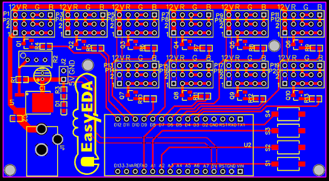
PCB Board Design

Here is the PCB board design for this project.
You can access the actual EasyEDA design by clicking on the image below.

Image source: EasyEDA


PCB Fabrication

After completing the PCB design, you can click on the Fabrication icon.

You will then have access to the PCB order page which will allow you to download your PCB Gerber files that can be sent to any manufacturer. However it is a lot easier (and cheaper) to order it directly from EasyEDA.
Here you can select:

  • the number of PCBs you want to order
  • the number of copper layers you need
  • the PCB thickness
  • copper weight
  • and even the PCB color
After you’ve selected all of the options, click “Save to Cart” and complete you order. You will then get your PCBs shipped a few days later.

Image source: EasyEDA


PCB final product

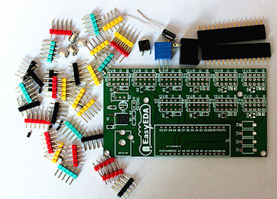
When I received the PCBs, I am quite impressed with the quality, they are pretty nice.

Image source: EasyEDA


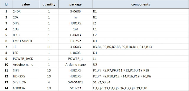
PCB Build of Materials

Image source: EasyEDA


PCB connections

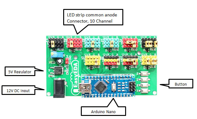
Connect the LED strips through the connection points in the board. Make sure that you connect these correctly (push the connectors all the way onto the pin), because the chances of a short increase significantly with the number of wires connected. Once all the connections are done all that left is to install your Arduino Nano (pre-programmed with the Arduino code above), and to power the PCB with a 12V power supply.


Image source: EasyEDA


Project Video


Concluding comments

Hope you like this RGB light effects project, do try it out and post your feedback below.
 
Disclaimer:
This is a guest blog post by the EasyEDA team. All information within this post was provided by EasyEDA.

ScottC 11 Sep 07:09

EasyEDA RGB5050 LED Scroll Bar


Guest Post Disclaimer

This is a guest post by the EasyEDA team. I would like to thank EasyEDA for providing this tutorial for everyone to enjoy. All information within this post was provided by EasyEDA.


Description

None of us could deny the fact that we would love with to play with LED’s and lighting stuff. I love to play with LED’s and create attractive lighting effects. This project was a result of such an attempt where I created a stunning RGB light effect using the popular development platform Arduino Nano. Let’s see the circuit, code and instruction on building this project:


Image source: EasyEDA


Arduino Libraries and IDE

No libraries are required for this project. The Arduino IDE can be downloaded from the Arduino website. Here is the download link.

ARDUINO CODE:


Preparing the LED strips

Cut down the LED strips into 10 single pieces. Make sure you cut them into equal halves and make sure that only the copper conduction plate in the strip is cut. Making a wrong cut disrupts the electrical conductivity between the LED’s. After cutting down into separate strips, you will need to connect each strip using a Dupont wire connectors.

Image source: EasyEDA


Designing the Control Board

I have made a custom control board that incorporates an Arduino Nano. The control board is used to boost the incoming signal from Arduino and lights up the corresponding LED strips.


Image source: EasyEDA


Control Board Circuit diagram

I used a free Online circuit and PCB designing platform called EasyEDA to develop my control board. It is pretty easy to use especially because of the large library of parts to choose from. Once the design is complete, you have the option to order it through EasyEDA. They offers great prices on custom PCB manufacturing. I have added 10 connection points for 10 LED strips. Each RGB LED strip is controlled by one of the Arduino Nano digital pins.. Transistors Q1,Q2,Q3….Q10 act as a switch for these LED strips for controlling 12V strips via a 5V signal from the Arduino. And switches S1,S2..S4 were added to be able to select the effect on the strip. The schematic can be seen below:


Schematic

You can access the actual EasyEDA schematic by clicking on the image below:

Image source: EasyEDA


PCB Board Design

Here is the PCB board design for this project.
You can access the actual EasyEDA design by clicking on the image below.

Image source: EasyEDA


PCB Fabrication

After completing the PCB design, you can click on the Fabrication icon.

You will then have access to the PCB order page which will allow you to download your PCB Gerber files that can be sent to any manufacturer. However it is a lot easier (and cheaper) to order it directly from EasyEDA.
Here you can select:

  • the number of PCBs you want to order
  • the number of copper layers you need
  • the PCB thickness
  • copper weight
  • and even the PCB color
After you’ve selected all of the options, click “Save to Cart” and complete you order. You will then get your PCBs shipped a few days later.

Image source: EasyEDA


PCB final product

When I received the PCBs, I am quite impressed with the quality, they are pretty nice.

Image source: EasyEDA


PCB Build of Materials

Image source: EasyEDA


PCB connections

Connect the LED strips through the connection points in the board. Make sure that you connect these correctly (push the connectors all the way onto the pin), because the chances of a short increase significantly with the number of wires connected. Once all the connections are done all that left is to install your Arduino Nano (pre-programmed with the Arduino code above), and to power the PCB with a 12V power supply.


Image source: EasyEDA


Project Video


Concluding comments

Hope you like this RGB light effects project, do try it out and post your feedback below.
 
Disclaimer:
This is a guest blog post by the EasyEDA team. All information within this post was provided by EasyEDA.

ScottC 11 Sep 07:09