Anyone can buy a clock, but building your own lets you express your creative flair along the way. [Edison Science Corner] did just that with this neat sci-fi looking design.
The build relies on an Arduino Pro Mini to run the show, paired with a DS3231 real-time clock module. The latter part is of great importance, as without it, the Arduino would not keep accurate time. The 3D printed enclosure looks nondescript from the outside. However, inside, it’s got a neat triangular structure which allows the time to be displayed in that attractive tessellated triangular fashion. There’s a black plastic separator between all the segments which stop unattractive bleed-through and really help with the final effect. The individual triangles are each lit by a NeoPixel LED, which are both addressable and capable of lighting up in RGB colors. It makes for an attractive and colorful display.
This is a rewrite of a project I created in 2010 which brought me a lot of joy, so I hope you enjoy it too.Please read the entire article before starting your own. You can still make it today, the parts are easily available.
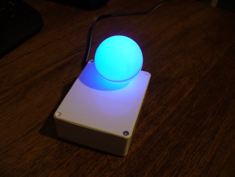
I’ve always enjoyed making Arduino-powered clocks, however over time they tended to become increasingly complex. So to counter this, allow me to introduce you to “Blinky” the one-eyed clock:
It reminds me of the giant killer orb “Rover” from “The Prisoner“… Using a minimal Arduino bootrom system, a DS1307 real time clock IC and an RGB diffused LED, you can make a clock that blinks the time, using the colours of the LED to note different numerical values.
For example, if the time is 12:45, the clock will blink red 12 times, then show blue for a second (think of this as the colon on a digital clock) then blink four times in green (for forty minutes), then blink three times in red for the individual minutes.
If there is a zero, blink blue quickly. Then the clock will not display anything for around forty seconds, then repeat the process. Here he (she, it?) is blinking the time:
Setting the clock is simple. It is set to start at 12:00 upon power up. So for the first use you have to wait until about five seconds before midday or midnight, then power it up. To save cost it doesn’t use a backup lithium battery on the real-time clock IC, but you could add one if required. So let’s get started.
The first thing to do was test the RGB LED for brightness levels, so I just connected it to the digital output pins of my Arduino-compatible board via suitable current-limiting resistors. Red, green and blue to D9, D10 and D11 respectively. Each LED is going to be different, so to ensure maximum brightness without causing any damage you need to calculate the appropriate resistor values.
This is quite easy, the formula is: resistor (ohms) = voltage drop / LED current So if you have a 5V supply, and LED that needs only 2 volts, and draws 20 milliamps (0.2 amps) , the calculation will be: resistor = (5-2)/0.02 = 150 ohms. To be safe I used 180 ohm resistors. The LED was tested with this simple sketch:
/*
  blinky LED test
 */

int red = 2;
int green = 3;
int blue = 4;
int d = 300;
void setup()
{
  pinMode(red, OUTPUT);
  pinMode(green, OUTPUT);
  pinMode(blue, OUTPUT);
}

void loop()
{
  digitalWrite(red, HIGH);
  delay(d);
  digitalWrite(red, LOW);
  delay(d);
  digitalWrite(green, HIGH);
  delay(d);
  digitalWrite(green, LOW);
  delay(d);
  digitalWrite(blue, HIGH);
  delay(d);
  digitalWrite(blue, LOW);
  delay(d);
}
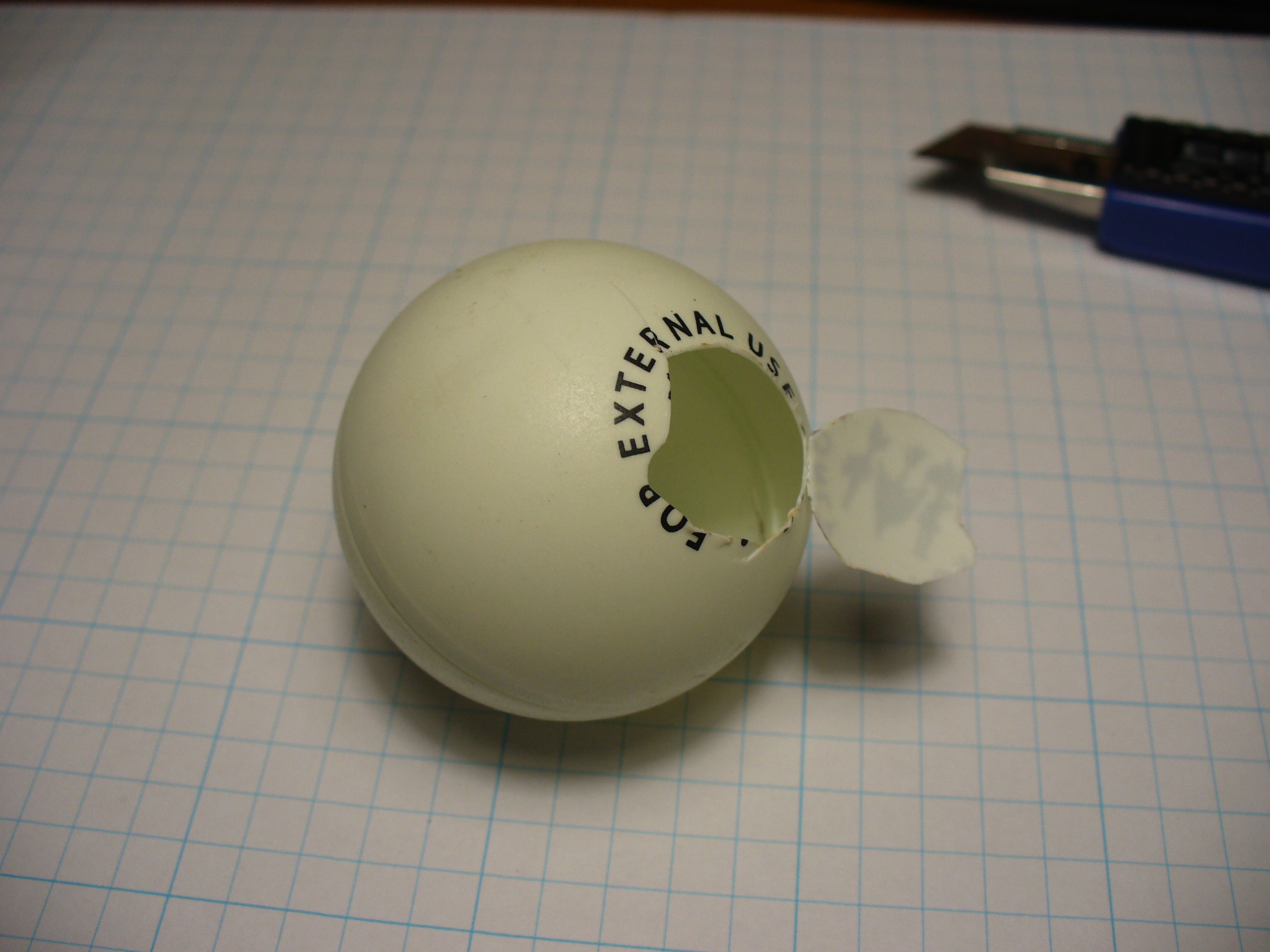
It was interesting to alter the value of d, the delay variable, to get an idea for an appropriate blinking speed. Originally the plan was to have the LED in a photo frame, but it was decided to mount a ping-pong ball over the LED for a retro-style look. Here is a short video of the result of the test:
If you are going to use a ping-pong ball, please be careful when cutting into it with a knife, initially it may require a lot of force, but once the knife cuts through it does so very quickly.
Now it was time to develop the sketch to convert time into blinks. The sketch itself is quite simple. Read the hours and minutes from the DS1307 timer IC; convert the hours to 12 hour time; then blink an LED for the number of hours, display another colour for the colon; divide the minutes by ten and blink that in another colour; then the modulus of minutes and ten to find the individual minutes, and blink those out. Here is the first test sketch:
/*
  "blinky" the one-eyed clock
  Version beta 1
  John Boxall August 2010/6th April 2022 - http://tronixstuff.com
  DS1307/i2c timekeeping based on code by Maurice Ribble 17-4-2008 -     http://www.glacialwanderer.com/hobbyrobotics
*/

#include "Wire.h"
#define DS1307_I2C_ADDRESS 0x68

int red = 9; // LEDs connected to these pins as you might want to PWM them to alter brightness
int green = 10;
int blue = 11;

// Convert normal decimal numbers to binary coded decimal
byte decToBcd(byte val)
{
  return ( (val / 10 * 16) + (val % 10) );
}

// Convert binary coded decimal to normal decimal numbers
byte bcdToDec(byte val)
{
  return ( (val / 16 * 10) + (val % 16) );
}

void setDateDs1307(byte second,        // 0-59
                   byte minute,        // 0-59
                   byte hour,          // 1-23
                   byte dayOfWeek,     // 1-7
                   byte dayOfMonth,    // 1-28/29/30/31
                   byte month,         // 1-12
                   byte year)          // 0-99
{
  Wire.beginTransmission(DS1307_I2C_ADDRESS);
  Wire.write(0);
  Wire.write(decToBcd(second));    // 0 to bit 7 starts the clock
  Wire.write(decToBcd(minute));
  Wire.write(decToBcd(hour));
  Wire.write(decToBcd(dayOfWeek));
  Wire.write(decToBcd(dayOfMonth));
  Wire.write(decToBcd(month));
  Wire.write(decToBcd(year));
  Wire.write(0x10); // sends 0x10 (hex) 00010000 (binary) to control register - turns on square wave
  Wire.endTransmission();
}

void getDateDs1307(byte *second,
                   byte *minute,
                   byte *hour,
                   byte *dayOfWeek,
                   byte *dayOfMonth,
                   byte *month,
                   byte *year)
{
  // Reset the register pointer
  Wire.beginTransmission(DS1307_I2C_ADDRESS);
  Wire.write(0);
  Wire.endTransmission();
  Wire.requestFrom(DS1307_I2C_ADDRESS, 7);
  *second     = bcdToDec(Wire.read() & 0x7f);
  *minute     = bcdToDec(Wire.read());
  *hour       = bcdToDec(Wire.read() & 0x3f);  // Need to change this if 12 hour am/pm
  *dayOfWeek  = bcdToDec(Wire.read());
  *dayOfMonth = bcdToDec(Wire.read());
  *month      = bcdToDec(Wire.read());
  *year       = bcdToDec(Wire.read());
}

void blinkLED(int colour, int ondelay, int offdelay, int blinks)
// blinks LED on pin 'colour' for 'blinks' times with on and off delay of 'ondelay', 'offdelay'
// colour: 9 is red, 10 is green, 11 is blue
{
  for (int a = 0; a < blinks; a++) {
    digitalWrite(colour, HIGH); delay(ondelay); digitalWrite(colour, LOW); delay(offdelay);
  }
}

void blinkTime() // blinks the time
{
  byte second, minute, hour, dayOfWeek, dayOfMonth, month, year;
  float aa;
  int bb;

  getDateDs1307(&second, &minute, &hour, &dayOfWeek, &dayOfMonth, &month, &year);
  // convert hours from 24 to 12 hour time
  if (hour == 0)
  {
    hour = 12;
  }
  if (hour > 12)
  {
    hour = hour - 12;
  }
  blinkLED(9, 500, 500, hour); // blink hours in red
  blinkLED(11, 1000, 500, 1); // show blue for one second
  aa = minute;
  aa = aa / 10;
  bb = int(aa); // find the value of tens of minutes (0~5)
  if (bb > 0)
  {
    blinkLED(10, 500, 500, bb); // blink tens of minutes
  }
  if (bb == 0) // but if the time is something like 03:02?
  {
    blinkLED(11, 200, 200, 1); // blink blue quickly for zero
  }
  aa = minute % 10; // find modulo of minutes to get single minutes
  if (bb > 0)
  {
    blinkLED(9, 500, 500, bb);
  }
  if (bb == 0)
  {
    blinkLED(11, 200, 200, 1); // blink blue quickly for zero
  }
}

void setup()
{
  byte second, minute, hour, dayOfWeek, dayOfMonth, month, year;
  Wire.begin();
  second = 0;
  minute = 17;
  hour = 4;
  dayOfWeek = 6; // these values are moot, but need to store something
  dayOfMonth = 28;
  month = 5;
  year = 10;
  setDateDs1307(second, minute, hour, dayOfWeek, dayOfMonth, month, year);
  pinMode(red, OUTPUT);
  pinMode(green, OUTPUT);
  pinMode(blue, OUTPUT);
}

void loop()
{
  blinkTime();
  delay(5000);
}
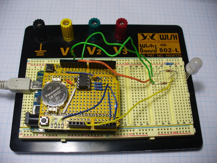
Finally, the code was tested using the Arduino-compatible board and my home-made DS1307 real time clock shield (hey it was 2010, DS32xx were expensive). It is best to use existing hardware while testing, before committing to purchasing new hardware and so on. So here it is on the breadboard:
Here is the prototype in action:
If you’re wondering why the videos are potato-cam quality, smartphones couldn’t record using 4K Ultra HD in 2010.
But perhaps the first version was a little bland. By using analogWrite() we can control the brightness of the LED segments. So I’ve added two more functions, whiteGlow() and blueGlow(); whose purpose is to make the display “glow” by increasing then decreasing the brightness.
And I’ve scaled back the amount of blinking, to make blinky less obvious. So now the display will glow white to announce the forthcoming display of time, wait a second, blink the time (with a blue glowing colon) then stay dark for ten seconds before repeating the process. Here is a quick demonstration of this display style:
Here is the sketch for the above demonstration, and the final one I will use with the hardware prototype:
/*
  "blinky" the one-eyed clock - Version 2.1
  John Boxall 04 August 2010/6th April 2022
  IDGAF licence
  DS1307/i2c timekeeping based on code by Maurice Ribble
  17-4-2008 - http://www.glacialwanderer.com/hobbyrobotics
*/

#include "Wire.h"
#define DS1307_I2C_ADDRESS 0x68

int red = 9; // LEDs connected to these pins as you might want to PWM them to alter brightness
int green = 10;
int blue = 11;

// Convert normal decimal numbers to binary coded decimal
byte decToBcd(byte val)
{
  return ( (val / 10 * 16) + (val % 10) );
}

// Convert binary coded decimal to normal decimal numbers
byte bcdToDec(byte val)
{
  return ( (val / 16 * 10) + (val % 16) );
}

void setDateDs1307(byte second,        // 0-59
                   byte minute,        // 0-59
                   byte hour,          // 1-23
                   byte dayOfWeek,     // 1-7
                   byte dayOfMonth,    // 1-28/29/30/31
                   byte month,         // 1-12
                   byte year)          // 0-99
{
  Wire.beginTransmission(DS1307_I2C_ADDRESS);
  Wire.write(0);
  Wire.write(decToBcd(second));    // 0 to bit 7 starts the clock
  Wire.write(decToBcd(minute));
  Wire.write(decToBcd(hour));
  Wire.write(decToBcd(dayOfWeek));
  Wire.write(decToBcd(dayOfMonth));
  Wire.write(decToBcd(month));
  Wire.write(decToBcd(year));
  Wire.write(0x10); // sends 0x10 (hex) 00010000 (binary) to control register - turns on square wave
  Wire.endTransmission();
}

void getDateDs1307(byte *second,
                   byte *minute,
                   byte *hour,
                   byte *dayOfWeek,
                   byte *dayOfMonth,
                   byte *month,
                   byte *year)
{
  // Reset the register pointer
  Wire.beginTransmission(DS1307_I2C_ADDRESS);
  Wire.write(0);
  Wire.endTransmission();
  Wire.requestFrom(DS1307_I2C_ADDRESS, 7);
  *second     = bcdToDec(Wire.read() & 0x7f);
  *minute     = bcdToDec(Wire.read());
  *hour       = bcdToDec(Wire.read() & 0x3f);  // Need to change this if 12 hour am/pm
  *dayOfWeek  = bcdToDec(Wire.read());
  *dayOfMonth = bcdToDec(Wire.read());
  *month      = bcdToDec(Wire.read());
  *year       = bcdToDec(Wire.read());
}

void blinkLED(int colour, int ondelay, int offdelay, int blinks)
// blinks LED on pin 'colour' for 'blinks' times with on and off delay of 'ondelay', 'offdelay'
// colour: 9 is red, 10 is green, 11 is blue
{

  for (int a = 0; a < blinks; a++)
  {
    digitalWrite(colour, HIGH);
    delay(ondelay);
    digitalWrite(colour, LOW);
    delay(offdelay);
  }
}

void blinkTime()
// blinks the time
{
  byte second, minute, hour, dayOfWeek, dayOfMonth, month, year;
  float aa;
  int bb;
  getDateDs1307(&second, &minute, &hour, &dayOfWeek, &dayOfMonth, &month, &year);

  // convert hours from 24 to 12 hour time
  if (hour == 0)
  {
    hour = 12;
  }
  if (hour > 12)
  {
    hour = hour - 12;
  }
  blinkLED(9, 500, 500, hour); // blink hours in red
  blueGlow(1, 10);
  aa = minute;
  aa = aa / 10;
  bb = int(aa); // find the value of tens of minutes (0~5)
  if (bb > 0)
  {
    blinkLED(10, 500, 500, bb); // blink tens of minutes
  }
  if (bb == 0) // but if the time is something like 03:02?
  {
    blinkLED(11, 200, 200, 1); // blink blue quickly for zero
  }
  aa = minute % 10; // find modulo of minutes to get single minutes
  bb = aa;
  if (bb > 0)
  {
    blinkLED(9, 500, 500, bb); // blink tens of minutes
  }
  if (bb == 0)
  {
    blinkLED(11, 200, 200, 1); // blink blue quickly for zero
  }
}

void whiteGlow(int n, int d)
{
  for (int nn = 0; nn < n; nn++)
  {
    for (int a = 0; a <= 255; a++)
    {
      analogWrite(red, a);
      analogWrite(green, a);
      analogWrite(blue, a);
      delay(d);
    }
    for (int a = 255; a >= 0; --a)
    {
      analogWrite(red, a);
      analogWrite(green, a);
      analogWrite(blue, a);
      delay(d);
    }
  }
}

void blueGlow(int n, int d)
{
  for (int nn = 0; nn < n; nn++)
  {
    for (int a = 0; a <= 255; a++)
    {
      analogWrite(blue, a);
      delay(d);
    }
    for (int a = 255; a >= 0; --a)
    {
      analogWrite(blue, a);
      delay(d);
    }
  }
}

void setup()
{
  byte second, minute, hour, dayOfWeek, dayOfMonth, month, year;
  Wire.begin();
  second = 0;
  minute = 17;
  hour = 4;
  dayOfWeek = 6; // these values are moot, but need to store something
  dayOfMonth = 28;
  month = 5;
  year = 10;
  setDateDs1307(second, minute, hour, dayOfWeek, dayOfMonth, month, year); // every time blinky has new batteries, it will start from midnight/midday
  pinMode(red, OUTPUT);
  pinMode(green, OUTPUT);
  pinMode(blue, OUTPUT);
}

void loop()
{
  whiteGlow(1, 10); // glow white - announces that the time will now be shown
  delay(1000); // give people a second to focus on blinky
  blinkTime();
  delay(50000); // wait 50 seconds
}
Once happy with the sketch, I put a fresh ATmega328P-PU with Arduino bootloader in the board and programmed it with the sketch, to be used in the final version. The next step is to build my own hardware. The last hardware unknown is the amount of current the circuit draws. Once I know this the correct voltage regulator and power supply can be decided upon.
I had a fair idea it would be less than 100 milliamps, so I put a 6V battery onto supply duty via a 78L05 5V regulator (data sheet), and recorded the result:
So it varies, between 20.5 and 46 mA. As it only reaches 46 mA for a short time, we could consider the constant draw to be averaged out at 30 mA. I really want this to be able to run from a battery, but without having an external lead-acid battery lurking around, it will need a plug-pack with an output voltage greater than 7V DC.
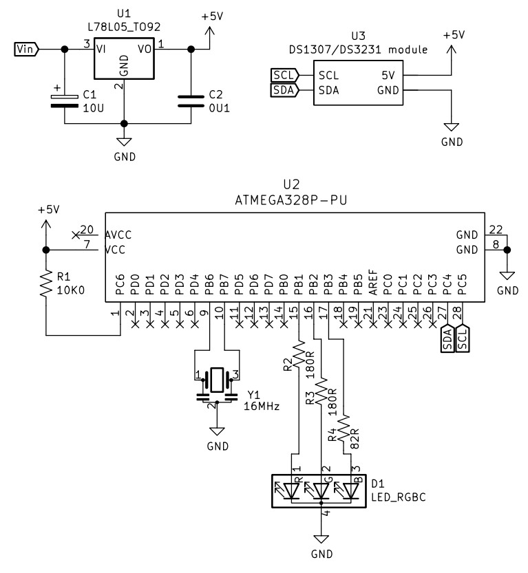
Another alternative would be to run it from a USB socket, a nice source of 5V. If doing so, there wouldn’t be a need for the 78L05 regulator. Which brings us to the circuit diagram, which includes the power regulator. I’ve also altered the resistors to suit the RGB LED used, your values may be different:
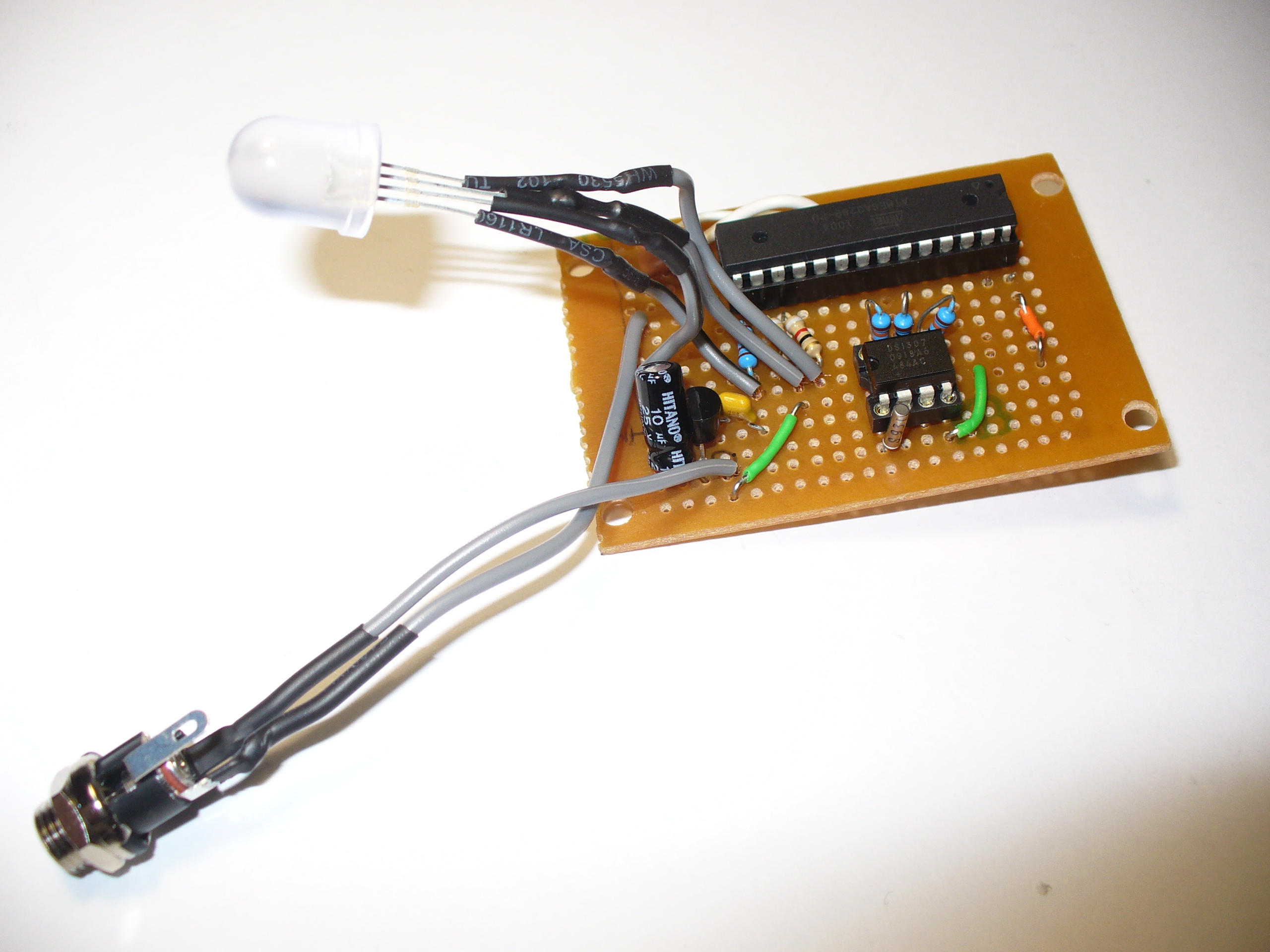
And since it’s 2022, not 2010 – I’ve replaced the DS1307 circuit with a RTC module. Y1 is a three pin 16MHz ceramic resonator, we used those in 2010 as they were cheaper and easier than a crystal and two 22pF capacitors.
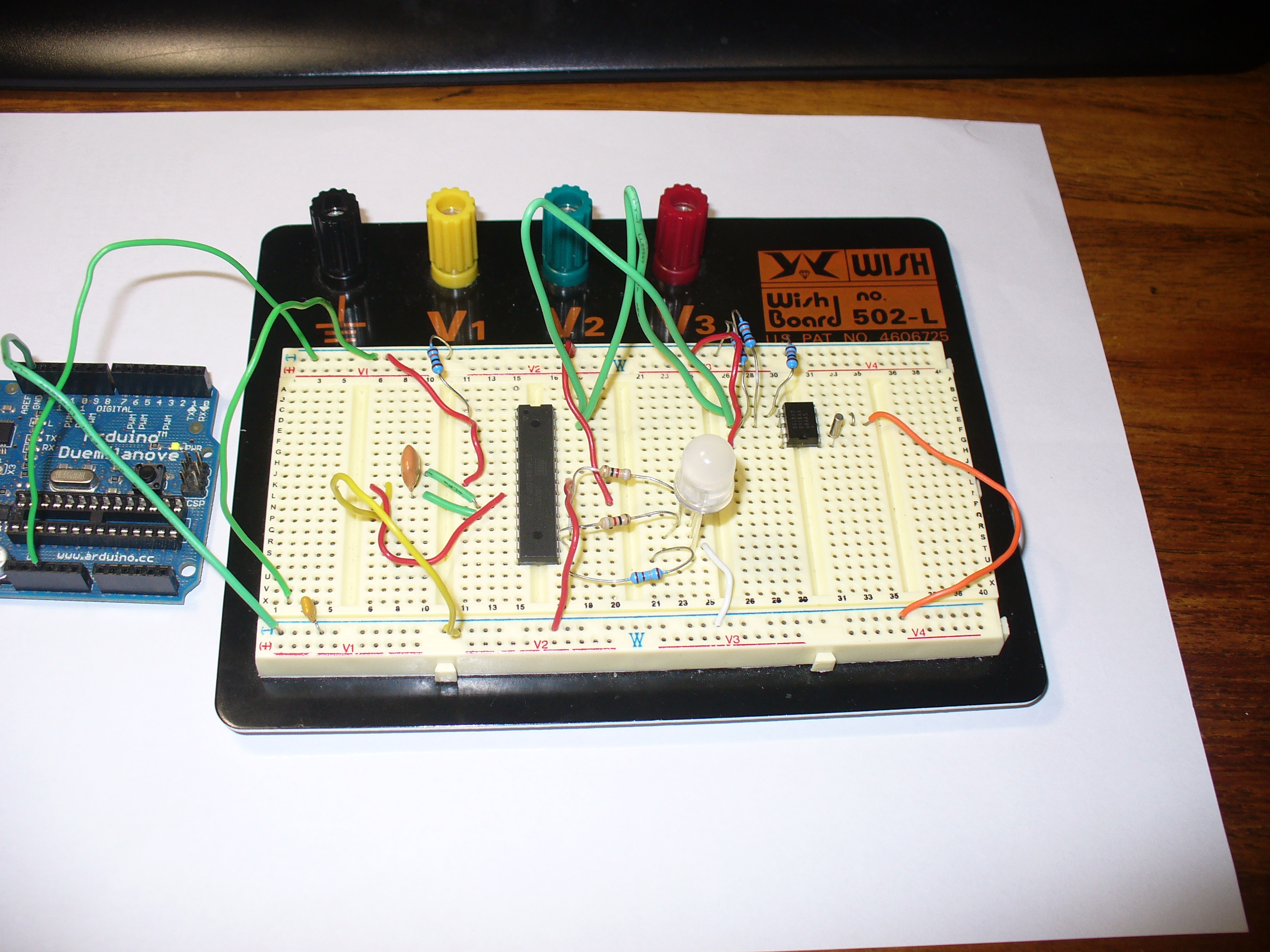
The circuit does not allow for uploading code, so you will need to program the microcontroller on another Arduino or compatible board, then transfer it to the blinky circuit board as described above. At this stage you should test it again – but using a solderless breadboard. In doing so you can make final hardware checks, and generally make sure everything works as it should. This is also a good stage to double-check you are happy with the display behaviour, default time and so on.
Used the Duemilanove as a lazy 5V for testing.
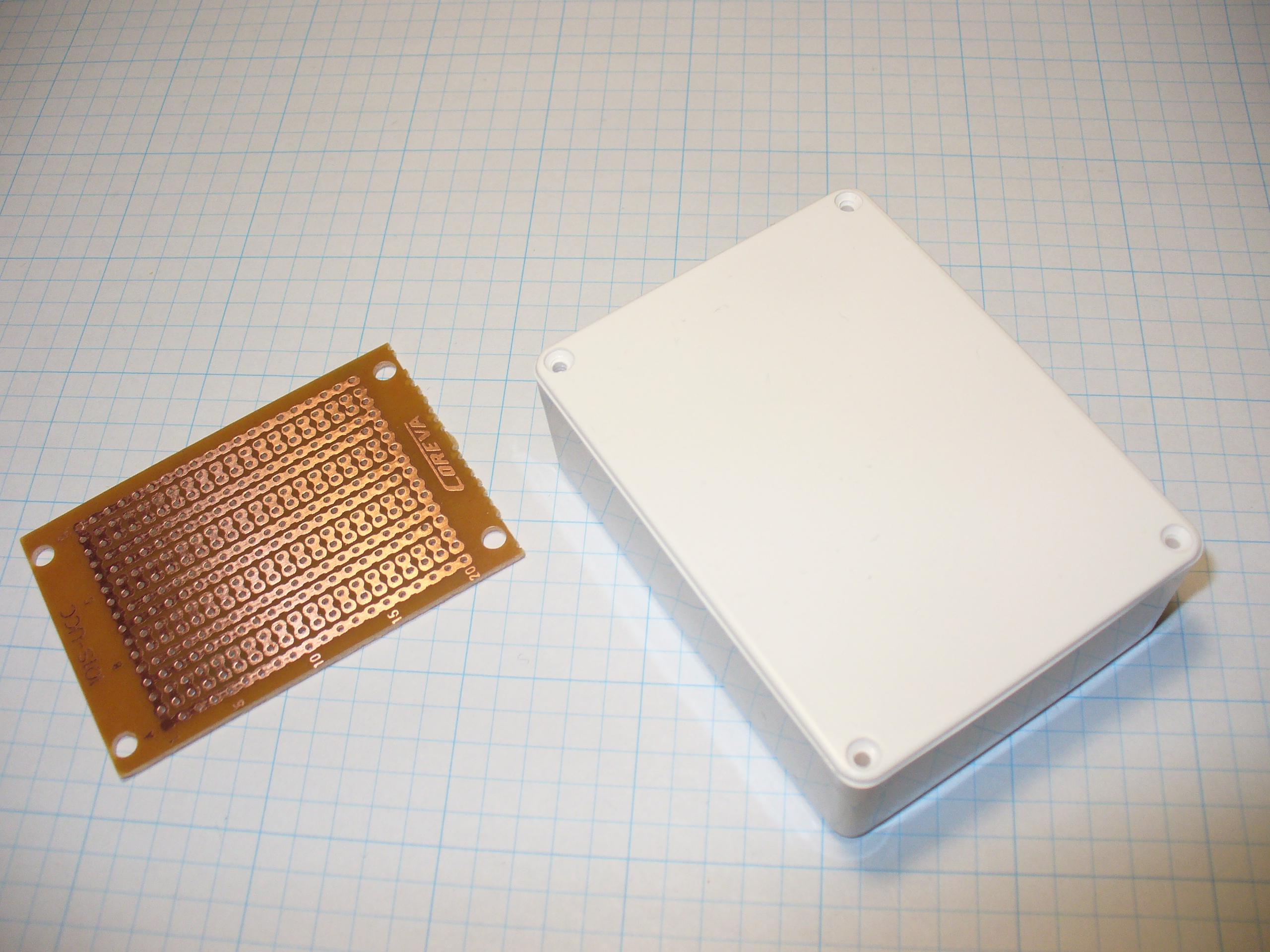
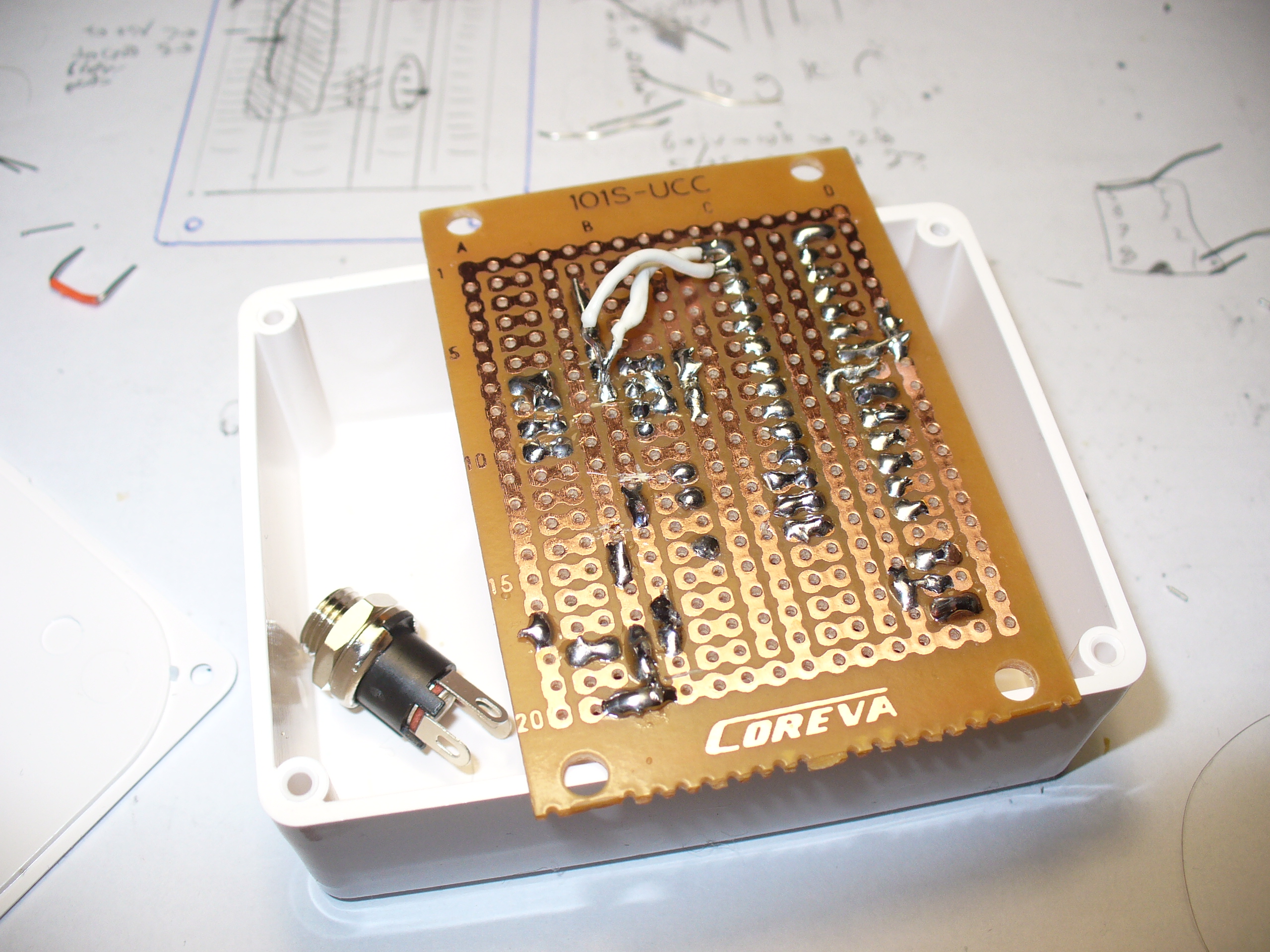
Time to solder up the circuit on some stripboard. Blank stripboard varies, but luckily I found this and a nice box to hold it in:
Stripboard does vary between retailers and so on, so you will need to work out the layout with your own board. In doing so, please double-check your work – follow the layout against the schematic and so on.
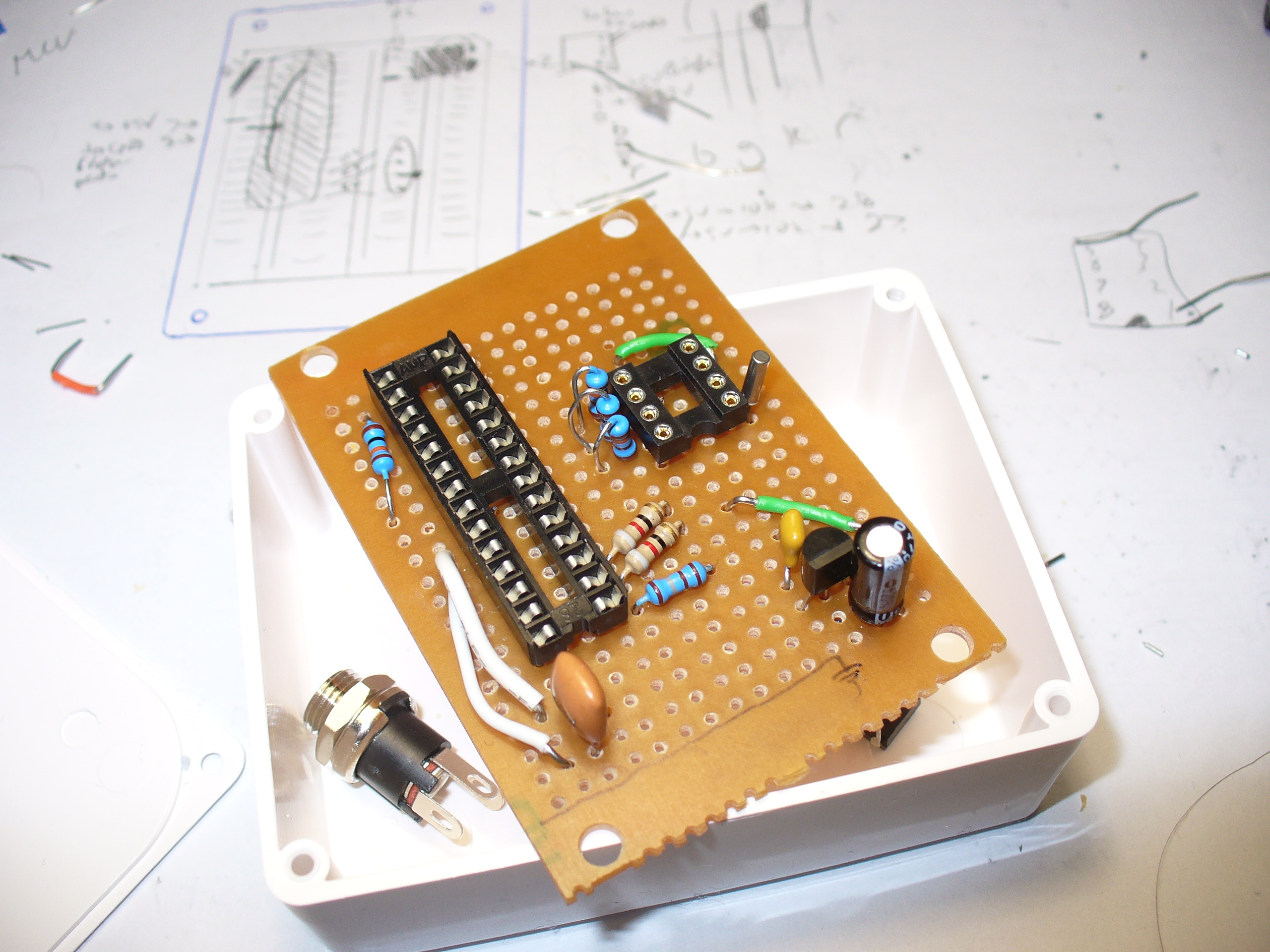
Have a break, then check it again. There is nothing worse than soldering away to realise you are one strip too far over or something. My hand-eye coordination is not the best, therefore my soldering isn’t pretty, but it works:
Note that the images above are using the 2010 circuit – which had a DS1307 sub-circuit.
One would say that there is a good argument for making your own PCBs… and I would agree with that. In 2010 it wasn’t that easy or inexpensive. Now you have KiCAD and Chinese PCB fabs tripping over themselves to give you cheap boards.
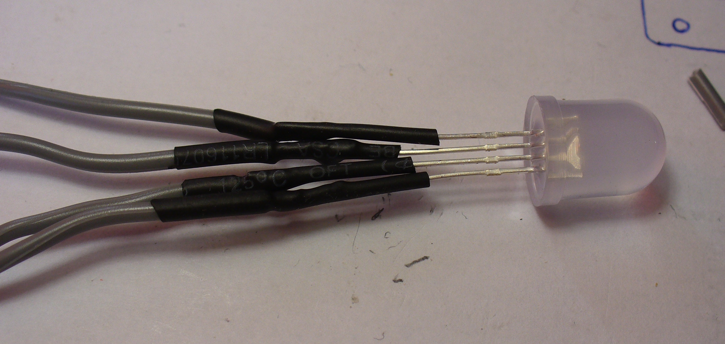
The LED is soldered to some short leads to give it a bit of play, and some heatshrink over the legs to keep them isolated:
And finally, to add a DC socket to feed blinky some power:
The last thing was to check the soldering once more under natural light, to check for bridges or shorts, then have a cup of tea. Upon my return I drilled out a hole in the enclosure lid for the LED, and one one the side for the DC socket, and fitted the lot together… and success! It worked.
I hope you enjoyed making this or at least reading about it. If you find this sort of thing interesting, please consider ordering one or both of my books from No Starch Press, or other book sellers:
Back in the old days, we didn’t have fancy digital clocks. No, we had good analog clocks with a big hand and a little hand, and if you wanted to know the time you had to look at the clock and figure out which number each hand was pointing at, or kind of pointing at. It wasn’t easy, and we liked it that way.
So now, along comes an analog clock that’s nothing but the hands — no dial, no numbers, just hands. How is such a thing possible? The clue is in the clock’s name: AKUROBATTO, and in the video below, which shows the acrobatic movements of the clock’s hands as it does its thing. Serial improbable-clock maker [ekaggrat singh kalsi] clearly put a lot of thought into this mechanism, which consists of the hands and a separate base. The hands are joined together at one end and powered by small stepper motors. The base has two docking areas, where servo-driven claws can grasp the hand assembly, either at the center pivot or at the tip of either hand. With a little bit of shuffling around at transition points, the hands sweep out the hours and minutes in a surprisingly readable way.
For as cool as the design of AKUROBATTO is, the internals are really something else. There are custom-built slip rings to send power to the motors and the Arduinos controlling them, sensors to determine the position of each hand, and custom gearboxes for the steppers. And the locking mechanisms on the base are worth studying too — getting that right couldn’t have been easy.
All in all, an impressive build. Whether displaying the time on a phosphorescent screen or a field of sequins, it seems like [ekaggrat] has a thing for unique clocks.
Electric utilities across the world have been transitioning their meters from the induction analog style with a distinctive spinning disc to digital “smart” meters which aren’t as aesthetically pleasing but do have a lot of benefits for utilities and customers alike. For one, meter readers don’t need to visit each meter every month because they are all networked together and can download usage data remotely. For another, it means a lot of analog meters are now available for projects such as this clock from [Monta].
The analog meters worked by passing any electricity used through a small induction motor which spun at a rate proportional to the amount of energy passing through it. This small motor spun a set of dials via gearing in order to keep track of the energy usage in the home or business. To run the clock, [Monta] connected a stepper motor with a custom transmission to those dials for the clock face because it wasn’t possible to spin the induction motor fast enough to drive the dials. An Arduino controls that stepper motor, but can’t simply drive the system in a linear fashion because it needs to skip a large portion of the “minutes” dials every hour. A similar problem arises for the “hours” dials, but a little bit of extra code solves this problem as well.
Once the actual clock is finished, [Monta] put some finishing touches on it such as backlighting in the glass cover and a second motor to spin the induction motor wheel to make the meter look like it’s running. It’s a well-polished build that makes excellent use of some antique hardware, much like one of his other builds we’ve seen which draws its power from a Stirling engine.
We around the Hackaday shop never get tired of seeing new ways to mark the passage of time. Hackers come up with all manner of interesting timekeeping modalities using every imaginable material and method of moving the mechanism once per whatever minimum time unit the hacker chooses to mark.
But honestly, there are only so many ways to make a clock, and while we’re bound to see some repeats, it’s still nice to go over old ground with a fresh approach. Take this linear sliding stencil clock for instance. [Luuk Esselbrugge] has included some cool design elements that bear a closer look. The video below shows that the display is made up of four separate stepper motors, each driving a vertical stencil via a rack-and-pinion mechanism. There a simple microswitch for homing the display, and a Neopixel for lighting things up.
The video below shows that the stencils move very, very slowly; [Luuk] says that this is to keep the steppers as quiet as possible. Still, this means that some time changes take more than a minute to accomplish, which is a minor problem. The Neopixel also doesn’t quite light up just one digit, which should be a pretty easy fix for version 2. Still, even with these issues, we like the stately movements of this clock, and appreciate [Luuk]’s attempts to make it easier to live with.
Don’t let the number of clocks you see on these pages dissuade you from trying something new, or from putting your twist on an old design. Start with fridge magnets, an old oscilloscope, or even a bevy of steel balls, and let your imagination run wild. Just make sure to tell us all about it when you’re done.
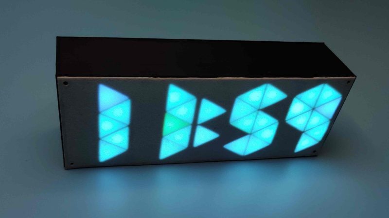
Just when we think we’ve seen all possible combinations of 3D printing, microcontrollers, and pretty blinkenlights coming together to form DIY clocks, [Mukesh_Sankhla] goes and builds this geometric beauty. It’s kaleidoscopic, it’s mosaic, and it sorta resembles stained glass, but is way cheaper and easier.
The crucial part of the print does two jobs — it combines a plate full of holes for a string of addressable RGB LEDs with the light-dividing walls that turn the LEDs into triangular pixels. [Mukesh] designed digits for a clock that each use ten triangles. You’d need an ESP8266 to run the clock code, or if you’d rather sit and admire the rainbow light show unabated by the passing of time, just use an Arduino Uno or something similar.
Most of the aesthetic magic here is in the printed pieces and the FastLED library. It has a bunch of really cool animations baked in that look great with this design. Check out the demo video after the break. The audio is really quiet until the very end of the video, so be warned. In our opinion, the audio isn’t necessary to follow along with the build.
The humble clock takes many lovely forms around here, including pop art.
Along with all the colorful, geometric influence of Memphis design everywhere, giant wristwatch clocks were one of our favorite things about the 80s. We always wanted one, and frankly, we still do. Evidently, so did [Kothe]. But instead of some splashy Swatch-esque style, [Kothe] went the nerdy route by building a giant Casio F-91W to hang on the wall.
Not only does it look fantastic, it has the full functionality of the original from the alarm to the stopwatch to the backlit screen. Well, everything but the water resistance. The case is 3D-printed, as are the buckle and the buttons. [Kothe] might have printed the straps, but they were too big for the bed. Instead, they are made of laser-cut foam and engraved with all the details.
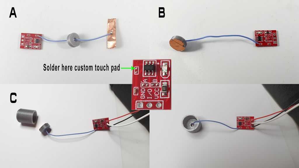
Inside there’s a 7″ touch display, a real-time clock module, and an Arduino Mega to make everything tick. To make each of the printed buttons work, [Kothe] cleverly extended a touch sensor module’s input pad with some copper tape. We think this could only be more awesome if it were modeled after one of Casio’s calculator watches, but that might be asking too much. Take a few seconds to watch the demo after the break.
If we asked you to rattle off all the tools at your own personal disposal, you’d probably leave your timepieces off the list. But we say clocks are definitely tools — cool tools that come in countless forms and give meaning to endless days.
A clock form we hadn’t considered was that of an actual tool. So we were immeasurably delighted to see [scealux]’s clock made from a measuring tape. At least, the time-telling part of the clock is made from a measuring tape. The case isn’t really from a tape measure — it’s entirely printed, Bondo’d, sanded, and painted so well that it’s quite easy to mistake it for the real thing.
Tightly packed inside this piece of functional art is an Arduino Nano and a DS3231 precision RTC module, which we think is fitting for a tool-based clock. The Nano fetches the time and drives a stepper motor that just barely fits inside. There’s just enough tape wound around the printed hub to measure out the time in increments of one hour per inch. Take 1/16″ or so and watch the demo and brief walk-through video after the break.
Good clocks are generally those that keep time well. But we think the mark of a great clock is one that can lure the observer into watching time pass. It doesn’t really matter how technical a timepiece is — watching sand shimmy through an hourglass has its merits, too. But just when we were sure that there was nothing new to be done in the realm of 7-segment clocks, [thediylife] said ‘hold my beer’ and produced this beauty.
A total of 28 servos are used to independently control four displays’ worth of 3D-printed segments. The servos pivot each segment back and forth 90° between two points: upward and flat-faced to display the time when called upon, and then down on its side to rest while its not needed.
Circuit-wise, the clock’s not all that complicated, though it certainly looks like a time-consuming build. The servos are controlled by an Arduino through a pair of 16-channel servo drivers, divided up by HH and MM segments. The Arduino fetches the time from a DS1302 RTC module and splits the result up into four-digit time. Code-wise, each digit gets its own array, which stores the active and inactive positions for each servo. Demo and full explanation of the build and code are waiting after the break.
When [tnjyoung] was asked to build a huge lighted clock for a high school theater’s production of Cinderella with only two weeks before opening night, he probably wished for a fairy godmother of his own to show up and do it for him. But he and his team pulled it off, and it looks amazing. That medallion in the middle? It was laid out painstakingly by hand, using electrical tape.
This thing is 12 feet wide and weighs more than 500 pounds. Even so, it isn’t a permanent set piece, so it has to move up and down throughout the show on airplane cables. Now for the minutiae: there’s an Arduino Uno with built-in Wi-Fi that receives UDP commands from a phone to raise and lower the clock at the appropriate times. The ‘duino is also controlling two stepper motors, one for the hour hand and one for the minute hand.
Time is almost a minor character in the story of Cinderella, since she has to get back by midnight. Because of this, [tnjyoung] programmed a dozen or so time cues that move the steppers at various speeds to achieve different effects, like time flying by as she dances the night away with the Prince. Hour you still just sitting there? Sweep past the break to watch the build process fly by in a matter of minutes.