Posts with «7-segment display» label

World’s Cutest Pomodoro Timer Is Also a Clock

Student and hacker [prusteen] recently fell in love with the Pomodoro method of time management. That’s where you concentrate on your task for 25 minutes, then take a five-minute break, and repeat this four times with a longer break at the end. Initially, [prusteen] was keeping track on their phone, but hated having to change the timer value between Pomodoros and break times. In order to keep the flow mode engaged, [prusteen] came up with this darling little study buddy that does it all with the push of a button.

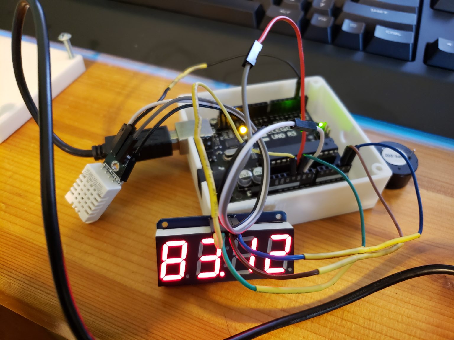
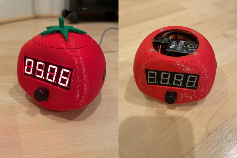
By default, this tomato shows the current time, which we think is a handy and often-overlooked feature of Pomodoro timer builds. Press that momentary switch on the front, and it starts counting upward to 25 minutes. Then it beeps in stereo through a pair of buzzers when the time is up, and automatically starts a five-minute break timer. Press it again and the display goes back to clock mode, although judging by the code, doing this will cancel the timer.

Inside the juicy enclosure is an Arduino Nano, an RTC, and a 7-segment display. We love the attention to detail here, from the little green leaves on top to the anatomically-correct dimple on the underside. And we always like to see lids that snap on with magnets. So satisfying. Check out the brief demo after the break, which unfortunately does not include any lid-snapping action.

Do you need more interaction with your Pomodoro timer? Build yourself a pomo-dachi instead.

Handheld Farkle Really Sparkles

Farkle is a classic dice game that only requires 6 dice and a way to write down scores based on the numbers rolled. Even so, this type of game isn’t inherently portable — it would be fairly difficult to play on a road trip, for instance. [Sunyecz22] decided that Farkle would make an excellent electronic game and got to work designing his first PCB.

This little game has everything you could want from a splash screen introduction to a handy scoring guide on the silkscreen. After choosing the number of players, the first player rolls using the momentary button and the electronic dice light up to indicate what was rolled. As long as the player rolled at least one scoring die, they can take the points by selecting the appropriate die/dice with the capsense pads, and either pass or keep going. The current player’s score is shown on the 7-segment, and the totals for each player are on the OLED screen at the bottom.

The brains of the operation is an Arduino Pro Mini. It controls two MAX7219s that drive the 42 LEDs plus the 7-segment display. A game like this is all in the code, and lucky for us, [Sunyecz22] made it available. We love how gorgeous the glossy 3D printed enclosure looks — between the glossy finish and the curved back, it looks very comfortable to hold. In the future, [Sunyecz22] plans to make a one player versus the computer mode. Check out the demo and walk-through video after the break.

The capsense modules are a great touch, but some people want a little more tactility in their handheld games. We say bring on the toggle switches.

This Freezer Failure Alarm Keeps Your Spoils Unspoiled

Deep freezers are a great thing to have, especially when the world gets apocalyptic. Of course, freezers are only good when they’re operating properly. And since they’re usually chillin’ out of sight and full of precious goods, keeping an eye on them is important.

When [Adam] started looking at commercial freezer alarms, he found that most of them are a joke. A bunch are battery-powered, and many people complain that they’re too quiet to do any good. And you’d best hope that the freezer fails while you’re home and awake, because they just stop sounding the alarm after a certain amount of time, probably to save battery.

If you want something done right, you have to do it yourself. [Adam]’s homemade freezer failure alarm is a cheap and open solution that ticks all the boxen. It runs on mains power and uses a 100dB piezo buzzer for ear-splitting effectiveness to alert [Adam] whenever the freezer is at 32°F/0°C or above.

If the Arduino loses sight of the DHT22 temperature sensor inside the freezer, then the alarm sounds continuously. And if [Adam] is ever curious about the temperature in the freezer, it’s right there on the 7-segment. Pretty elegant if you ask us. We’ve got the demo video thawing after the break, but you might wanna turn your sound down a lot.

You could assume that the freezer is freezing as long as it has power. In that case, just use a 555.

Servo-Powered 7-Segments Choreograph This Chronograph

Good clocks are generally those that keep time well. But we think the mark of a great clock is one that can lure the observer into watching time pass. It doesn’t really matter how technical a timepiece is — watching sand shimmy through an hourglass has its merits, too. But just when we were sure that there was nothing new to be done in the realm of 7-segment clocks, [thediylife] said ‘hold my beer’ and produced this beauty.

A total of 28 servos are used to independently control four displays’ worth of 3D-printed segments. The servos pivot each segment back and forth 90° between two points: upward and flat-faced to display the time when called upon, and then down on its side to rest while its not needed.

Circuit-wise, the clock’s not all that complicated, though it certainly looks like a time-consuming build. The servos are controlled by an Arduino through a pair of 16-channel servo drivers, divided up by HH and MM segments. The Arduino fetches the time from a DS1302 RTC module and splits the result up into four-digit time. Code-wise, each digit gets its own array, which stores the active and inactive positions for each servo. Demo and full explanation of the build and code are waiting after the break.

When it comes to 7-segment displays, we say the more the merrier. Here’s a clock that uses pretty much all of them.

Mechanical 7-segment display made with micro servos and an Arduino Mega

Flip displays are an interesting piece of technology, physically moving segments into place that stay put until other information is needed. Michael Klements has been especially fascinated by these devices, and after inspiration from another project, he decided to craft his own.

His version utilizes 14 micro servos to flip segments into a visible position, then rotate them to 90° when no longer needed. This “off” mode displays a slimmer profile, and the sides and back are painted black, making them much less visible.

An Arduino Mega, with 15 possible PWM outputs, is used to control the servos, while a hobby RC-style battery eliminator circuit provides power to the motors. 

Be sure to check out the build process and in-action shots below! 

Intuitive Arduino clock has seven alarms and three LED displays

Alarm clocks of old—and certainly many of those today—require several button pushes to set things up properly. Maker Michael Wessel, however, decided to implement his own take on a more intuitive clock, creating a device that features three separate eight-digit seven-segment LED panels. Eight buttons allow for direct manipulation of each of the digits, with their own dedicated LEDs.

The info on display includes time and date, as well as temperature, and it can even show how many days, hours, or minutes have passed since a special pre-programmed day. Up to seven audible alarms are available, which can be silenced by a loud noise (e.g. clapping your hands) via a sound sensor. 

The clock is controlled via an Arduino Mega, along with an RTC module to keep things accurate.

I remember I always had to set all digital clocks for my grandparents in the ’80s — these clocks and watches always required some complicated button juggling! So, here it is: a DIY LED alarm clock that my grandparents would have been able to set and use without my help! 

An Arduino-based LED clock with 7 individual alarms, highly intuitive user interface, temperature display, and display of days / hours / minutes passed since a special date, e.g., your birthday. An active / ringing alarm can be disabled by making a loud noise, e.g., by clapping your hands. Timer-based PWM sound output for alarm melodies. 

The Arduino’s EEPROM is being used to store the alarms of course, and the DS3231 RTC is battery backed up, so it survives a temporary power outage and you won’t be late for work the next morning. 

This was put together rather quickly, thanks to off the shelf components, Velcro and existing Arduino libraries for them! The clock can be built for about $30 – 40. 

Check the time on this large and inexpensive “Titan Clock”

When you, perhaps after being late for an important event one too many times, decide to build a wall clock, there are many DIY options from which to choose. But none may be as massive or unique as the aptly named “Titan Clock.”

To justify this particular design, hacker “ProtheanSoft” lists several of its advantages, such as its large size, energy efficiency (runs on a smartphone charger), thinness (only 18mm thick with casing), and of course, affordability.

The Titan Clock—which can be assembled for less than $50—consists of RGB LEDs, inexpensive craft materials like foamcore board, acrylic and aluminum sheets, as well as recycled components including the diffuser from a broken LCD monitor or TV to generate a uniform glow for each segment. 

ProtheanSoft’s project uses an Arduino Nano for control, along with with a DS3231 RTC module for accurate timekeeping. In this version, the Arduino is programmed to display the time and change color every hour based on a predetermined table.

Interested in creating your own? You can find more details on the build here, as well its code and a wiring diagram on GitHub.

DIY Hot Wheels Drag Race Timer

[Apachexmd] wanted to do something fun for his three-year-old son’s birthday party. Knowing how cool race cars are, he opted to build his own Hot Wheels drag race timer. He didn’t take the easy way out either. He put both his electronics and 3D printing skills to the test with this project.

The system has two main components. First, there’s the starting gate. The cars all have to leave the gate at the same time for a fair race, so [Apachexmd] needed a way to make this electronically controlled. His solution was to use a servo connected to a hinge. The hinge has four machine screws, one for each car. When the servo is rotated in one direction, the hinge pushes the screws out through holes in the track. This keeps the cars from moving on the downward slope. When the start button is pressed, the screws are pulled back and the cars are free to let gravity take over.

The second component is the finish line. Underneath the track are four laser diodes. These shine upwards through holes drilled into the track. Four phototransistors are mounted up above. These act as sensors to detect when the laser beam is broken by a car. It works similarly to a laser trip wire alarm system. The sensors are aimed downwards and covered in black tape to block out extra light noise.

Also above the track are eight 7-segment displays; two for each car. The system is able to keep track of the order in which the cars cross the finish line. When the race ends, it displays which place each car came in above the corresponding track. The system also keeps track of the winning car’s time in seconds and displays this on the display as well.

The system runs on an Arduino and is built almost exclusively out of custom designed 3D printed components. Since all of the components are designed to fit perfectly, the end result is a very slick race timer. Maybe next [Apachexmd] can add in a radar gun to clock top speed. Check out the video below to see it in action.


Filed under: Arduino Hacks, toy hacks