Posts with «magnetometer» label

Sensor board for underwater ROV

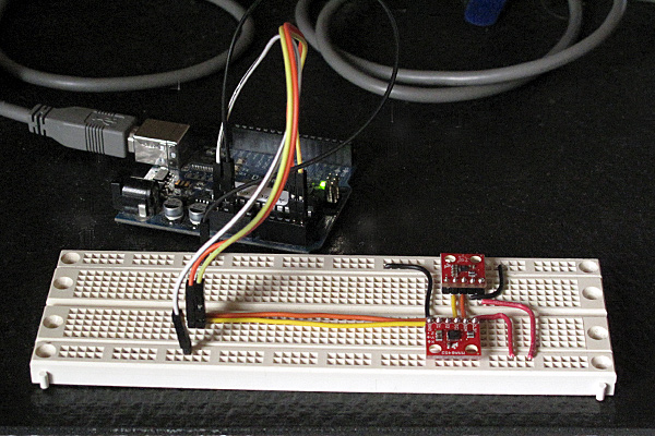
Since I had bought the robotics club an I2C accelerometer and magnetometer, I decided to make a new PC board for them to mount the accelerometer, the magnetometer, and the pressure gauge on the same board.  I don’t have the SMD soldering skills to solder all the chips onto one board, and I already had breakout boards for the accelerometer and magnetometer from Sparkfun, so I decided just to put connectors for those breakout boards onto the back of the pressure sensor board.  (The back, because the pressure sensor on the front has to be stuck through a hole in the dry box and glued in place.

The new boards are tiny (1.05″ × 1.425″), so I decided to try BatchPCB (which has pricing by the square inch) rather than 4pcb.com (which has fixed pricing per board, up to a fairly large size).  The price from BatchPCB was $10 per order plus $2.50/square inch plus $0.90 for shipping, so ordering 3 copies of the board (though I only needed one), cost me $22.12, substantially less than a single board from 4pcb.com, which is $33 plus $17.30 shipping and handling per board (plus an extra $50 if your board has multiple boards on it).  The 4pcb price is lower if your board is bigger than about 15.76 square inches, so even my HexMotor boards (at 12.44 square inches) would be cheaper from BatchPCB.  If you get multiple boards from 4pcb.com on a single panel and cut them apart yourself, the breakeven point is about 35.76 square inches for a single design (so three HexMotor boards from a single 4pcb.com panel is cheaper than from BatchPCB). For multiple designs on a single panel, the 4pcb.com deal is better: for 3 different designs, a total of 27.04 square inches would make 4pcb.com the cheaper way to go.

If you want a copy of the board, you can order it from BatchPCB, or pick up the Eagle files from my web site and order copies from elsewhere.  I’ve put the HexMotor Eagle files on line also, but not put them on the BatchPCB site.  I should probably upload them there sometime.

Bottom line: BatchPCB is better for small numbers of tiny boards, but 4pcb.com is better for larger boards and multiple designs.

The BatchPCB orders came back quite quickly (12 days from order to delivery by mail), though I had been worried because their design-rule check, which they say takes minutes had taken about 8 hours.  The problem was that each check takes a few minutes, but they had hundreds in the queue over the weekend, and it took a full day to clear the queue.

I had less trouble soldering the pressure gauge this time (this was my second attempt at soldering surface mount devices).  You can see in the pictures above that the results are much cleaner than in my first attempt.

The robotics club has tested the pressure sensor on the new board (using their own code on the Arduino) and it seems to work ok,  have drilled the hole in the dry box for the port, and glued the sensor board in place using superglue.  It seems to be waterproof (at least down to 1 foot—we’ve not tested in deep water yet).

Related articles

Tagged: accelerometer, Arduino, BatchPCB, magnetometer, pressure sensor, Printed circuit board, ROV, SparkFun Electronics

Magnetometer and accelerometer read simultaneously

In Learning to Use I2C and Magnetometer not fried, I talked about interfacing the MAG3110 magnetometer and MQA8452Q accelerometer to an Arduino.  For both, I’m using breakout boards from Sparkfun Electronics.

I  checked today that there are no problems when I connect both devices to the same I2C bus.

The first test was very simple: I put both the breakout boards into a breadboard and wired them together, then tried running each of the programs I’d written for the chips separately. Result: no problems—worked first time.

I then tried merging the programs (cleaning up any naming conflicts) so that both could be run from the same code.  After a few typo fixes, this also worked fine

I think I’m now ready to hand over the software to the students to use for their robot.

I still need to put the i2c.h, i2c.cpp, and accel_magnet code in some public place for others to use (perhaps on github? maybe on my web pages at work?) [UPDATE 2012-jan-31: I have put the libraries and the sample code for the accelerometer and magnetometer at http://users.soe.ucsc.edu/~karplus/Arduino/]

One thing that is still missing is doing tilt correction for the compass heading.  Since the ROV is not expected to remain level (the accelerometer is intended to be used in a feedback loop to adjust the pitch, with anything from -90° to +90° being reasonable), getting a good compass heading requires rotating the magnetometer readings into the horizontal plane.  Only one of the students in the robotics club has had trigonometry or matrix math, so I’ll have to work with him to get him to figure out how to do the tilt correction. It may be simplest conceptually  to compute pitch and roll angles first, then rotate twice, rather than trying to do the whole tilt correction in one step (especially since the Arduino does not have matrix libraries).

Related articles

Tagged: accelerometer, Arduino, I²C, magnetometer, robotics, SparkFun, SparkFun Electronics

Magnetometer was not fried

MAG3110 breakout board by Sparkfun

In Learning to Use I2C, I talked about the difficulty I’d been having getting the MAG3110 breakout board from Sparkfun to work, and my fears that I had burned it out by running it overnight at 5v (instead of the rated 3v).  I suspected that my problem was really a software problem, but debugging the software when I was afraid that the hardware was fried seemed like an exercise in futility.

I bought another of the breakout boards from Sparkfun (they’re only $15), and soldered on a header yesterday.  The code failed in almost exactly the same way with the new (presumed good) part as with the old (presumed fried) part, so I was convinced that the problem was indeed in the software.

I spent half of yesterday and most of this morning carefully rewriting the library of I2C interface code.  I was starting with example code from Sparkfun for the MMA8452Q accelerometer, which I had generalized to handle other I2C devices.

The library worked fine with the accelerometer, so I thought it was ok, but it did not work with the magnetometer. I added a lot of error checking (making sure that the microprocessor was in the expected state after each I2C operation), and found that things were not working as expected. The extra error checking made it much easier to diagnose the problems. I had to re-read the I2C documentation in the ATMega328 datasheet several times, to make sure that I had all the details right (I didn’t, of course). The documentation in that data sheet is better than several of the tutorials I’ve seen on line, and is both thorough and comprehensible in describing the interface.

I did not implement all features of the I2C  interface—in fact, I have a rather minimal implementation that uses polling rather than interrupts and assumes that the Arduino will always be the bus master.  Those assumptions are fine for most Arduino projects, which just use the I2C bus for talking to a handful of peripherals, but sometime in the future I may need to make a more complete set of code that can handle multiple masters, the Arduino as a slave device, and interrupts rather than polling and waiting for operations to finish.

Because I was more interested in simplicity and robustness than speed, I rewrote the code so that transactions were finished (and appropriate status checked) before functions returned.  With these changes I found that the STOP condition was not happening, despite being requested.  All other operations on the bus are checked with the TWINT bit  of the TWCR register and the upper bits of the TWSR register, but determining that STOP has completed requires checking the TSWTO bit of the TWCR register. The code I had started from just checked the TWINT bit for the other operations, and had a fixed timeout that was too short—it did no checking at all on the STOP state, just adding a fixed delay.

Once I got the STOP timing cleaned up (and earlier, making sure to send NAK when reading the last byte), everything worked fine.  The accelerometer code  had probably worked ok because there were enough delays after stops that the stops completed, even though I had not checked to make sure.  With the fixed code, even the magnetometer that I thought I had fried seems to work ok.

The interface for the students in the Robotics Club is fairly simple (much simpler than the standard “Wire” library):

// Read one register
uint8_t i2cReadRegister(uint8_t i2c_7bit_address, uint8_t address);
// Read num_to_read registers starting at address
void i2cReadRegisters(uint8_t i2c_7bit_address, uint8_t address, uint8_t num_to_read, uint8_t * dest);

// Write one register
void i2cWriteRegister(uint8_t i2c_7bit_address, uint8_t address, uint8_t data);
// Write num_to_write registers, starting at address
void i2cWriteRegisters(uint8_t i2c_7bit_address, uint8_t address, uint8_t num_to_write, const uint8_t *data);

I suppose I should check that there are no problems when I connect both devices to the same I2C bus, before handing this over to the students to use for their robot.

I should also put the i2c.h and i2c.cpp in some public place for others to use (perhaps on github? maybe on my web pages at work?). It is really a shame that WordPress.com does not permit code-like files as pages.

Related articles

Tagged: accelerometer, Arduino, i2c, magnetometer, robotics, SparkFun, SparkFun Electronics

Learning to use I2C

For the Santa Cruz Robotics Club, I’ve bought three sensors for their underwater ROV: a magnetometer, an accelerometer, and a pressure sensor.

Originally, we were going to an ADXL335 accelerometer (with a breakout board by Adafruit Industries) and an MPXHZ6250A pressure sensor (no magnetometer), for which I designed a small PC board, but once the specs for this year’s mission came out, we saw that they wanted us to determine compass headings for a “sunken ship”, so it seemed a natural thing to add a magnetometer to the hardware.  After looking at what was available, I chose the MAG3110 breakout board from Sparkfun, because it provided a triple-axis magnetometer for only $15.

The MAG3110 is an I2C interface, which means we need only 2 wires to hook it up (and the wires can be shared with other I2C devices).  If we are going to all the trouble of figuring out an I2C interface, I figured we might as well use it for the accelerometer as well, so I got a MMA8452Q breakout board from Sparkfun also.

I decided to do a simple test program for the I2C parts before handing them over to the robotics club, so that they could be sure they had working parts.  It was a good thing I did, because I spent more than an entire day trying to get the parts to work.  I finally gave up on the “Wire” library from the Arduino website, and tried using the i2c.h file from Sparkfun (example code linked to from the accelerometer web page).  I got that working and rewrote the library as a proper .h and .cpp file, so that it could be installed as a normal Arduino library, adding some of the utility calls that had been buried in the MMA8452 demo code.

The MMA8452Q code was working fine, so I tried using the same i2c library for the MAG3110 magnetometer.

I had gotten MAG3110 working with the Wire library, but running at 5v (I’d not noticed that it was a 3.3v part—rather, I thought I’d checked that it was a 5v part, but I was wrong).  I’d left it powered at 5v all night, and I think I burned it out, as it was quite warm in the morning.  Today, I can read and write the registers of the MAG3110, but the xyz values are not coming out reasonable at all—I frequently get the same values (like 0xF9F9)and 0x1DF9), independent of the orientation. If I read all the registers, a lot of them come out as 0xF9 or 0x1D.  Even the WHO_AM_I register (which should be 0xC4) often comes out 0x1D.  I seem to get intermittent correct values for registers, but mostly bogus values.

I’ll feel stupid if I order another part and it turns out to be a software bug, but I’m pretty sure the chip is fried.  But I guess it is time to do another Sparkfun order. (I owe them some business, after calling them for the replacement photointerrupter.)

Incidentally, I tried finding a usable pressure sensor with an I2C interface, but it doesn’t look like anyone is making them except for barometric pressure ranges for dry gases.  I suppose Freescale will eventually come out with a full range of I2C pressure sensors, but my guess is that will be a long time coming, as the automotive and industrial applications have a pretty long product design cycle (unlike consumer electronics, which is driving the barometric pressure sensors).


Tagged: accelerometer, Adafruit Industries, Arduino, magnetometer, robotics, SparkFun, SparkFun Electronics

Underwater ROV again this year

Last year I blogged about MATE ‘s Monterey Bay Regional underwater ROV competition in Underwater ROV contest.  I coached a robotics club at my son’s high school, and they built a small vehicle which they barely got into the water the day before the contest, because we started so late.

Although my son is being home-schooled this year, we have kept the team going, losing one member and picking up another (so we still have only 3).  The robotics club is no longer affiliated with a school, but that makes no difference, as all the school provided us was an inconvenient time to meet (lunch on Tuesdays) and 15 minutes in the pool once.  We meet for 3 hours on Sundays at my house, which gives them enough time to get something done.

I’m still paying the expenses out of my own pocket, and we now have the construction of the vehicle taking up about a third of our living room (the benchtop drill press is the first thing you see on entering the house, unless it is on the floor to make room on the robotics table for the scroll saw).

The students have made considerable progress since last year, having replaced the high-resistance tether and switch box with a low-resistance power wire and a dry box that will house an Arduino microprocessor with H-bridge chips.  They’ve made the tether with a waterproof disconnect and have tested everything for water tightness (though only at bathtub depth, not 10 feet deep).  I think that they’ll have the basic vehicle and electronics finished by the end of January, leaving some time for designing and building mission-specific tools, programming the Arduino and the laptop GUI, and learning to pilot the vehicle.  Now we just have to find a pool to practice in.

The club members have gotten much more independent this year, so my coaching involves my making some suggestions about what they should work on at the beginning of the meeting, checking to see how they are doing about once an hour, and having a discussion with them about what they’ll need to design or build next over snacks near the end of the meeting.  I also try to get them to give me specific parts to buy, but I usually end up having to find and select parts for them.  If the group were bigger (and my wallet more able to tolerate mistakes), I could have the students doing more of the purchasing.

The challenges for this year have been published, and they are in the usual verbose style.  I may have a hard time getting all the students to read the specs carefully, since the specs go on and on with irrelevant “color” hiding the nuggets of critical information.  I’m not looking forward to making the items needed for practicing the missions this year, since they are described in the same wordy way as last year (which I found difficult to follow in several places), and they haven’t even released photos or drawings of what the objects are supposed to look like.  Trying to re-create the objects from the turgid assembly directions without pictures is going to be a nightmare.

The contest does not have any tasks this year that need a depth gauge (but I bought a pressure sensor, so the students will measure depth!), but they will need to determine compass headings, so we’re trying to decide whether to get a cheap compass and put it in the camera view, or add an electronic compass module to the electronics in the dry box.  An electronic compass is definitely cooler, but we may be running out of pins on the Arduino.

Related Articles

Tagged: Arduino, contests, electronic compass, H-bridge, remotely operated underwater vehicle, robotics, ROV