Posts with «zoetrope» label

Flipbook Automation Saves Your Thumb

You’ve probably seen a flipbook. That’s a book with pictures on each page. Each picture is slightly different than the last one so if you flip rapidly through the book you get a little animation. We like the German word, Daumenkino, which translates as “thumb cinema” and that seems appropriate. [Barqunics] put a decidedly new twist on this old technology. His flipbook senses a viewer and automatically flips the pages using a motor. You can see the Arduino-controlled device in the video below.

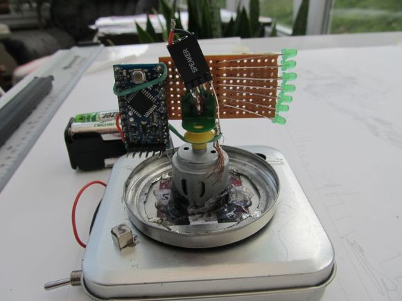
The presence detection is a ubiquitous sonar sensor. The frame is easy to make since it uses cardboard and hot glue. A DC motor like you find on many toy cars or robots provides the rotation. No 3D printing needed, but we did think it would be easy to 3D-print or laser-cut the pieces.

You’d think the flipbook would date back to antiquity, but apparently, the earliest known ones are from the mid-1800s. However, the idea isn’t that different from a phénakisticope or a zoetrope other than those devices use a disk or drum that would be easy to rotate. Something to consider if you plan to recreate this project.

We should have guessed there would be automated ways to generate images for a flipbook. That opens up a lot of interesting ideas for projects, too.

Hack a Day 04 Dec 16:00

POV Display Does it on the Cheap

[Sholto] hacked together this ultra low-budget spinning display. He calls it a zoetrope, but we think it’s actually an LED based Persistence Of Vision (POV) affair. We’ve seen plenty of POV devices in the past, but this one proves that a hack doesn’t have to be expensive or pretty to work!

The major parts of the POV display were things that [Sholto] had lying around. A couple of candy tins, a simple brushed hobby motor, an Arduino Pro Mini, 7 green LEDs, and an old hall effect sensor were all that were required. Fancy displays might use commercial slip rings to transfer power, but [Sholto] made it work on the cheap!

The two tins provide a base for the display and the negative supply for the Arduino. The tins are soldered together and insulated from the motor, which is hot glued into the lower tin. A paper clip contacts the inside of the lid, making the entire assembly a slip ring for the negative side of the Arduino’s power supply. Some copper braid rubbing on the motor’s metal case forms the positive side.

[Sholto] chose his resistors to slightly overdrive his green LEDs. This makes the display appear brighter in POV use. During normal operation, the LEDs won’t be driven long enough to cause damage. If the software locks up with LEDs on though, all bets are off!

[Sholto] includes software for a pretty darn cool looking “saw wave” demo, and a simple numeric display. With a bit more work this could make a pretty cool POV clock, at least for as long as the motor brushes hold up!

[via Instructables]


Filed under: led hacks