Single digit clock - method and apparatus
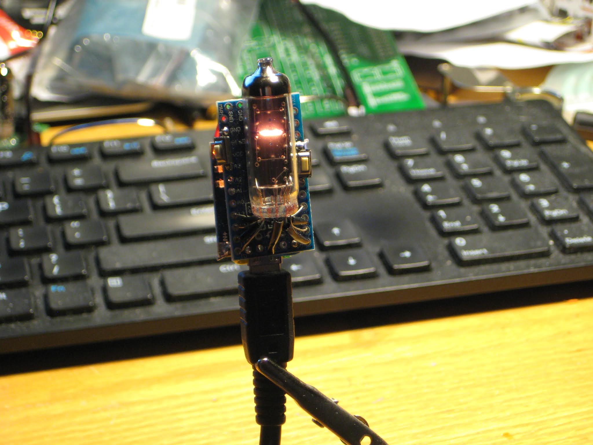
I recently found, at the bottom of a drawer, my forgotten numitron single-tube clock. It has a LiPo battery which still lights up the filaments, but no RTC to actually show time. It has a single button, which activates the display (numitron tube) when pressed. Indeed, some digits flash on, but inconsistently. And, as a clock, one would want to be able to also set the time, which is definitely not possible in this current version.
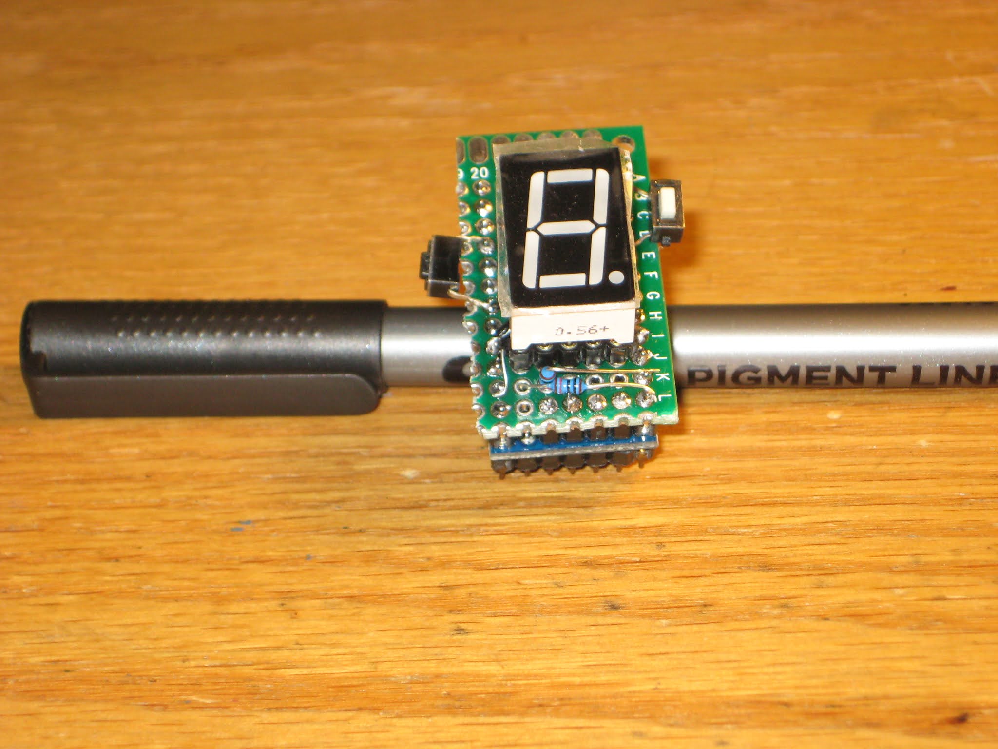
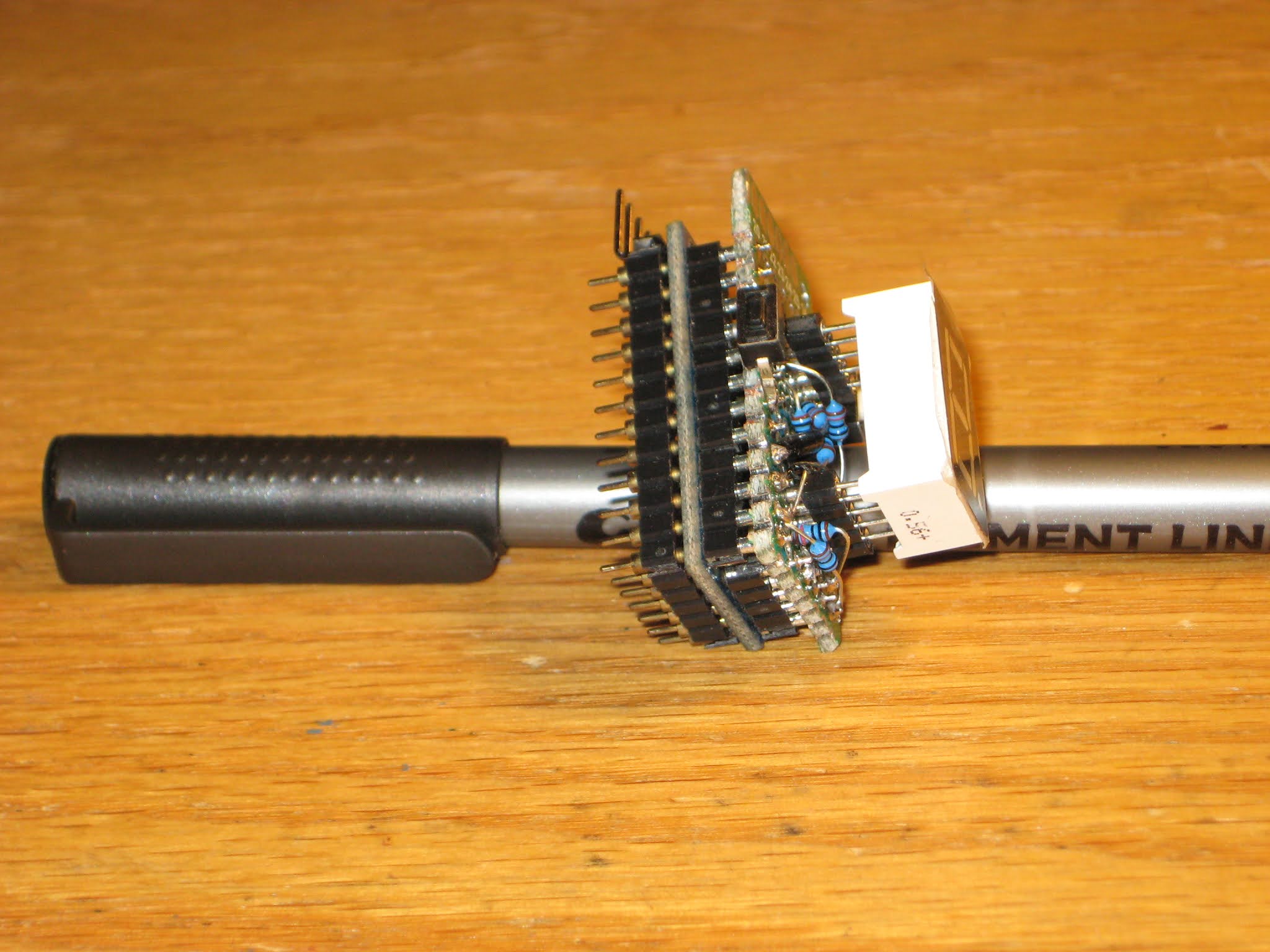
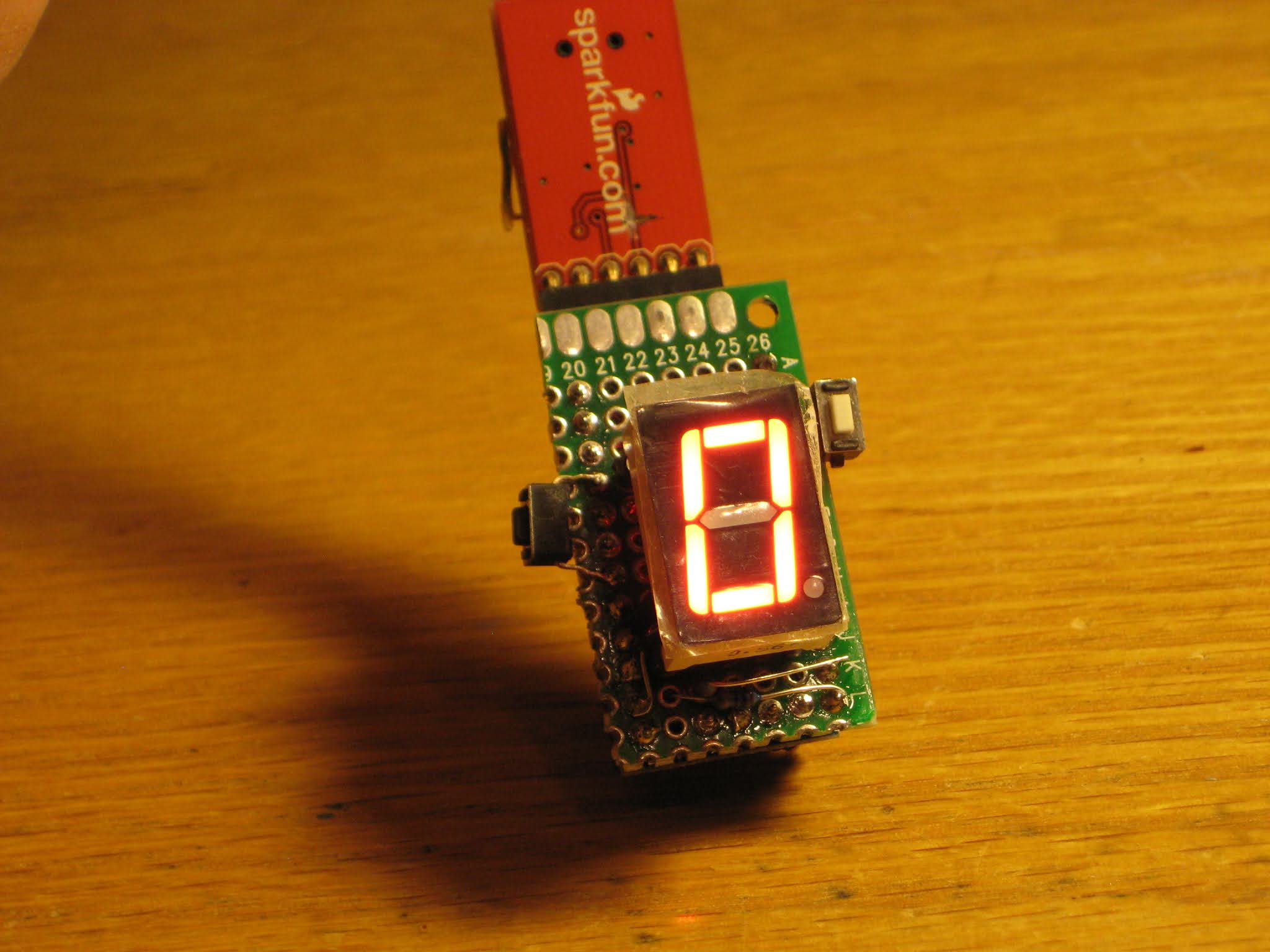
The required revision consists in:
- adding RTC
- adding a second button
- updating the software (by adding the ability to set the time through buttons)
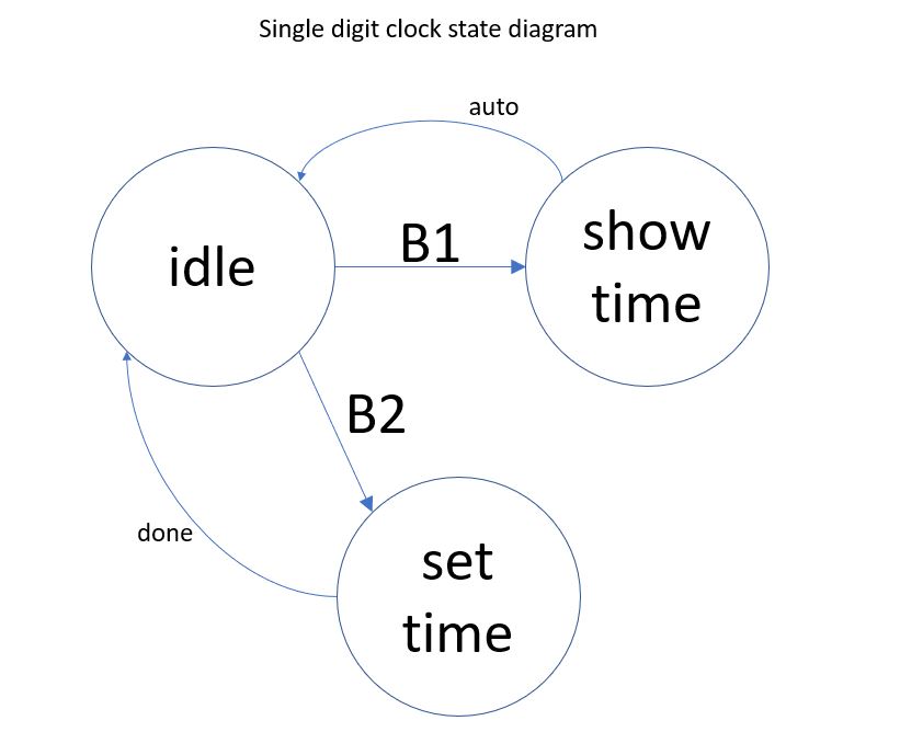
The method I devised for setting up the time follows this state-machine diagram,
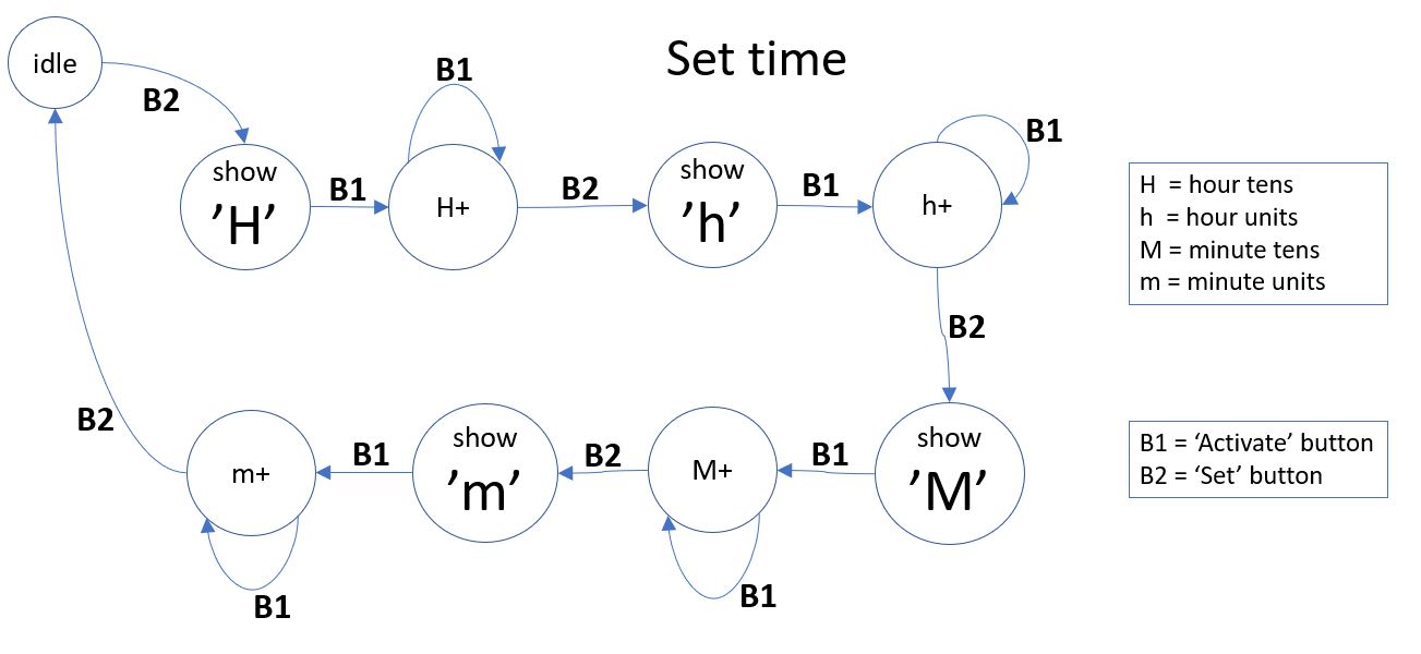
where "Set time" state is part of this bigger picture:
The whole source code file is proudly presented below (as answer to the lots of questions in the above mentioned old post).
/*************************************************************************
* Sketch for direct driving 7-segment numitron IV-9
*
* Segments are defined as follows:
*
*      A
*     ---
*  B |   | C
*     ---  D
*  E |   | F
*     ---
*      G
*
* Decimal point/comma is segment H.
* Common pin is wired to Vcc (would be nice to wire it to D11/MOSI
*      instead, which is also PWM (for brightness)).
* To light up a segment, just connect it to GND.
*
* To display a digit, ground these Arduino pins:
*   0: 6, 7, 8, 10, 11, 13
*   1: 7, 8
*   2: 6, 8, 10, 11, 12
*   3: 6, 7, 8, 11, 12
*   4: 7, 8, 12, 13
*   5: 6, 7, 11, 12, 13
*   6: 6, 7, 10, 11, 12, 13
*   7: 6, 7, 8
*   8: 6, 7, 8, 10, 11, 12, 13
*   9: 6, 7, 8, 11, 12, 13
*
*************************************************************************/

#include <Arduino.h>
#include <Wire.h>
#include "DS1307.h"

#define _DEBUG_

// arduino pins connected to tube terminals;
// chosen based on the natural positioning of the Numitron tube on Pro Mini board;
#define segA  6  	// tube pin 5
#define segB  13	// tube pin 6
#define segC  8  	// tube pin 3
#define segD  12	// tube pin 7
#define segE  10	// tube pin 9
#define segF  7         // tube pin 4
#define segG  11	// tube pin 8
#define segH  9  	// tube pin 2

// button to initiate the setting up of the time;
#define PIN_BUTTON_SET_TIME  4   // D4

// button to activate the display or to increment the time digit;
#define PIN_BUTTON_ACTIVATE  17  // A3


byte segmentPin[8] = {segA, segB, segC, segD, segE, segF, segG};


byte digits[10][7] =
{
// A  B  C  D  E  F  G
  {0, 0, 0, 1, 0, 0, 0}, 	// 0
  {1, 1, 0, 1, 1, 0, 1}, 	// 1
  {0, 1, 0, 0, 0, 1, 0}, 	// 2
  {0, 1, 0, 0, 1, 0, 0},  	// 3
  {1, 0, 0, 0, 1, 0, 1},  	// 4
  {0, 0, 1, 0, 1, 0, 0},   	// 5
  {0, 0, 1, 0, 0, 0, 0},   	// 6
  {0, 1, 0, 1, 1, 0, 1},   	// 7
  {0, 0, 0, 0, 0, 0, 0},   	// 8
  {0, 0, 0, 0, 1, 0, 0}  	// 9
};


byte state[4][7] =
{
// A  B  C  D  E  F  G
  {1, 0, 0, 0, 0, 0, 1}, 	// H
  {1, 0, 1, 0, 0, 0, 1}, 	// h
  {0, 0, 0, 1, 0, 0, 1}, 	// M
  {1, 1, 1, 0, 0, 0, 1},  	// m
};


volatile boolean wasTimeEverSet = false;
volatile boolean showingTime    = false;
volatile boolean settingTime    = false;

byte crtIndex = 0;  // 0..3, index in array timeDigits;
byte timeDigits[4] = {0, 1, 2, 3};
int hour   = 0;
int minute = 0;
int second = 0;
byte  crtValue =  0;  // used when setting the time, one digit at a time (for HHMM);
short crtState = -1;  // used when setting the time;
boolean newState = false;


void setup()
{
#ifdef _DEBUG_
  Serial.begin(9600);
  Serial.println("in setup");
#endif

  // each of display's 7 segment is connected to an output;
  for (byte i=0; i<7; i++)
  {
    pinMode(segmentPin[i], OUTPUT);
  }

  // buttons to activate tube and for setting up the time;
  pinMode(PIN_BUTTON_ACTIVATE, INPUT_PULLUP);
  pinMode(PIN_BUTTON_SET_TIME, INPUT_PULLUP);

  blankDisplay();
}


void loop()
{
  if (digitalRead(PIN_BUTTON_ACTIVATE) == LOW)
  {
#ifdef _DEBUG_
    Serial.print("settingTime=");
    Serial.println(settingTime);
#endif
    delay(200);	// debouncing;

    if (settingTime)
    {
      newState = false;

      crtValue++;
      if (crtValue > 9)
          crtValue = 0;
      displayValue(crtValue);

#ifdef _DEBUG_
      Serial.print ("crtValue=");
      Serial.println(crtValue);
#endif
    }
    else
    {
      getTimeFromRTC();
      splitTime();

      // show time as (h)h-mm;
      showingTime = true;
    }
  }

  if (digitalRead(PIN_BUTTON_SET_TIME) == LOW)
  {
    delay(200);	// debouncing;

#ifdef _DEBUG_
    Serial.print("crtState=");
    Serial.println(crtState);
#endif

    if (crtState == -1)
    {
      // user is initiating setting up the time;
      settingTime = true;
    }

    if (settingTime)
    {
      newState = true;
      crtState++;
    }

#ifdef _DEBUG_
    Serial.print("settingTime=");
    Serial.println(settingTime);
#endif
  }

  if (showingTime)
  {
#ifdef _DEBUG_
    Serial.print  ("show time, digit ");
    Serial.println(crtIndex);
#endif
    if (crtIndex == 0 && timeDigits[0] == 0)
    {
      // do not show the leading 0;
    }
    else
    {
      if (crtIndex == 2)
      {
        // show the dash between hours and minutes;
        displayDash();
        // hold it for a second;
        delay(1000);
      }

      // make the digit flash (otherwise, if 2 consecutive digits are the same, you won't see a difference);
      displayDigit(crtIndex);
      // hold the digit for a second;
      delay(1000);
    }

    crtIndex++;
    if (crtIndex > 3)
    {
      showingTime = false;  // time will show again when button is pressed;
      crtIndex = 0;
      blankDisplay();
    }
  }

  if (settingTime)
  {
    if (newState)
    {
      newState = false;

      // need to save the crtValue;
      if (crtState > 0)
      {
#ifdef _DEBUG_
        Serial.print("set value ");
        Serial.print(crtValue);
        Serial.print(" at index ");
        Serial.println(crtState-1);
#endif
        timeDigits[crtState-1] = crtValue;
      }

      if (crtState > 3)
      {
        settingTime = false;
        crtState = -1;
        blankDisplay();

#ifdef _DEBUG_
        Serial.print("saving time: ");
        Serial.print(10 * timeDigits[0] + timeDigits[1]);
        Serial.print(":");
        Serial.println(10 * timeDigits[2] + timeDigits[3]);
        Serial.print("settingTime=");
        Serial.println(settingTime);
#endif
        // time is set only after all 4 digits (HhMm) were input, that is, after state "m" is left;
        setTime(10 * timeDigits[0] + timeDigits[1], 10 * timeDigits[2] + timeDigits[3], 0);
      }
      else
      {
        displayCrtState();  // one of the 4: H, h, M, m
        // hold it for a bit;
        delay(100);

        // start setting the value from 0;
        crtValue = 0;
      }
    }
  }
}


void displayDigit(byte index)
{
  blankDisplay();
  delay(100);

  byte digit = timeDigits[index];

  // turn on the necessary segments of the digit;
  for (byte i=0; i<7; i++)
  {
    digitalWrite(segmentPin[i], digits[digit][i]);
  }
}


void displayValue(byte crtValue)
{
  blankDisplay();
  delay(100);

  // turn on the necessary segments;
  for (byte i=0; i<7; i++)
  {
    digitalWrite(segmentPin[i], digits[crtValue][i]);
  }
}


void blankDisplay()
{
  // turn off all 7 segments;
  for (byte i=0; i<7; i++)
  {
    digitalWrite(segmentPin[i], 1);
  }
}


void displayDash()
{
  blankDisplay();
  delay(100);
  digitalWrite(segD, 0);
}


void displayCrtState()
{
#ifdef _DEBUG_
    Serial.print  ("crt state is ");
    Serial.println(crtState);
#endif

  blankDisplay();
  delay(100);

  // turn on the necessary segments of the state/letter;
  for (byte i=0; i<7; i++)
  {
    digitalWrite(segmentPin[i], state[crtState][i]);
  }
}


//**********************************************************************************
// Read the entire RTC buffer
//
void getTimeFromRTC()
{
  int rtc[7];
  RTC_DS1307.get(rtc, true);

  // check to avoid glitches;
  if (rtc[DS1307_MIN] < 60 && rtc[DS1307_HR] < 24 && rtc[DS1307_SEC] < 60)
  {
    second = rtc[DS1307_SEC];
    minute = rtc[DS1307_MIN];
    hour   = rtc[DS1307_HR];
  }
/*
  // check to avoid glitches;
  if (rtc[DS1307_YR] <= 2050 && rtc[DS1307_MTH] <= 12  && rtc[DS1307_DATE] <= 31)
  {
    day    = rtc[DS1307_DATE];
    month  = rtc[DS1307_MTH];
    year   = rtc[DS1307_YR];
  }
*/
  // The RTC may have a dead battery or may have never been initialized
  // If so, the RTC doesn't run until it is set.
  // Here we check once to see if it is running and start it if not.
  if (!wasTimeEverSet) {
    wasTimeEverSet = true;
    if (hour == 0 && minute == 0 && second == 0)
    {
      // set an arbitrary time to get the RTC going;
      setTime(10,23,45);
    }
  }

#ifdef _DEBUG_
    Serial.print("Time is ");
    Serial.print(rtc[DS1307_HR]);
    Serial.print(":");
    Serial.print(rtc[DS1307_MIN]);
    Serial.print(":");
    Serial.println(rtc[DS1307_SEC]);
#endif

}


//**********************************************************************************
//
void setTime(int hh, int mm, int ss)
{
  RTC_DS1307.stop();
  RTC_DS1307.set(DS1307_SEC,  ss);
  RTC_DS1307.set(DS1307_MIN,  mm);
  RTC_DS1307.set(DS1307_HR,   hh);
  RTC_DS1307.start();
}


void splitTime()
{
  timeDigits[0] = hour / 10;
  timeDigits[1] = hour % 10;
  timeDigits[2] = minute/10;
  timeDigits[3] = minute%10;
}

[original story: Wise time with Arduino]