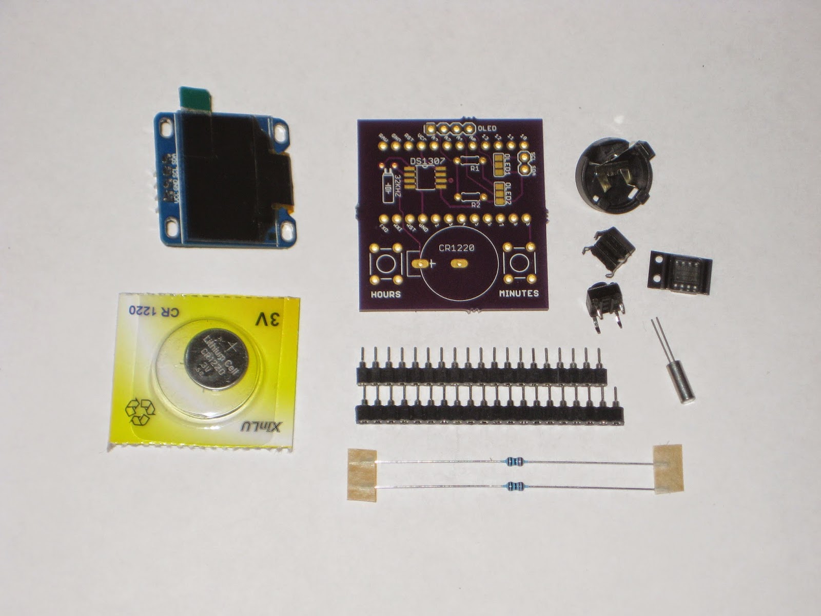
ProMini clock shield with OLED display
This is another ProMini clock shield kit, this time featuring a 128x64 I2C OLED display.

The kit can be purchased with or without the OLED display (I prefer you buy the OLED on your own, for example this excellent one from miker).
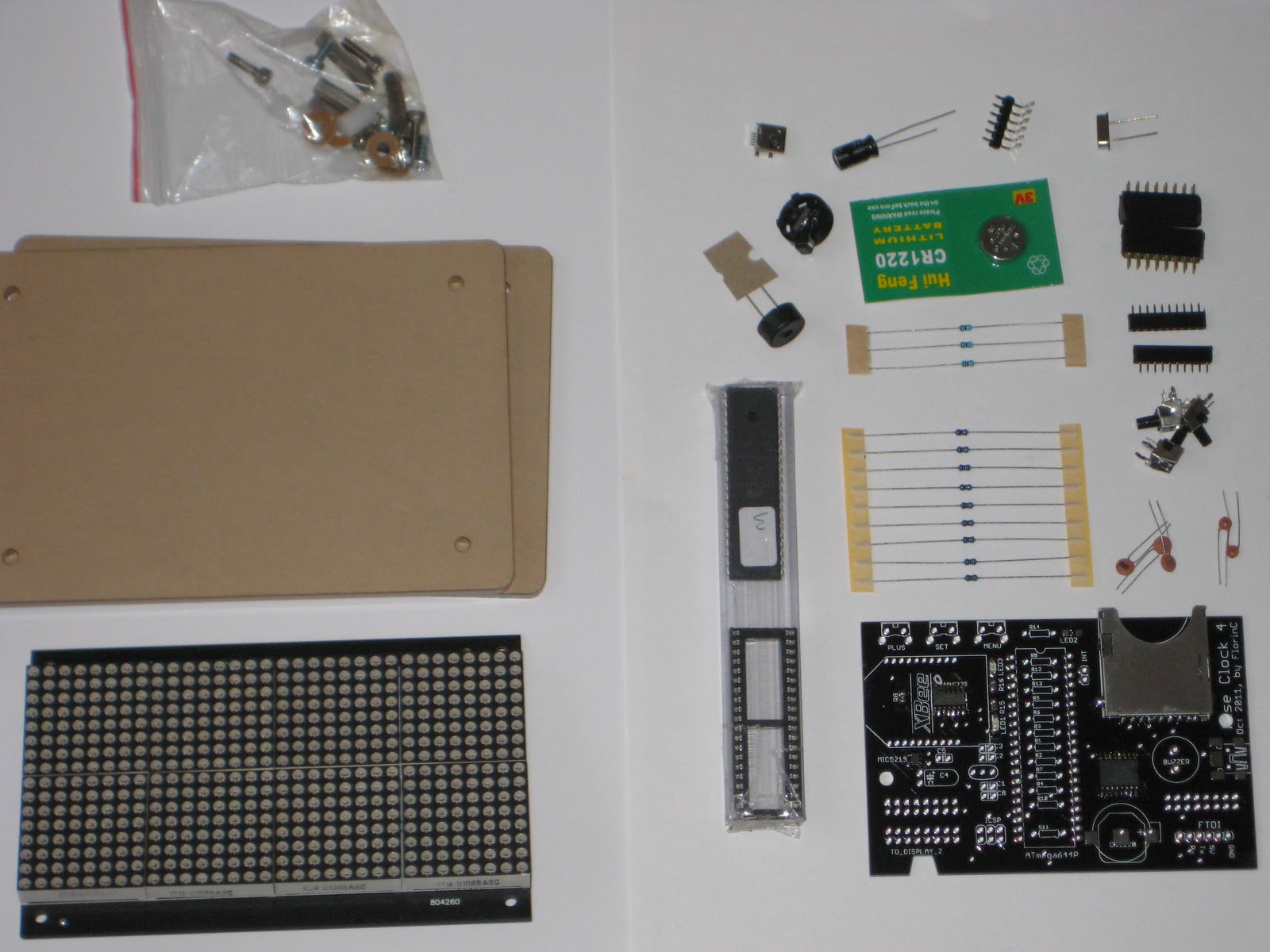
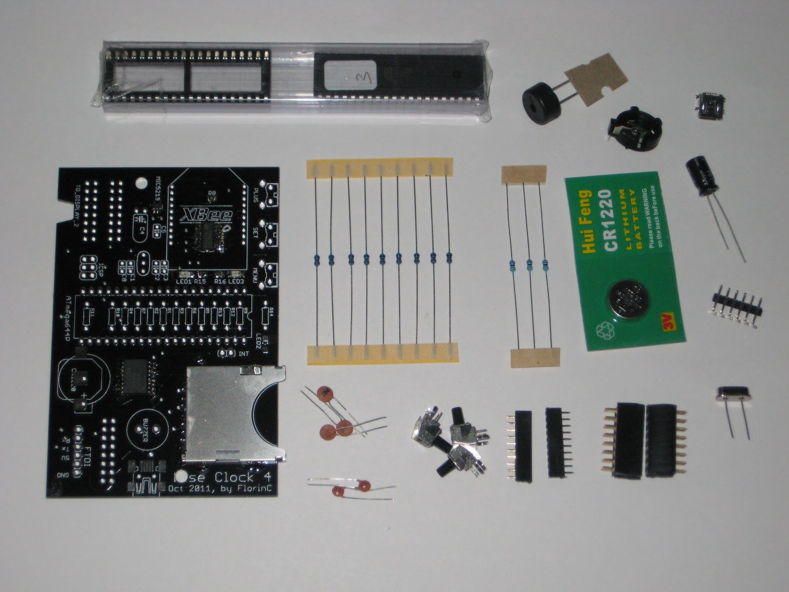
The kit includes:
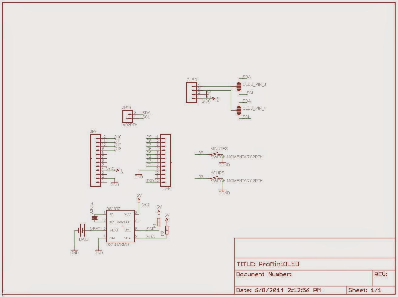
The PCB was designed to accommodate I2C OLED displays with the 4-pin header configured either as VCC-GND-SDA-SCL or as VCC-GND-SCL-SDA.
The OLED clock can also be powered from the same LiPo battery shield for ProMini, as used in the bubble clock. To minimize current consumption (beside disabling the ProMini on-board LEDs), the processor can be awaken from sleep at the push of the "hours" button (on D3).
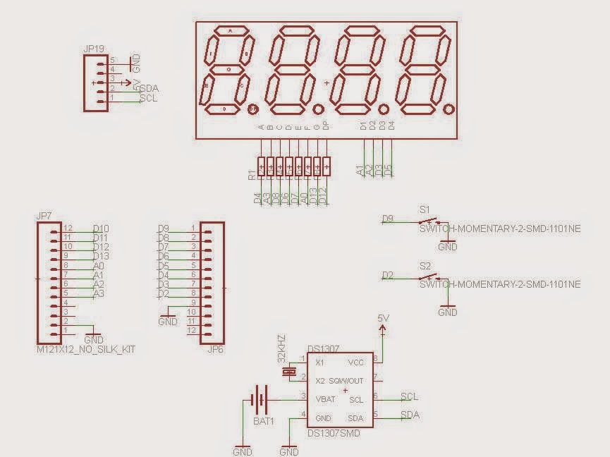
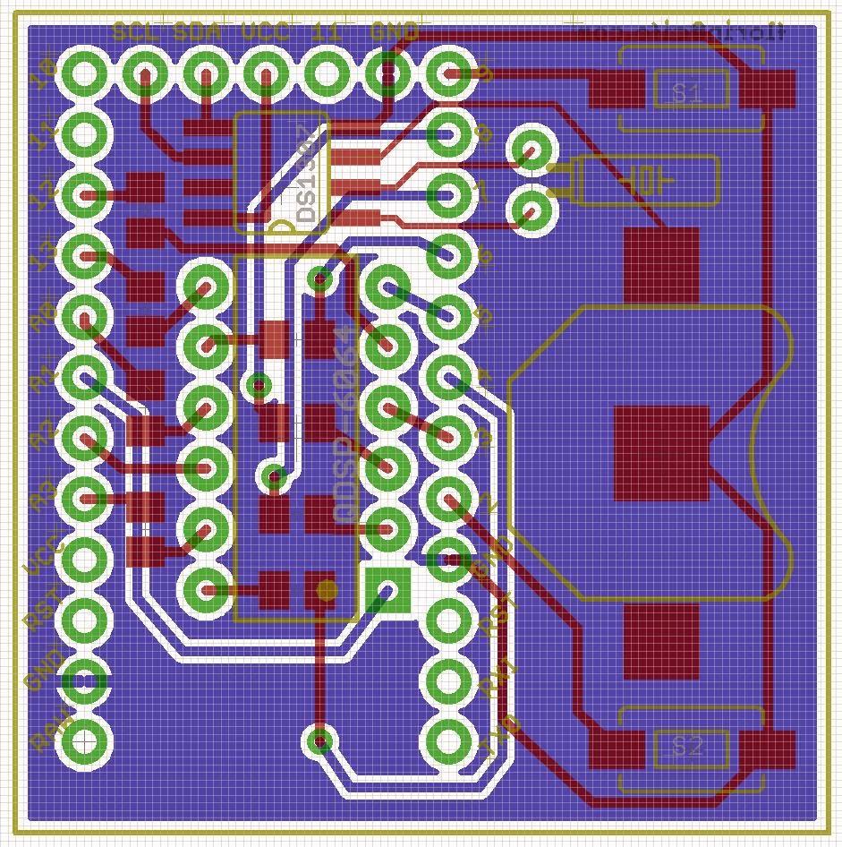
Schematic and board layout are shown below.

The OLED clock could show the time in many different ways, including Pong mode (sketch adapted from miker), analog clock mode, digital clock mode (sample sketches to be provided soon).

The kit can be purchased with or without the OLED display (I prefer you buy the OLED on your own, for example this excellent one from miker).
The kit includes:
- PCB
- DS1307 SMD
- 32kHz crystal
- CR1220 coin battery
- battery holder
- optional: I2C 128x64 OLED display (blue or white)
- tactile switch (2x)
- resistor 10k (2x)
- machined male pins
The PCB was designed to accommodate I2C OLED displays with the 4-pin header configured either as VCC-GND-SDA-SCL or as VCC-GND-SCL-SDA.
The OLED clock can also be powered from the same LiPo battery shield for ProMini, as used in the bubble clock. To minimize current consumption (beside disabling the ProMini on-board LEDs), the processor can be awaken from sleep at the push of the "hours" button (on D3).
Schematic and board layout are shown below.
The OLED clock could show the time in many different ways, including Pong mode (sketch adapted from miker), analog clock mode, digital clock mode (sample sketches to be provided soon).