Posts with «geiger» label

My review of bGeigie Nano from Safecast

I finally finished assembling, after more than a year, my bGeigie Nano. At over $400, this was by far the most expensive Arduino project I have built to date.


The feature-rich open-source Geiger counter is offered as a kit by Medcom for the price of $450 (of which, $75 is donated to Safecast organization). I stubbornly insisted on sourcing the parts on my own, to save a few bucks and to get a closer look at the process. Let me tell you: this may be the only kit out there where the components bought individually are as expensive as the kit itself! Obviously, this kit was not designed to make a profit.


Here is a price breakdown (for non-believers):
- PCB (OSHPark) - $17 (3 for $52)
- Pelican 1010 box (store) - $13
- Arduino Fio - $25
- GPS module - $40
- OpenLog - $25
- OLED display - $25
- laser-cut plates - $25
- sensor LND7317 - $150
- iRover HV supply - $35
- LiPo battery - $10
- SD card - $10
- other electronic components - $5
- hardware (standoffs, screws etc) - $5
- shipping (on some of the items) - $30
-----------------------------
Total = $415


Since it took me so long to build it, I forgot a lot of details (I know, I should have logged impressions along the way; that's why it's called "web log").
But here are a few things I can still remember:
  • the kit is pretty easy to build (once one has all components); geared towards the novice maker, the only challenge is to follow the assembly instructions, sometimes not very clear because it lacks details (for example, the spacers's sizes; although this does not matter for those who buy the kit); but it seems that the instructions are periodically updated and improved;
  • the support and discussion forum is great; I got quick and helpful answers to all my questions;
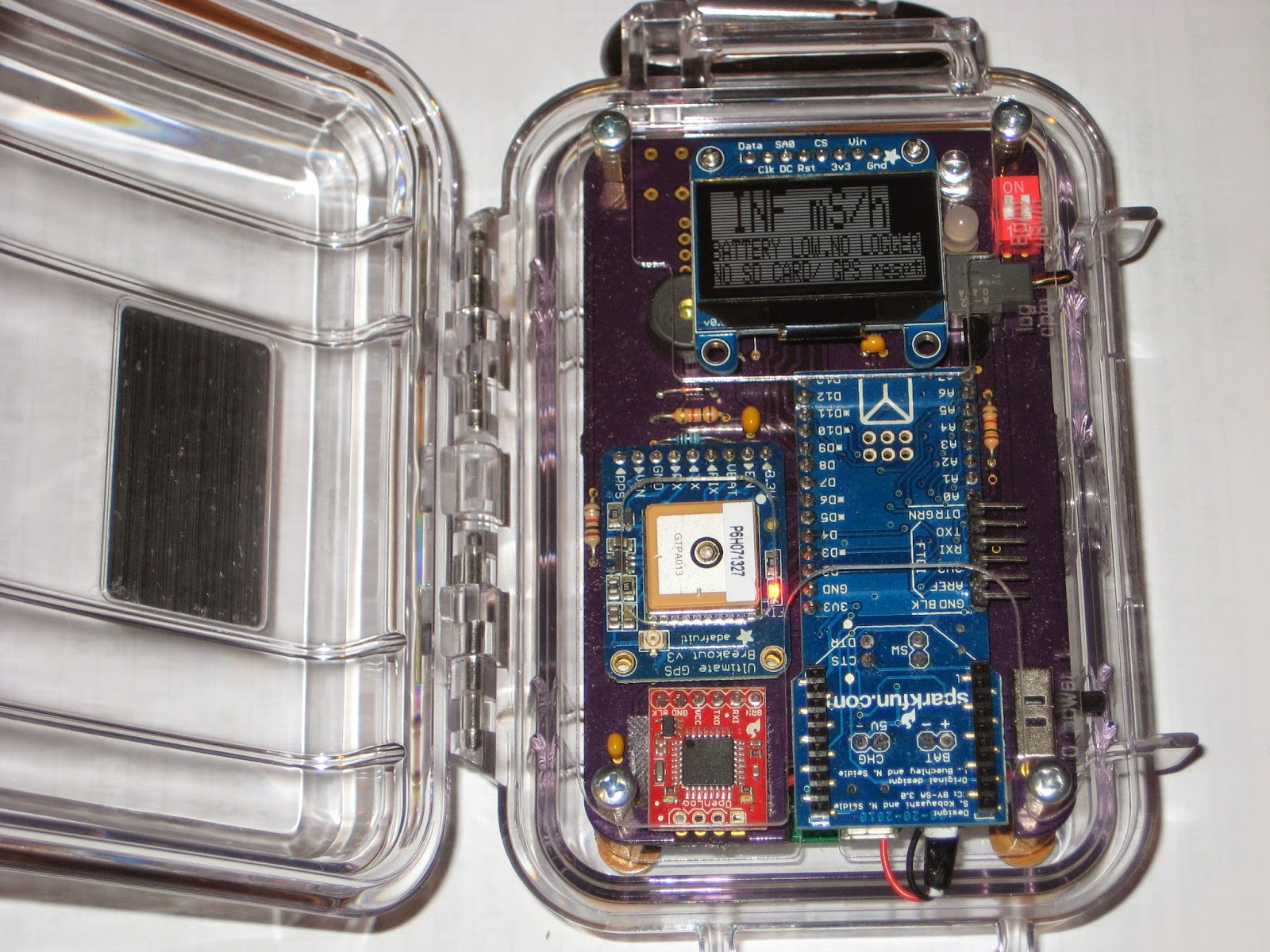
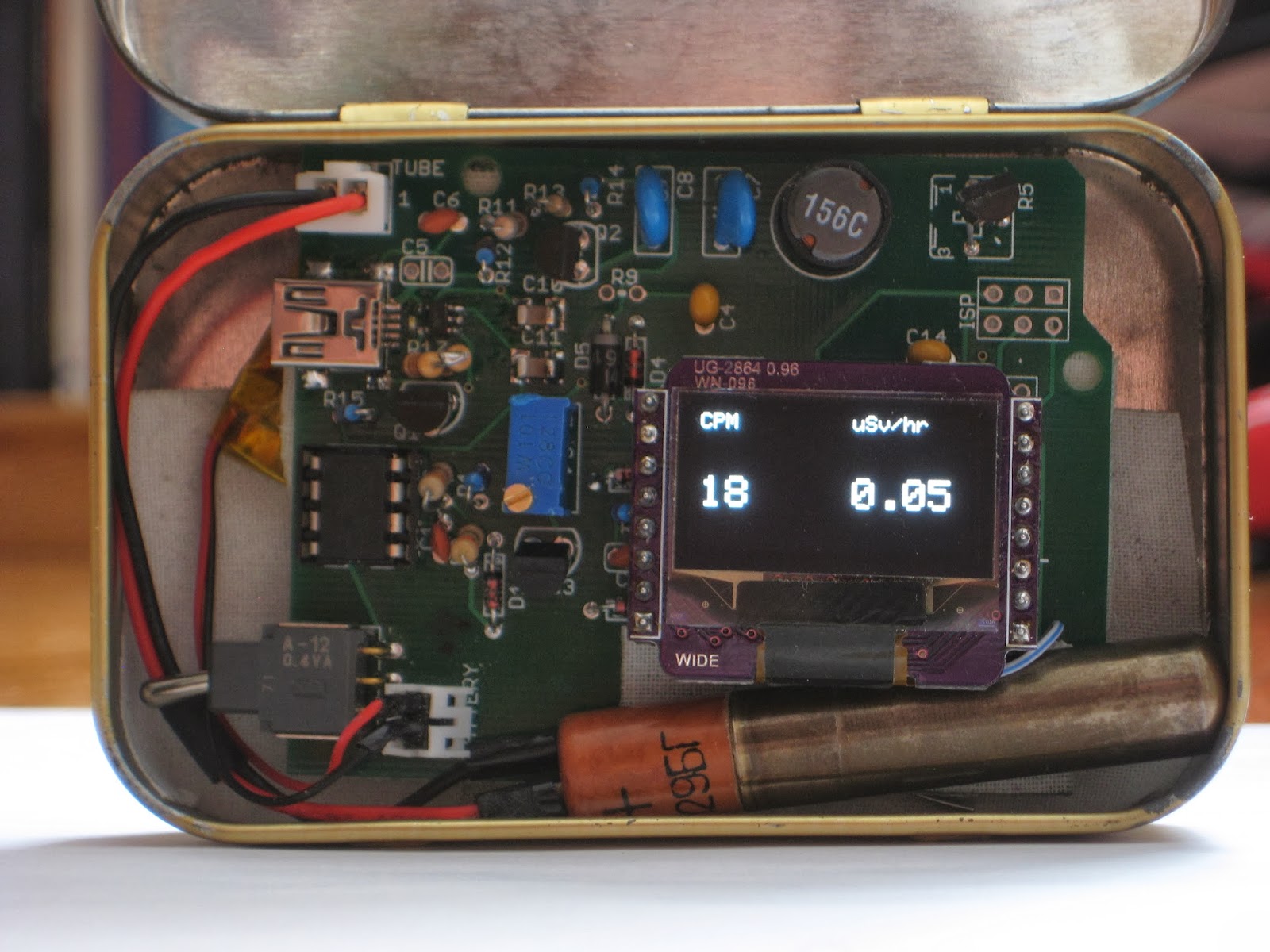
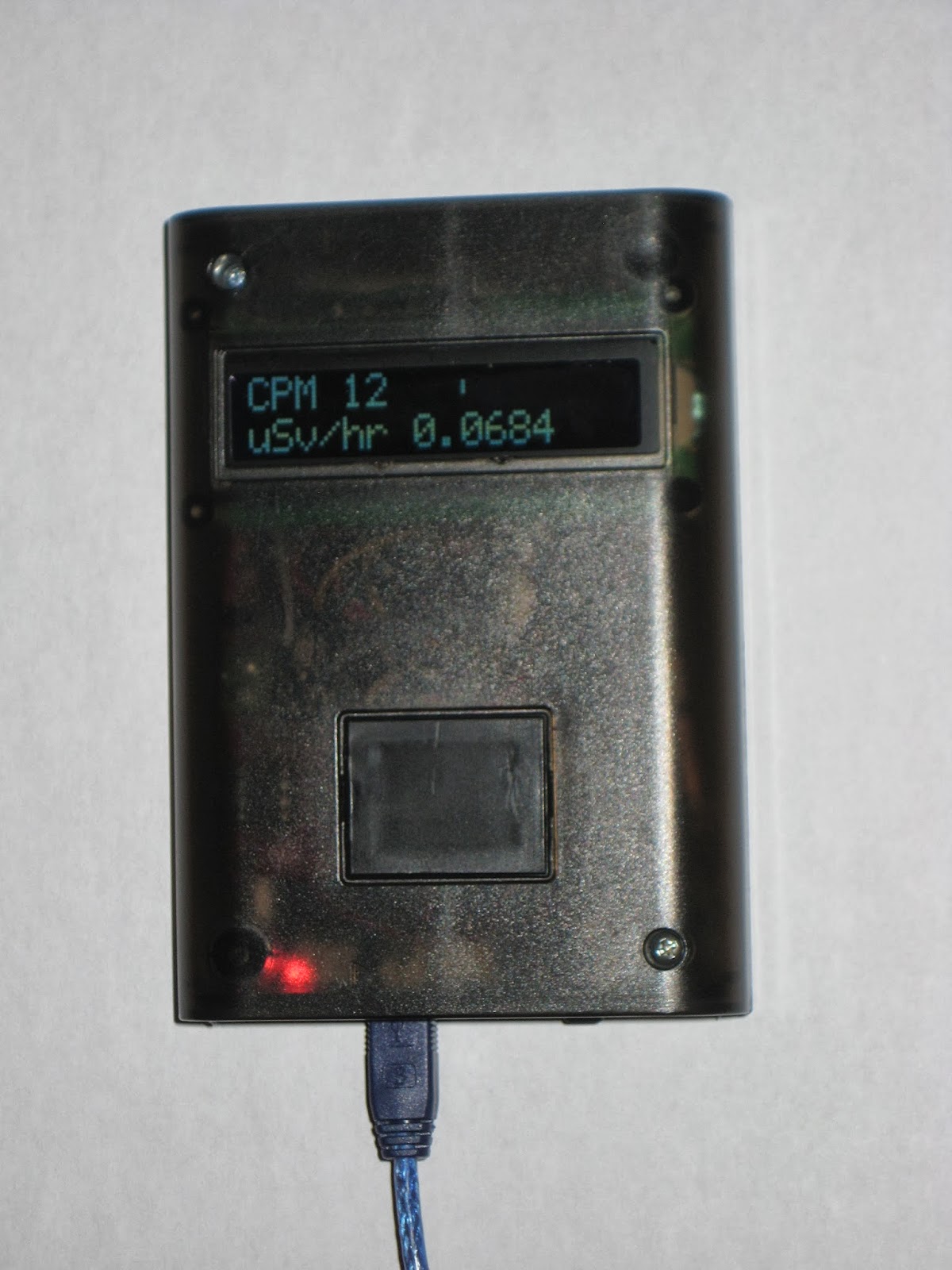
  • the display is 128x64 OLED, even though the resolution used is 128x32 (notice in the photo above that every other line is blank)
  • the sketch can barely fit in the 30KB program space of Fio's ATmega328 (I actually may have commented out some functionality to make it fit);
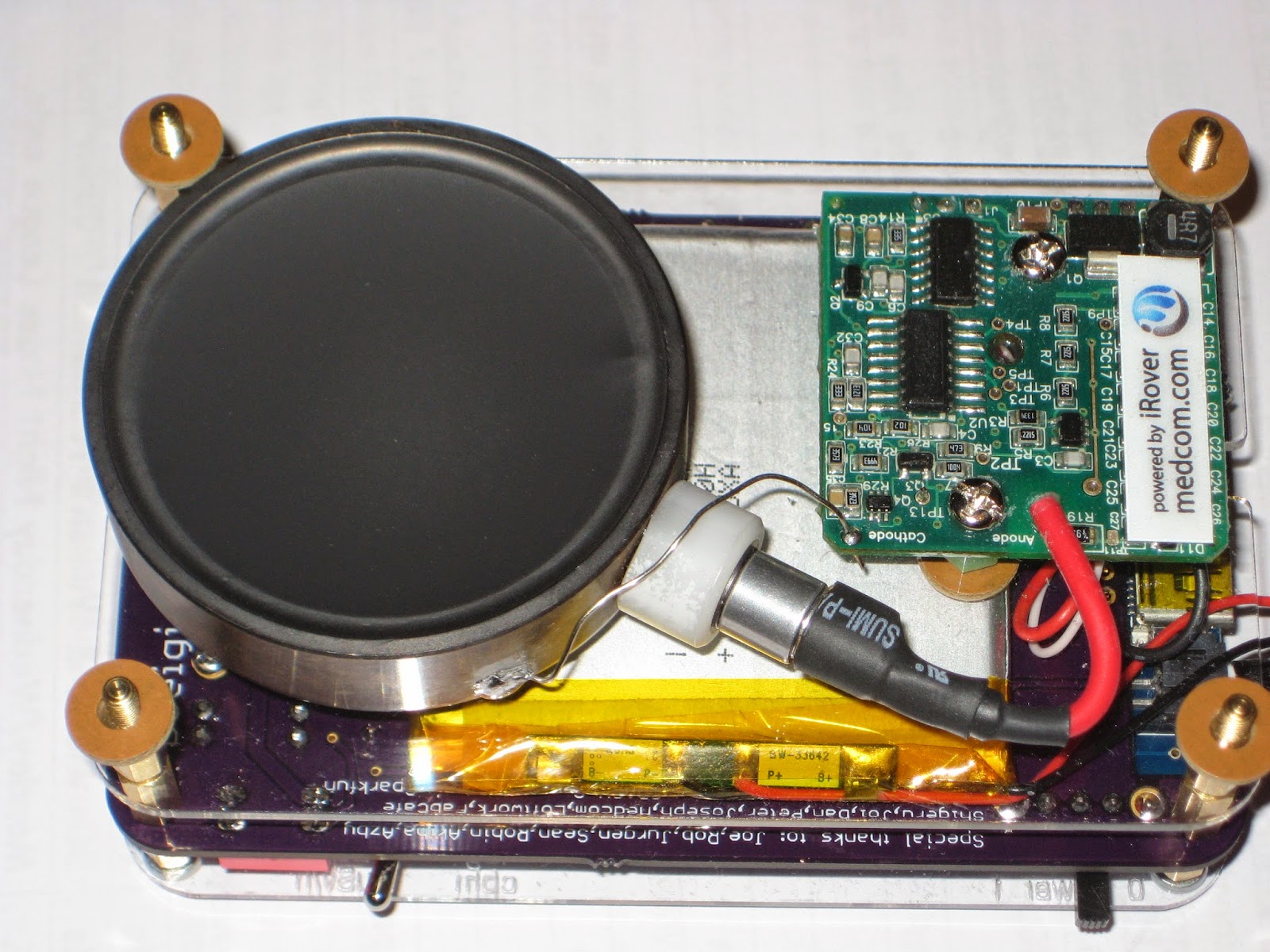
  • at the time I started, the Geiger sensor was not offered for sale (now it is); I bought it directly from Medcom, together with the high-voltage power module; they did not include the protection grid that comes with the kit;
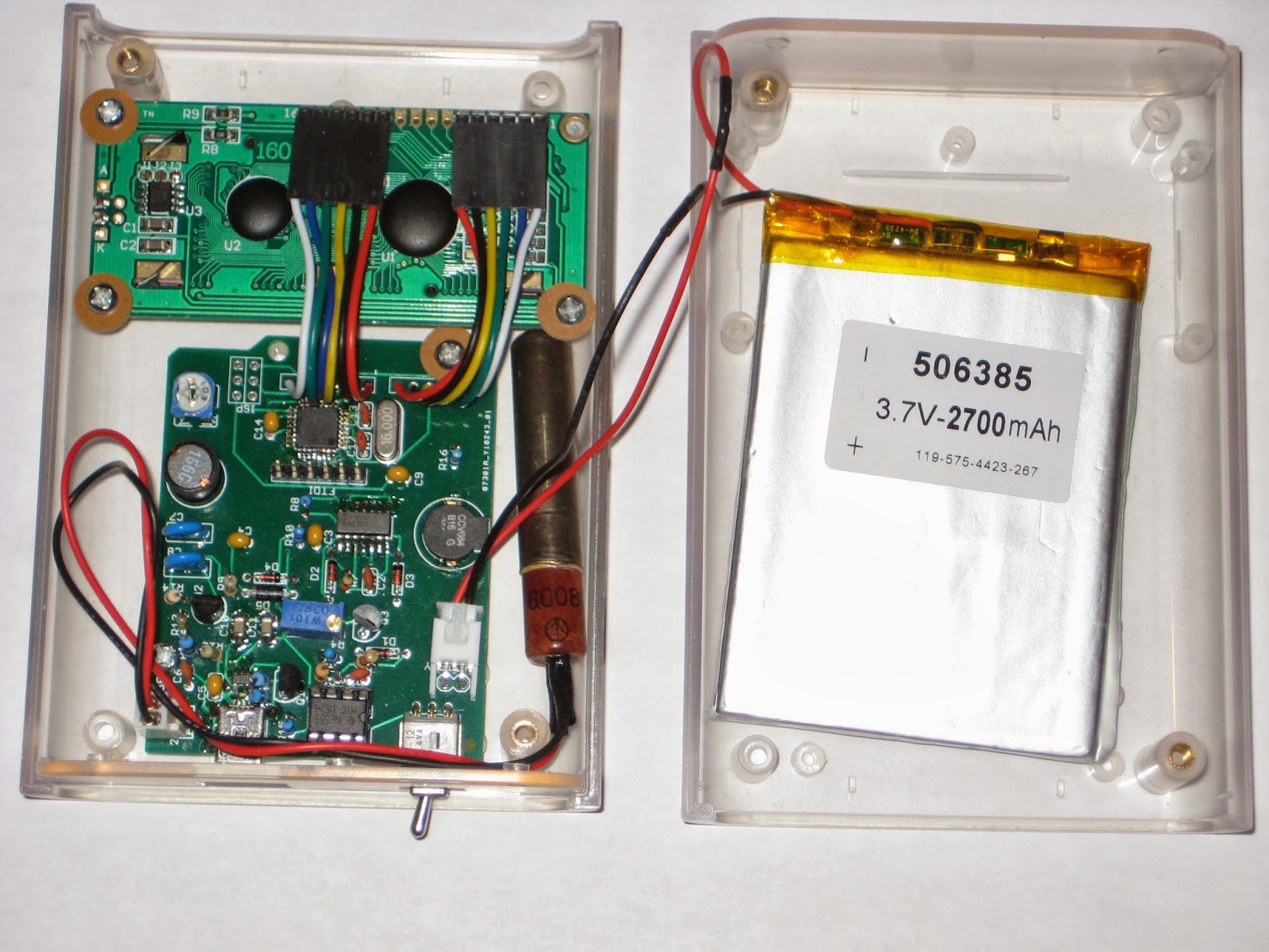
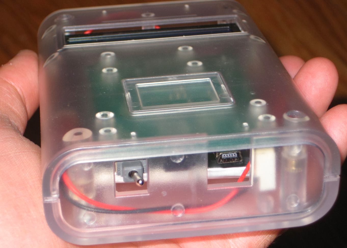
  • a big surprise was that the assembly fits perfectly in the Pelican box, without using the rubber lining (which I had cut and prepared according to the instructions anyway). When I say "perfectly" I mean nothing rattles inside when the box is shaken. Truly remarkable. For those interested, I used M3x10mm standoffs between the 1.5mm plates, with the bottom one separated with a set of 1mm washers (see photo below, taken before I installed the battery and the sensor).
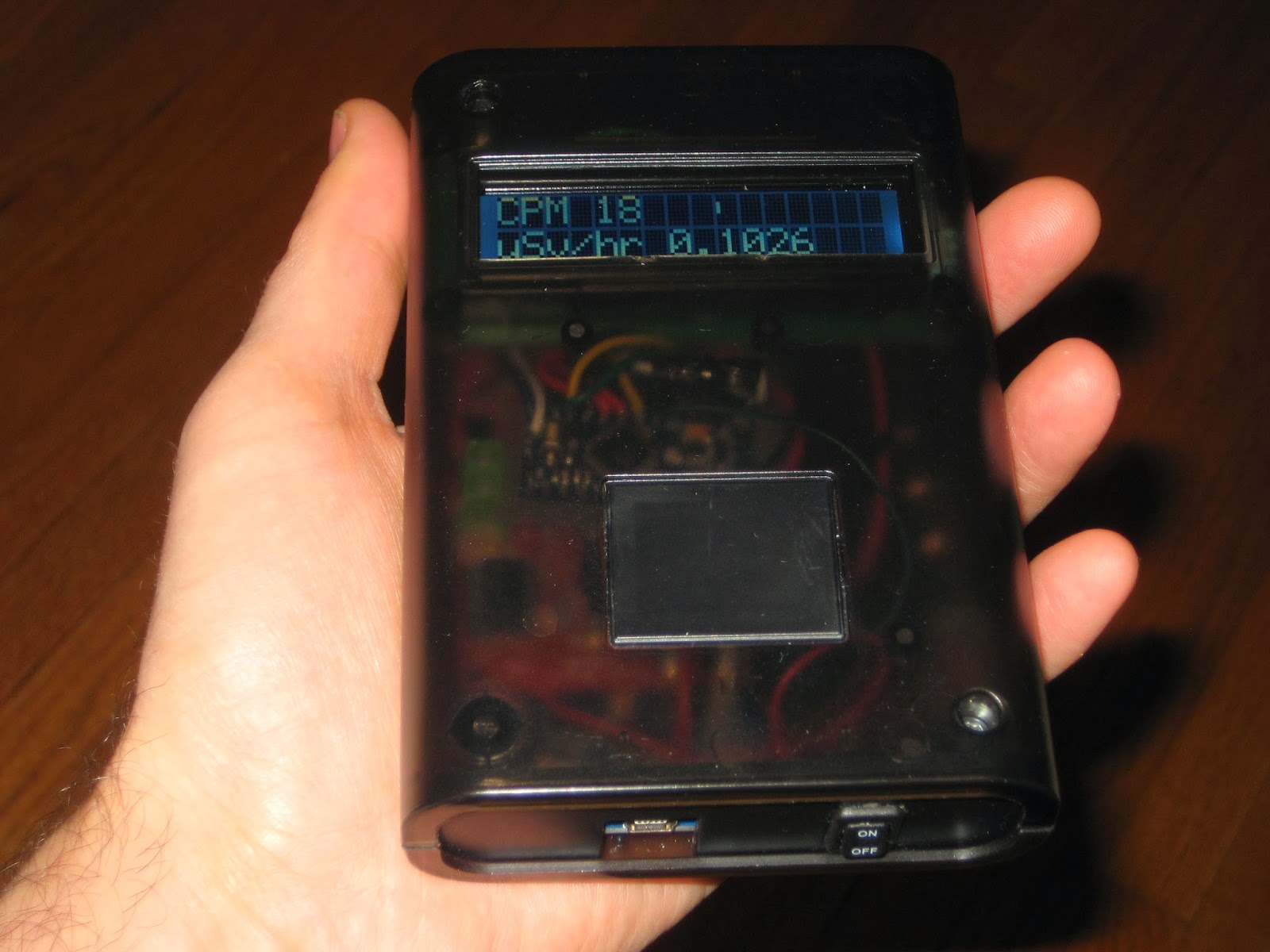
  • the toggle switch at the top would be a better candidate as power switch than the slide switch currently used; maybe a future version will swap those two switches;
  • bluetooth could be used to connect to smart phone rather than the current cable solution; but that would require a larger sketch running on a bigger processor (ATmega1284 would be a good candidate);
  • although the modules used come with headers, once installed, they cannot be removed (because they are soldered, for mechanical/space reasons; the only exception is the OLED display); removable modules would make the device easier to debug and fix (if necessary);
  • overall, it was a good experience; I used some modules for the first time; I learned a few things; it opened perspectives to new ideas; thank you guys!

Wise time with Arduino 31 May 03:48
geiger  review  

Altoids Geiger counter

My "Remixed Geiger counter" board fits almost perfectly, by chance, in the "classic" Altoids box, with room left for the SI-29 GM tube, the 1100mAh LiPo battery and the 0.96" OLED display.


The ATmega328 processor runs at 8MHz with the internal oscillator, a better choice (than the 16MHz of Arduino 2009) for the LiPo voltage of approx 3.7V.  The display I used is compatible with the monochrome 128x64 OLED display from Adafruit.
It is powered at 3V3, requiring a voltage regulator (78L33, TO-92), placed where the the trim-pot (for adjusting LCD contract) was supposed to be (top-right corner of the board).

The sketch uses Adafruit_SSD1306 library, with the wiring to the display as defined below:

#define OLED_DC 8
#define OLED_CS 7
#define OLED_CLK 4
#define OLED_MOSI 3
#define OLED_RESET 5

Note that the same D3-D8 are used for connecting to the LCD 1602 display in the "regular" DIYGeigerKit.
Also note that I did not install the "click" LED nor the buzzer, relying instead on the OLED display to indicate the radiation level.

Since the lid needs to be open anyway in order to see the screen, I thought it does not make sense to drill 2 holes in the box for the USB miniB connector (used for charging the battery) and the on/off switch. (As well, this sounds like a believable excuse for being lazy.)


If I were to improve on it, I would replace the right-angle toggle switch with a straight-up one (easier to operate), then add a button or two for user inputs (configuration parameters, menu navigation etc). The "click" buzzer and the LED could be made "digital", wired to controller's outputs. Adding a Bluetooth module would be also useful (if it works at all from inside the closed box, I need to try it). Ideally, I would also add RTC, GPS and SD card, for logging purposes. And then it would become a smaller and cheaper version of Safecast bGeigieNano :)


Wise time with Arduino 08 Feb 23:18
geiger  

Geiger Counter remixed

One of the requirements I consider important when designing a device is the ability to repair it, in case it breaks down. This means that the device should be easy to dis-assemble into its components, ideally without using a soldering iron. To achieve this goal, I usually tend to use headers and sockets for connecting the boards between them. I also try to place the buttons/switches etc. directly on the board, eventually sticking out through holes in the panel, rather than using their panel-mount equivalents connected to the board with wires.

The main reason I called one of my latest device "ugly" in a recent post was because I could not meet this requirement (well, I did not design the whole thing either). Essentially, that particular Geiger counter is very difficult to fix. Accessing to the FTDI header to re-program the Arduino Mini is also challenging. If, for some reason, the LiPo charger breaks down, the replacement miniature board would require drilling, then trace-cutting, then some wires to be soldered to the traces. I would rather throw it away then go through the (still undocumented) exercise again.

Considering all of the above, I designed a Geiger counter board shaped and dimensioned as the original Arduino, so it can fit in the Arduino enclosure from Adafruit, together with the 16x2 LCD display. The schematic is based on BroHogan's DIYGeigerCounter, to which I added the LiPo charger (with USB miniB socket) and a toggle switch for power on/off.


It does not get much simpler than this. The Geiger counter board is screwed to the half case, together with the display. With the case closed, the "free-floating" Geiger tube and the LiPo battery are held in place pretty well without additional fasteners, just by being pressed against each other.


There are 2 LEDs soldered to the bottom side of the PCB: one indicates LiPo charging, the other is the radiation indicator. This being another reason the enclosure needs to be transparent or translucent (it's not only for showing off the simple yet elegant internals :).

The 3V3 LCD display is connected to the board with a pair of 6-wire ribbon cable which can be easily unplugged if necessary. Sketches are uploaded to the ATmega328 (SMD) through the 6-pin FTDI connector, from Arduino IDE (as a matter of fact, I uploaded the release 10.2 of the DIYGeigerCounter software by BroHogan).

There is enough room in the enclosure to fit a second SI-29 Geiger tube in parallel (electrically) with the existing one, for better sensitivity.
The counter works perfectly with the bigger SBM-20 tube as well, but it is a bit challenging to fit that inside without some compromises.

The bottom cover of the enclosure does not require any modification (e.g. filing, drilling); one opening is still used for the (now smaller) USB connector, the other (originally designed for the power jack) is re-purposed for the power toggle switch.


Note that the miniB USB connector is only used for charging the battery and not for uploading sketches or for USB serial communication.

It would be very nice if this stylish enclosure gets re-designed for the 128x64 OLED display.

Wise time with Arduino 23 Jan 02:39
geiger  

The ugliest project I've built so far

Based on this photo from BroHogan's gallery of Geiger counters, it was supposed to be a simple encasing using Adafruit's Arduino enclosure. Everything looked neat and clean inside, even with room to spare.
I wanted to use LiPo instead of AAA batteries, to avoid opening and closing the device every so often. This required the use of a LiPo charger, for which I picked the one I already had, the seeedstudio's LiPo Rider.

I spent countless hours trying to put this puzzle together:
  • only 4 places for screws;
  • small(ish) charger board must to be solidly anchored to the case (since an USB cable will be plugged in frequently), yet it does not have any hole for screws;
  • 6 wires (battery, V out, switch) must be soldered to the charger SMD board;
  • 12 wires need to connect the Geiger board to the LCD, on the other half of the case;
  • trim pot suspended somewhere (since there is no room for it on the PCB);
  • power switch to fit in the rectangular opening of the bottom ;

When I thought I figured it out, the two halves of the case wouldn't close because things inside were too tall/thick. Back to the "drawing board". Took out the ATmega328 from the Geiger board (it was touching the LCD connectors, which were already minimized for space), and replaced it with a cheap ($4) "Arduino Nano" (or is it "Mini") from ebay. This also helped immensely with the wiring: instead of connecting 12 wires between the case halves (Atmega328 to LCD), I had to solder only 3 (Vcc, Gnd, Int).


After a few more kludges (e.g. re-positioned the inductor on its side, removed the (over)power(ing) LED on Arduino Nano), I ended up with something , as the saying goes, "only a mother can love".

The lesson I learned from this experience is that, if one wants a seamless, solid, beautiful, project, one needs to either design the board for an enclosure, or the enclosure for a board. Trying to mix and match the board with the enclosure leads, at best, to something ugly.


Did I mention that I worked on it on and off for about 3 months?
The red light in the bottom left corner is the "charging" LED. (And then there is the somehow annoying LCD's backlight, visible through the translucent enclosure.)


The power switch is advertised as being the smallest rocker power switch out there. I only had to file off about 1mm on the upper side of the original rectangular opening to make it fit.

Another lesson I learned: use a transparent enclosure only when the inside looks perfect and you want to show it, and by "perfect" I mean even no visible wires.

Stay tuned for the next version of this Geiger device. (You did not think I would stop here, did you ? :)

High voltage power sources for tubes (Nixie, VFD, Geiger)

This is a superficial review of the few schematics I encountered while building Nixie clocks, VFD clocks and Geiger counters (no tube amplifier just yet). Although the schematics seemed basic at a glance, they usually ended up being a challenge (that is, they rarely worked right away) for me. That's another reason I am trying to cover them here, so I can use this post as consolidated reference any time I need it.

Tubes require high voltage to work. Some (Vacuum Fluorescent Display) need 40V, others (Nixie) 180-200V, and some others (Geiger) even higher, 400-1000V. The high voltages are generated these days by switching-mode power supplies. Essentially, there is only a handful of popular solutions, and each DIY tube kit picks one of these, based on size, power requirements, cost.

In principle, a switching mode power supply, also known as "boost converter", uses a square wave oscillator ("switch") to create magnetic energy in an inductor, then releasing it as high voltage.
Some scientific explanation (with formulas) can be found here, some practical advice (with schematics and photos) here. Adafruit has a very useful online boost calculator.

1. One of the most popular solution for the square wave oscillator is by using the ubiquitous 555. This is inexpensive, but requires some tweaking and adjusting (values of resistors and capacitors). The schematic is standard, but there seem to be a few variations.
The one below is from Ronald Dekker.


Frank clock (from Pete's Nixie kits) uses an almost identical schematic, but a different set of values for R2-R3- C4 (used for setting the frequency). In the end, the oscillator frequency is about the same at approx 30kHz, calculated with formula  f = 1/0.693/C4/(R3+2R2)  (in the schematic below).


Same 555 is used in Arduinix, but in a different configuration, although still as astable oscillator. This one has an extra HV capacitor (C4) in series with a resistor (R15), whose exact purpose I don't understand. The oscillation frequency is also weird, according to the above formula, with C3 at 47pF, should be 1.5kHz. No wonder this did not work for me.


Another almost identical HV power supply for Nixie tubes is used in the recently-kickstarted "Nixie tube shield" (for which I pledged $15 for the PCB, and yet to receive it).


And finally, 555 is also used to generate the higher voltages required by Geiger tubes, as used by BroHogan (and MightyOhm). The frequency of oscillation is 4.5kHz (f = 1/R1/C2). (I built several Geiger kits from BroHogan and they were all trouble-free.)


2. Other solutions use specialized chips like MAX1771 and MC34063.
Shown below is the high-efficiency boost converter from Nick de Smith (sold by ogiLumen), based on MAX1771.


Akafugu's VFD Version 1 clock uses the same MAX1771, to generate a lower 50V (for VFD tubes).


For MK2, Akafugu switched to using MC34063 chip (schematic not published yet).
The same chip is also used in their Nixie clock (schematic shown below), to generate 180V. This HV circuit has its own (all SMD) board, which I assembled it myself and worked without a glitch.


3. Yet others use a PWM pin of a microcontroller. This method requires the processor to be connected and programmed in order to generate the high voltage. The solution is cheap (saves an extra chip), smaller in size (again, one less chip), and also seems to be highly efficient.

Below is the HV schematic used by Adafruit's IceTube clock.


Some of the microcontroller-based boost converters have feedback (close loop, with PWM adjusting to the voltage output, if I am not mistaken), as are those from Cogwheel and Satashnik (shown below, respectively).


As with any analog electronics circuit, troubleshooting a HV supply is not easy. A suitable tool would be an oscilloscope, allowing for the measurement and adjustment of the frequency and pulse width. Once these are cleared, the high voltage could be adjusted usually from the trim pot. To modify the voltage range, try different values for the inductor.

Wise time with Arduino 05 Oct 08:57
geiger  general  nixie