Posts with «hall effect» label

The Seven-Segment Display That’s Also an Input Device

We’re used to seeing all manner of seven-segment displays, be they mechanical, electronic, or something in between. But what all these displays have in common is that they’re, you know, displays. Using them as inputs would just be crazy talk, right?

Perhaps, but we like where [Dave Ehnebuske] is going with “InSlide,” the seven-segment input device. The idea for this comes from the “DigiTag” display, which we covered back in October, and divides a standard seven-segment character into three vertical strips — two skinny ones for the outside vertical segments, and one wide strip holding the horizontal elements. By sliding these strips up and down relative to each other, the standard nine digits, plus a few other characters, can be composed.

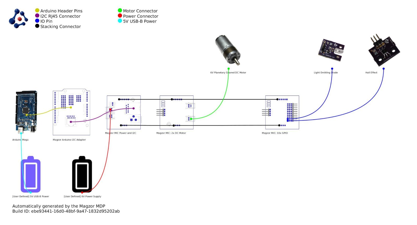
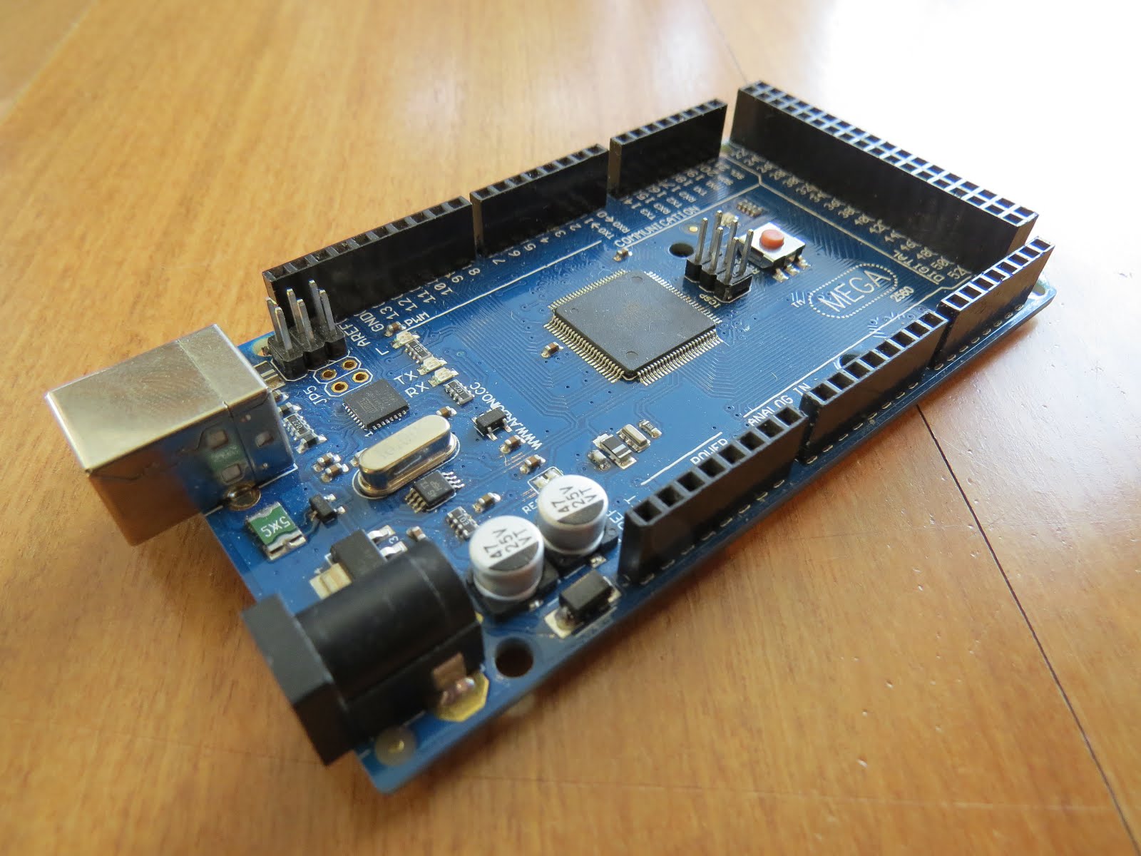
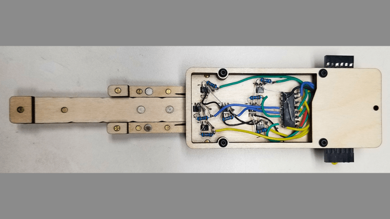
[Dave]’s take on this theme started by building his display from laser-cut plywood pieces, which is a nice choice because of the good contrast between the white wood and the engraver segments. Next, he embedded rare earth magnets in the slides and installed seven Hall effect sensors in the frame. The sensors are connected to an Arduino Nano via a 74HC165 parallel-load shift register, which lets multiple modules be daisy-chained together. He also built an Arduino library to read the current state of the segments; it supports the full hexadecimal character set, or even duodecimal if you like.

[Dave] has shared the library, and it looks like you can get the build files for the mechanism from the original project. That’s good, because this looks ripe for hacking. It looks like it would be pretty easy to motorize a display like this by adding rack-and-pinion gearing and steppers — something like that could make an interesting clock.

TMD-1 Makes Turing Machine Concepts Easy to Understand

For something that has been around since the 1930s and is so foundational to computer science, you’d think that the Turing machine, an abstraction for mechanical computation, would be easily understood. Making the abstract concepts easy to understand is what this Turning machine demonstrator aims to do.

The TMD-1 is a project that’s something of a departure from [Michael Gardi]’s usual fare, which has mostly been carefully crafted recreations of artifacts from the early days of computer history, like the Minivac 601  trainer and the DEC H-500 computer lab. The TMD-1 is, rather, a device that makes the principles of a Turing machine more concrete. To represent the concept of the “tape”, [Mike] used eight servo-controlled flip tiles. The “head” of the machine conceptually moves along the tape, its current position indicated by a lighted arrow while reading the status of the cell above it by polling the position of the servo.

Below the tape and head panel is the finite state machine through which the TMD-1 is programmed. [Mike] limited the machine to three states and four transitions, each of which is programmed by placing 3D-printed tiles on a matrix. Magnets were inserted into cavities during printing; Hall Effect sensors in the PCB below the matrix read the pattern of magnets to determine which tiles are where. The video below shows the TMD-1 counting from 0 to 10, which is enough to demonstrate the basics of Turing machines.

It’s hard not to comment on the irony of a Turing machine being run by an Arduino, but given that [Mike]’s goal was to make abstract concepts easy to understand, it makes perfect sense to leverage the platform rather than try to do this with discrete logic. And you can’t argue with results — TMD-1 made Turing machines clear to us for the first time.

Flying the Friendly Skies with A Hall Effect Joystick

There are plenty of PC joysticks out there, but that didn’t stop [dizekat] from building his own. Most joysticks mechanically potentiometers or encoders to measure position. Only a few high-end models use Hall effect sensors. That’s the route [dizekat] took.

Hall effect sensors are non-contact devices which measure magnetic fields. They can be used to measure the position and orientation of a magnet. That’s exactly how [dizekat] is using a trio of sensors in his design. The core of the joystick is a universal joint from an old R/C car. The center section of the joint (called a spider) has two one millimeter thick disc magnets glued to it. The Hall sensors themselves are mounted in the universal itself. [Dizekat] used a small piece of a chopstick to hold the sensors in position while he found the zero point and glued them in. A third Hall effect sensor is used to measure a throttle stick positioned on the side of the box.

An Arduino micro reads the sensors and converts the analog signal to USB.  The Arduino Joystick Library by [Matthew Heironimus] formats the data into something a PC can understand.

While this is definitely a rough work in progress, we’re excited by how much [dizekat] has accomplished with simple hand tools and glue. You don’t need a 3D printer, laser cutter, and a CNC to pull off an awesome hack!

If you think Hall effect sensors are just for joysticks, you’d be wrong – they work as cameras for imaging magnetic fields too!

Hack a Day 18 Jan 09:00

Arduino + Geometry + Bicycle = Speedometer

It is pretty easy to go to a big box store and get a digital speedometer for your bike. Not only is that no fun, but the little digital display isn’t going to win you any hacker cred. [AlexGyver] has the answer. Using an Arduino and a servo he built a classic needle speedometer for his bike. It also has a digital display and uses a hall effect sensor to pick up the wheel speed. You can see a video of the project below.

[Alex] talks about the geometry involved, in case your high school math is well into your rear view mirror. The circumference of the wheel is the distance you’ll travel in one revolution. If you know the distance and you know the time, you know the speed and the rest is just conversions to get a numerical speed into an angle on the servo motor. The code is out on GitHub.

Granted, reading a magnet, keeping time, and driving a servo isn’t exactly cutting edge. On the other hand, it made us think about what other kinds of outputs you could drive. We haven’t seen a nixie tube speedometer (well, not on a bicycle, anyway), for example. Or maybe one built with mechanical flip numbers like an old clock.

We have seen some with Arduinos and lots of LEDs (although, again, not really for a bicycle). This speedometer might still be our favorite, though.


Filed under: Arduino Hacks, transportation hacks

Arduino Stroboscope Animation


UPDATE: Magzor has just started a Kickstarter campaign. Please check it out to get a good package deal on many of their components. Many of which were used in this tutorial.
 
This tutorial will show you how to build your own Stroboscopic Animator using Magzor's Mechanotronic Design Portal as a starting point. Magzor Corporation is a business in California that is trying really hard to simplify robotic design. They want to enable users with little to no engineering experience to design and manufacture a custom robot by themselves in a matter of hours.
What is a stroboscope? A stroboscope is an instrument that uses a strobe light to make a moving object look stationary… We will use this feature to create an interesting 4 picture animation on a rotating disk.


Have a look at the video below to see the project in action, and the MDP process walk-through:


Video


Parts Required:


Magzor Schematic Diagram

Click to zoom ...

 
Further build instructions can be obtained by selecting the components in the Mechanotronics Design Portal within the Magzor website. Generating the build, and then selecting "Setup Instructions" tab at the top of the page. See video above to see this process in action.


Arduino Sketch


Make sure to copy and paste the following code into your Arduino IDE. It doesn't seem to work directly from the browser. You also need to install the Arduino Magzor I2C library ( http://magzor.com/downloads/ )


Putting it together


Arduino MEGA


Magzor I2C board


MIC Boards


MIC Boards Assembled


Sensors, Modules and Shields - all put together


Motor with Bracket and Wire


Picture lined up with magnet on disk


Stroboscopic Animation


The Arduino MEGA microcontroller listens for the hall effect sensor to be triggered by the south facing side of the magnet on the underside of the rotating disk. As the magnet moves over the hall effect sensor, the sensor is triggered and the Arduino instructs the LED to blink for a fraction of a second. By manipulating the delay after the trigger time, we can get the LED to blink when one of the four images on the rotating disk is towards the front position. And if we get the timing right, we can make a simple animation.
 
If you watch the video above, you will see that the image bounces around a little bit. The duration of each frame is determined by the speed of the rotating disk (or motor), and the number of LED flashes per frame. Any changes in rotation speed will affect the position of the picture when the LED blinks. My rotating disk is not completely semetrical or centred correctly, and therefore a bit jumpy… but you get the idea. Bold images with high contrast seem to work best… Precision is key for this type of project. And if you can get the disk to rotate at a constant speed, you could probably do away with the hall effect sensors and magnets… however, in my case, these were essential in getting the project to work as intended.
 
This project is a lot of fun. You can really get creative by making your own pictures or 3 dimensional models (for a stop motion effect). Try different colours. It really is quite cool.


Concluding Comments


I would like to thank Magzor for supplying the components used in this tutorial, and letting me try out their MDP process. I really like the concept, the one stop shop which looks after you from beginning to end. Providing everything I needed to get the project off the ground. The point of this exercise was to go through the entire process of selecting the parts, build the project, and get it up and running. And I have done that in no time at all.
 
There is only one library to download and install, and the good thing is that you don't have to go hunting for it. The latest "correct" working version of the library is easy to find, right there on the Magzor website… Speaking of the Magzor website, please make sure to take a quick look around. It is quite impressive.
 
  UPDATE: Magzor has just started a Kickstarter campaign. Please check it out to get a good package deal on many of their components. Many of which were used in this tutorial.


If you like this page, please do me a favour and show your appreciation :

 
Visit my ArduinoBasics Google + page.
Follow me on Twitter by looking for ScottC @ArduinoBasics.
I can also be found on Pinterest and Instagram.
Have a look at my videos on my YouTube channel.


This project would not have been possible without the collaborative effort from Magzor Corporation.
Please visit their site and check out the MDP.


However, if you do not have a google profile...
Feel free to share this page with your friends in any way you see fit.

Arduino Stroboscope Animation


This tutorial will show you how to build your own Stroboscopic Animator using Magzor's Mechanotronic Design Portal as a starting point. Magzor Corporation is a business in California that is trying really hard to simplify robotic design. They want to enable users with little to no engineering experience to design and manufacture a custom robot by themselves in a matter of hours.

What is a stroboscope? A stroboscope is an instrument that uses a strobe light to make a moving object look stationary… We will use this feature to create an interesting 4 picture animation on a rotating disk.


Have a look at the video below to see the project in action, and the MDP process walk-through:


Video


Parts Required:


Magzor Schematic Diagram

Click to zoom ...


Further build instructions can be obtained by selecting the components in the Mechanotronics Design Portal within the Magzor website. Generating the build, and then selecting "Setup Instructions" tab at the top of the page. See video above to see this process in action.


Arduino Sketch


Make sure to copy and paste the following code into your Arduino IDE. It doesn't seem to work directly from the browser. You also need to install the Arduino Magzor I2C library ( http://magzor.com/downloads/ )


Putting it together


Arduino MEGA


Magzor I2C board


MIC Boards


MIC Boards Assembled


Sensors, Modules and Shields - all put together


Motor with Bracket and Wire


Picture lined up with magnet on disk


Stroboscopic Animation


The Arduino MEGA microcontroller listens for the hall effect sensor to be triggered by the south facing side of the magnet on the underside of the rotating disk. As the magnet moves over the hall effect sensor, the sensor is triggered and the Arduino instructs the LED to blink for a fraction of a second. By manipulating the delay after the trigger time, we can get the LED to blink when one of the four images on the rotating disk is towards the front position. And if we get the timing right, we can make a simple animation.
 
If you watch the video above, you will see that the image bounces around a little bit. The duration of each frame is determined by the speed of the rotating disk (or motor), and the number of LED flashes per frame. Any changes in rotation speed will affect the position of the picture when the LED blinks. My rotating disk is not completely semetrical or centred correctly, and therefore a bit jumpy… but you get the idea. Bold images with high contrast seem to work best… Precision is key for this type of project. And if you can get the disk to rotate at a constant speed, you could probably do away with the hall effect sensors and magnets… however, in my case, these were essential in getting the project to work as intended.
 
This project is a lot of fun. You can really get creative by making your own pictures or 3 dimensional models (for a stop motion effect). Try different colours. It really is quite cool.


Concluding Comments


I would like to thank Magzor for supplying the components used in this tutorial, and letting me try out their MDP process. I really like the concept, the one stop shop which looks after you from beginning to end. Providing everything I needed to get the project off the ground. The point of this exercise was to go through the entire process of selecting the parts, build the project, and get it up and running. And I have done that in no time at all.
 
There is only one library to download and install, and the good thing is that you don't have to go hunting for it. The latest "correct" working version of the library is easy to find, right there on the Magzor website… Speaking of the Magzor website, please make sure to take a quick look around. It is quite impressive.


If you like this page, please do me a favour and show your appreciation :

 
Visit my ArduinoBasics Google + page.
Follow me on Twitter by looking for ScottC @ArduinoBasics.
I can also be found on Pinterest and Instagram.
Have a look at my videos on my YouTube channel.


This project would not have been possible without the collaborative effort from Magzor Corporation.
Please visit their site and check out the MDP.


However, if you do not have a google profile...
Feel free to share this page with your friends in any way you see fit.