Posts with «pca9685» label

Building This Mechanical Digital Clock Took Balls

In the neverending quest for unique ways to display the time, hackers will try just about anything. We’ve seen it all, or at least we thought we had, and then up popped this purely mechanical digital clock that uses nothing but steel balls to display the time. And we absolutely love it!
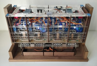
Click to embiggen (you’ll be glad you did)

One glimpse at the still images or the brief video below shows you exactly how [Eric Nguyen] managed to pull this off. Each segment of the display is made up of four 0.25″ (6.35 mm) steel balls, picked up and held in place by magnets behind the plain wood face of the clock. But the electromechanical complexity needed to accomplish that is the impressive part of the build. Each segment requires two servos, for a whopping 28 units plus one for the colon. Add to that the two heavy-duty servos needed to tilt the head and the four needed to lift the tray holding the steel balls, and the level of complexity is way up there. And yet, [Eric] still managed to make the interior, which is packed with a laser-cut acrylic skeleton, neat and presentable, as well he might since watching the insides work is pretty satisfying.

We love the level of craftsmanship and creativity on this build, congratulations to [Eric] on making his first Arduino build so hard to top. We’ve seen other mechanical digital displays before, but this one is really a work of art.

Thanks to [Ruhan van der Berg] for the tip.

This Barometer Looks Mighty Fine, Rain or Shine

Mythological legend has it that Tempestas, the Roman goddess of storms and sudden weather, saved the consul Scipio when his fleet of ships got caught in a storm off of Corsica. In return, she demanded that a temple be dedicated to her.

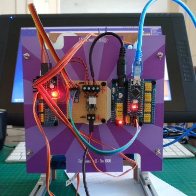
[SephenDeVos]’ beautiful barometer, dubbed Tempestas II,  demands nothing of the viewer, but will likely command attention anyway because it looks so cool. If the weather is anything but clear and sunny, the appropriate sun-obscuring weather actor, be it clouds, more clouds, rain, or lightning will swing into place, blocking out the blue sky in layers, just like real life.

There’s a total of five weather-serving servos, and they’re all controlled by an Arduino Nano through a 16-channel PWM driver. The Nano gets the news from a BMP280 barometric pressure/temperature sensor and drives the servos accordingly.

Nine layers of nicely-decorated Plexiglas® hide the clouds and things in the wings while it’s nice outside. We totally love the way this looks —  it’s even pretty on the back, where the sun don’t shine. This one is new and ongoing, so it seems likely that [Sephen] will post the code before the sun sets on this project. In the meantime, check out the demo after the break.

We don’t see too many barometers builds around here — maybe there’s too much pressure. This one tells you to lay off the coffee when the pressure’s too low.

Need a Thousand Extra PWM Pins?

If your Arduino runs out of I/O lines, you can always add one of the several I/O expander chips that takes a serial interface to set its several pins. Or perhaps you could buy something like an Arduino Mega, with its extra sockets to fulfil your needs. But what would you do if you really needed more pins, say a thousand of them? Perhaps [Brian Lough] has the answer. OK, full disclosure: If you really need a thousand, the video isn’t exactly for you, as he shows you how to add up to 992 PWM outputs. The chip he uses works with any microcontroller (the video shows an ESP8266), and we suppose you could use two daisy chains of them and break the 1,000 barrier handily.

We like how short the video is (just two minutes; see below) as it gets right to the point. The PCA9685 chip gives you 16 12-bit PWM channels via an I2C interface. You can daisy chain up to 62 of the boards to get the 992 outputs promised.

[Brian] uses a cheap $2 breakout board that lets you set a 6-bit address, has a nice power connector and makes it easy to use the little surface mount device. Each of the 16 outputs on the board can have an independent duty cycle, but they do share a single output frequency. That means if you want to use some channels for low-frequency devices like motors and some for high-frequency devices like LEDs, you might have to spring $4 for two boards.

Over on Hackaday.io, we’ve seen these devices driving 128 vibration motors. The PCA9685 made us think of the time we rolled our own serial to PWM devices using an FPGA.

Hack a Day 12 Apr 00:00

Flight Suit V3

The next version of the LED Flight Suit marches forward with WM, lots of headway on key components:
  • Three 16-channel, 12-bit pwm PCA9685 chips will operate MOSFET's to switch 48 LED strips.
  • Small sot23 smd MOSFETs (or these); the old ones (P16NF06's) were too overkill, too big. Overkill is still good but there's some math this time.
  • RC batteries for more power: peak 14.8V and 12A no problem, but will be <500mA most of the time.
  • Thinner, lighter LED strips with 120 LED's/m.
  • Arm-based remote control with a 1.3" OLED screen, dials/buttons/sliders/TBD.
    • The remote control will hopefully be a second Arduino-based system, a serial peripheral to the main suit system.
  • Multi-band audio analysis with MSGEQ7 or a separate Arduino FFT.
Most importantly WM is coding Arduino!  He already built a complete mode-switching, parameter-adjusting system with a figure diagram on-screen!  

We'll make the suits themselves-- the displays with LED strips-- when we have a working circuit and software: we don't know where everything's going yet.  So for a demo display I'm making a circuit board showing all 48 PCA9685 outputs on LED bars-- old school.  Here's the one I'm scrapping-- got too much rework:


and here's an MSGEQ7's output, from iphone audio, of seven values on a Sure Electronics 24x16 panel:


That display will also help when debugging and building the system.
Jeff's Arduino Blog 11 May 20:17

(F)Light Suit Progress: PWM!

I had a frustrating time trying to get a PCA9685 working-- it wouldn't even reply with its register byte values. I've interfaced with other I2C chips and didn't expect problems, but trouble was all I got.

Poking around the Arduino Forum trying to find any examples with a PCA9685, I found the thread on Elco Jacobs' new ShiftPWM library to drive the outputs of the ubiquitous 74HC595 shift register with 8-bit PWM precision. His demo video is on the right. The example sketch was so straightforward, I had two chips driving-- and dimming-- 16 red LED's in minutes.

Once I saw those red LED's cycling, I considered that part of the project done-- thank you, Elco!-- and started laying out a driver board with a 74HC595, eight outputs hooked up to MOSFETs and test LED's, and screw terminals so they can be daisy chained. With the DorkbotPDX order deadline this morning, I had to stay up late laying it out and getting a final Eagle brd file ready, and hopefully it will work; I wasn't that excited about asking for six copies of a 3.9"x2.1" V001 design and having no time for a second run if they don't work, but... hey, they'll work!

Here's the Eagle schematic: pdf, sch. And the board: pdf, brd.

LED (F)Light Suit: Ramping Up

I've been mesmerized by bouncing red LED's since the early '80s. LED's were mostly red, needle-style VU meters were on the outs, we hadn't yet graduated to green-yellow-red meters, and I grew a special place in my heart for those bouncing red lights. We also had KITT and the Cylons: bouncing red lights were and still are awesome ("rad" had not been invented yet).

I put together a black flight suit with red EL-wire segments for Burning Man in 2008 but did not have time to build the sequencer and control system I envisioned, so it was an on/off affair, or it pulsated to the music before the small batteries died.

Working on a suit for this year's burn, I've decided to return to the original concept-- red LED's-- and am working on the major areas now:
  • Suit electronics: Arduino core, I2C port expander w/PWM output using PCA9685 16-channel, 12-bit PWM I2C-bus LED controller driving power MOSFETs, one per segment. There are 17 segments in my design, so I'll use the port expander and then another spare pin to trigger the 17th channel.
  • Audio metering: I have a MaceTech Shifty VU shield working but I wonder about adjusting levels on the fly, and how to best get a mic input to it or something similar. There will be other modes for sequencing the lights, but bouncing VU meter is the primary mode I'm looking for.
  • Segment planning: location and length of each segment, power lead routing, attachment to suit. This is going well, with the first seven (of 22) segments cut and tested last night from my first 5M strip from DealExtreme; the suit will need 53' of light strip so I've ordered more.
  • Power: rechargable 12V power packs are easy to get; not sure how to recharge them on the Playa.
  • Remote control: would like to have a small, wireless remote to control modes and mode parameters.
  • The program: I have a list of modes I'd like to switch between, some of which have parameters I'll want to adjust on the fly. Ideally I'll be able to edit the program during the day if I come up with new ideas while I'm in BRC.